Downloads |
 Feedback Feedback
|
Table Of Contents
Replacing Memory Modules in Cisco AS5300 Universal Access Servers
Preventing Electrostatic Discharge Damage
Replacing Memory Modules in Cisco AS5300 Universal Access Servers
Product Numbers: MEM-8BF-53=
Product Numbers: MEM-8S-AS53= , MEM-16S-AS53=
Product Numbers: MEM-32M-AS53= , MEM-64M-AS53= , MEM-128MB-AS53=
Product Numbers: MEM-8F-AS53= , MEM-16F-AS53=
This document describes how to replace the boot ROMs, the shared and main memory DRAM SIMMs, and the Flash memory SIMMs, and includes the following sections:
Use this document with the Regulatory Compliance and Safety Information publication that shipped with the Cisco AS5300.
Safety Recommendations
Follow these guidelines to ensure general safety:
•
Keep the chassis area clear and dust-free before, during, and after installation.
•
•
•
•
•
Safety Warnings
Safety warnings appear throughout this publication in procedures that, if performed incorrectly, may harm you. A warning symbol precedes each safety warning.
Warning
This warning symbol means danger. You are in a situation that could cause bodily injury. Before you work on any equipment, be aware of the hazards involved with electrical circuitry and be familiar with standard practices for preventing accidents. To see translations of the warnings that appear in this publication, refer to the Regulatory Compliance and Safety Information document that accompanied this device.
Waarschuwing Dit waarschuwingssymbool betekent gevaar. U verkeert in een situatie die lichamelijk letsel kan veroorzaken. Voordat u aan enige apparatuur gaat werken, dient u zich bewust te zijn van de bij elektrische schakelingen betrokken risico's en dient u op de hoogte te zijn van standaard maatregelen om ongelukken te voorkomen. Voor vertalingen van de waarschuwingen die in deze publicatie verschijnen, kunt u het document Regulatory Compliance and Safety Information (Informatie over naleving van veiligheids- en andere voorschriften) raadplegen dat bij dit toestel is ingesloten.
Varoitus Tämä varoitusmerkki merkitsee vaaraa. Olet tilanteessa, joka voi johtaa ruumiinvammaan. Ennen kuin työskentelet minkään laitteiston parissa, ota selvää sähkökytkentöihin liittyvistä vaaroista ja tavanomaisista onnettomuuksien ehkäisykeinoista. Tässä julkaisussa esiintyvien varoitusten käännökset löydät laitteen mukana olevasta Regulatory Compliance and Safety Information -kirjasesta (määräysten noudattaminen ja tietoa turvallisuudesta).
Attention Ce symbole d'avertissement indique un danger. Vous vous trouvez dans une situation pouvant causer des blessures ou des dommages corporels. Avant de travailler sur un équipement, soyez conscient des dangers posés par les circuits électriques et familiarisez-vous avec les procédures couramment utilisées pour éviter les accidents. Pour prendre connaissance des traductions d'avertissements figurant dans cette publication, consultez le document Regulatory Compliance and Safety Information (Conformité aux règlements et consignes de sécurité) qui accompagne cet appareil.
Warnung Dieses Warnsymbol bedeutet Gefahr. Sie befinden sich in einer Situation, die zu einer Körperverletzung führen könnte. Bevor Sie mit der Arbeit an irgendeinem Gerät beginnen, seien Sie sich der mit elektrischen Stromkreisen verbundenen Gefahren und der Standardpraktiken zur Vermeidung von Unfällen bewußt. Übersetzungen der in dieser Veröffentlichung enthaltenen Warnhinweise finden Sie im Dokument Regulatory Compliance and Safety Information (Informationen zu behördlichen Vorschriften und Sicherheit), das zusammen mit diesem Gerät geliefert wurde.
Avvertenza Questo simbolo di avvertenza indica un pericolo. La situazione potrebbe causare infortuni alle persone. Prima di lavorare su qualsiasi apparecchiatura, occorre conoscere i pericoli relativi ai circuiti elettrici ed essere al corrente delle pratiche standard per la prevenzione di incidenti. La traduzione delle avvertenze riportate in questa pubblicazione si trova nel documento Regulatory Compliance and Safety Information (Conformità alle norme e informazioni sulla sicurezza) che accompagna questo dispositivo.
Advarsel Dette varselsymbolet betyr fare. Du befinner deg i en situasjon som kan føre til personskade. Før du utfører arbeid på utstyr, må du vare oppmerksom på de faremomentene som elektriske kretser innebærer, samt gjøre deg kjent med vanlig praksis når det gjelder å unngå ulykker. Hvis du vil se oversettelser av de advarslene som finnes i denne publikasjonen, kan du se i dokumentet Regulatory Compliance and Safety Information (Overholdelse av forskrifter og sikkerhetsinformasjon) som ble levert med denne enheten.
Aviso Este símbolo de aviso indica perigo. Encontra-se numa situação que lhe poderá causar danos físicos. Antes de começar a trabalhar com qualquer equipamento, familiarize-se com os perigos relacionados com circuitos eléctricos, e com quaisquer práticas comuns que possam prevenir possíveis acidentes. Para ver as traduções dos avisos que constam desta publicação, consulte o documento Regulatory Compliance and Safety Information (Informação de Segurança e Disposições Reguladoras) que acompanha este dispositivo.
¡Advertencia! Este símbolo de aviso significa peligro. Existe riesgo para su integridad física. Antes de manipular cualquier equipo, considerar los riesgos que entraña la corriente eléctrica y familiarizarse con los procedimientos estándar de prevención de accidentes. Para ver una traducción de las advertencias que aparecen en esta publicación, consultar el documento titulado Regulatory Compliance and Safety Information (Información sobre seguridad y conformidad con las disposiciones reglamentarias) que se acompaña con este dispositivo.
Varning! Denna varningssymbol signalerar fara. Du befinner dig i en situation som kan leda till personskada. Innan du utför arbete på någon utrustning måste du vara medveten om farorna med elkretsar och känna till vanligt förfarande för att förebygga skador. Se förklaringar av de varningar som förkommer i denna publikation i dokumentet Regulatory Compliance and Safety Information (Efterrättelse av föreskrifter och säkerhetsinformation), vilket medföljer denna anordning.
Safety with Electricity
Warning
Read the installation instructions before you connect the system to its power source.
Warning
Ultimate disposal of this product should be handled according to all national laws and regulations.
Warning
Only trained and qualified personnel should be allowed to install or replace this equipment.
Warning
Before working on a chassis or working near power supplies, unplug the power cord on AC units; disconnect the power at the circuit breaker on DC units.
Warning
Before performing any of the following procedures, ensure that power is removed from the DC circuit. To ensure that all power is OFF, locate the circuit breaker on the panel board that services the DC circuit, switch the circuit breaker to the OFF position, and tape the switch handle of the circuit breaker in the OFF position.
Warning
Before working on equipment that is connected to power lines, remove jewelry (including rings, necklaces, and watches). Metal objects will heat up when connected to power and ground and can cause serious burns or weld the metal object to the terminals.
Follow these guidelines when working on equipment powered by electricity:
•
•
•
•
•
•
•
•
•
•
•
•
Preventing Electrostatic Discharge Damage
Electrostatic discharge (ESD) can damage equipment and impair electrical circuitry. It occurs when electronic printed circuit cards are improperly handled and can result in complete or intermittent failures. Always follow ESD prevention procedures when removing and replacing cards. Ensure that the chassis is electrically connected to earth ground. Wear an ESD-preventive wrist strap, ensuring that it makes good skin contact. Connect the clip to an unpainted surface of the chassis frame to safely channel unwanted ESD voltages to ground. To properly guard against ESD damage and shocks, the wrist strap and cord must operate effectively. If no wrist strap is available, ground yourself by touching the metal part of the chassis.
CautionFor safety, periodically check the resistance value of the antistatic strap, which should be between 1 and 10 megohms (Mohm).
Cisco AS5300 Memory Systems
The Cisco AS5300 access server contains the following memory systems:
•
Main memory consists of dynamic random-access memory (DRAM) SIMMs. It is reserved for the CPU to execute Cisco IOS software and to hold the running configuration and routing tables.
•
Shared memory also consists of DRAM SIMMs, and buffers data transmitted or received by the server's network interfaces.
•
Flash memory stores the Cisco IOS software image and the boot helper, a subset of Cisco IOS software that allows the server to boot when Flash memory does not contain a valid Cisco IOS image.
Because Flash memory holds the Cisco IOS image, replacing or upgrading it causes the image to be lost. To restore it, you need a Trivial File Transfer Protocol (TFTP) file server that holds the desired image. You can then download the Cisco IOS files into the upgraded Flash memory using TFTP. Consult your network administrator about the availability of TFTP file servers and Cisco IOS software on your network. Refer to the Cisco IOS configuration guides and command references for TFTP procedures.
Note
•
•
Required Tools and Equipment
This kit includes one of the following items:
•
•
•
To remove or install the boot ROM or the SIMMs, you will also need the following tools and equipment (which are not included):
•
•
•
•
•
•
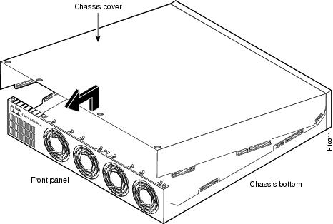
Removing the Chassis Cover
This section describes how gain access to the internal components by removing the chassis cover.
Warning
Do not touch the power supply when the power cord is connected. For systems with a power switch, line voltages are present within the power supply even when the power switch is off and the power cord is connected. For systems without a power switch, line voltages are present within the power supply when the power cord is connected.
Warning
Before working on a chassis or working near power supplies, unplug the power cord on AC units; disconnect the power at the circuit breaker on DC units.
Warning
Before opening the chassis, disconnect the telephone-network cables to avoid contact with telephone-network voltages.
Warning
Do not work on the system or connect or disconnect cables during periods of lightning activity.
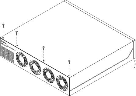
To remove the chassis cover:
Step 1
Step 2
Step 3
Step 4
Step 5
Place the chassis cover in a safe place where it will not be damaged.
Figure 1 Removing the Chassis Cover Screws
Figure 2 Removing the Chassis Cover
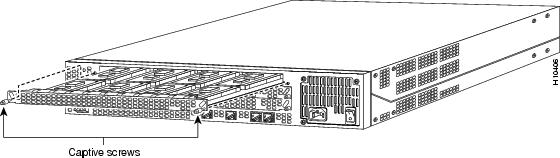
Removing Feature Cards
This section describes how to remove features cards. You must remove the feature cards to access the packet (shared) memory SIMM, one of the two main memory DRAM SIMMs, and the boot ROM. It is not necessary to remove the feature cards to access the Flash memory SIMMs.
Warning

To remove feature cards, refer to and take these steps:
Step 1 ![]() Turn the power switch on the access server OFF and disconnect site power.
Turn the power switch on the access server OFF and disconnect site power.
Step 2 ![]() Attach an ESD-preventive wrist strap.
Attach an ESD-preventive wrist strap.
Step 3 ![]() Remove all interface cables from the rear panel of the access server.
Remove all interface cables from the rear panel of the access server.
Step 4 ![]() Loosen the two captive screws that secure the feature card to the chassis until each screw is free of the chassis.
Loosen the two captive screws that secure the feature card to the chassis until each screw is free of the chassis.
Figure 3 Feature Card Removal (Carrier Card Shown)
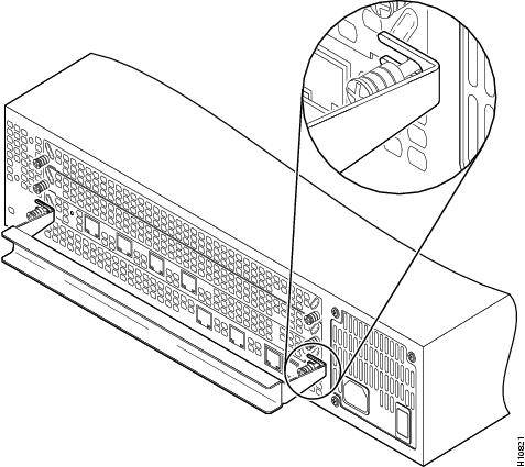
Step 5 ![]() Insert the feature card removal tool so that the slots in each arm of the tool are behind the shoulder of each captive screw, as shown in , and carefully pull the removal tool toward you until the feature card slides free of the chassis.
Insert the feature card removal tool so that the slots in each arm of the tool are behind the shoulder of each captive screw, as shown in , and carefully pull the removal tool toward you until the feature card slides free of the chassis.
Figure 4 Using the Feature Card Removal Tool
Step 6 ![]() Set the removed feature card aside on an ESD-preventive mat.
Set the removed feature card aside on an ESD-preventive mat.
Replacing the Boot ROM
To upgrade the boot ROM software to a new software image, you must replace the existing boot ROM.

Warning ![]()
Warning ![]()
To replace the boot ROM:
Step 1 ![]() Turn the power switch on the access server OFF and disconnect site power.
Turn the power switch on the access server OFF and disconnect site power.
Step 2 ![]() Attach an ESD-preventive wrist strap.
Attach an ESD-preventive wrist strap.
Step 3 ![]() Remove the chassis cover. (See the instructions in "Removing the Chassis Cover" in this document.)
Remove the chassis cover. (See the instructions in "Removing the Chassis Cover" in this document.)
Step 4 ![]() Remove all feature cards to access the system card. (See the instructions in "Removing Feature Cards" in this document.)
Remove all feature cards to access the system card. (See the instructions in "Removing Feature Cards" in this document.)
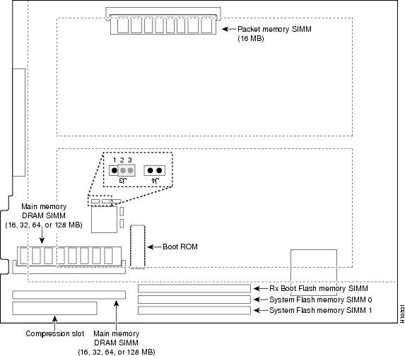
Step 5 ![]() Locate the boot ROM on the system card using .
Locate the boot ROM on the system card using .
Figure 5 System Card Layout
Step 6 ![]() Gently extract the old boot ROM with a ROM extraction tool or a small flat-blade screwdriver, and set the old boot ROM on a nonconductive surface.
Gently extract the old boot ROM with a ROM extraction tool or a small flat-blade screwdriver, and set the old boot ROM on a nonconductive surface.
Step 7 ![]() Insert the new boot ROM into the socket. Be careful not to bend or crush any of the bottom pins. If necessary, use needlenose pliers to straighten out any bent pins.
Insert the new boot ROM into the socket. Be careful not to bend or crush any of the bottom pins. If necessary, use needlenose pliers to straighten out any bent pins.
Step 8 ![]() Replace any feature cards removed. (See the instructions in "Replacing Feature Cards" in this document.)
Replace any feature cards removed. (See the instructions in "Replacing Feature Cards" in this document.)
Step 9 ![]() Replace the access server chassis cover. (See the instructions in "Replacing the Chassis Cover" in this document.)
Replace the access server chassis cover. (See the instructions in "Replacing the Chassis Cover" in this document.)
Step 10 ![]() Power ON the access server. If error messages relating to memory are displayed, remove the new boot ROM and reinstall it, taking care to seat the ROM firmly in its socket.
Power ON the access server. If error messages relating to memory are displayed, remove the new boot ROM and reinstall it, taking care to seat the ROM firmly in its socket.
Replacing DRAM SIMMs
This section describes how to replace the DRAM SIMMs on the system card. You might need to replace the DRAM SIMMs for the following reasons:
•![]() You have upgraded to a new Cisco IOS feature set or release that requires more memory.
You have upgraded to a new Cisco IOS feature set or release that requires more memory.
•![]() You are using very large routing tables or many protocols (for example, when the access server is set up as a connection device between large external networks and your internal network).
You are using very large routing tables or many protocols (for example, when the access server is set up as a connection device between large external networks and your internal network).
•![]() You are replacing a faulty SIMM.
You are replacing a faulty SIMM.
The system card contains three sockets for DRAM SIMMs (see ):
•![]() Two sockets hold main memory DRAM SIMMs. Main memory is used by the CPU to store the operating configuration, routing tables, caches, and queues. The SIMMs can be 16, 32, or 64 MB, and the capacity of the SIMMs in both sockets must match. Therefore, the total main memory is 32, 64, or 128 MB.
Two sockets hold main memory DRAM SIMMs. Main memory is used by the CPU to store the operating configuration, routing tables, caches, and queues. The SIMMs can be 16, 32, or 64 MB, and the capacity of the SIMMs in both sockets must match. Therefore, the total main memory is 32, 64, or 128 MB.
•![]() One socket holds a shared (packet) memory DRAM SIMM. Packet memory is used to store incoming and outgoing packets. This SIMM can be 16 MB.
One socket holds a shared (packet) memory DRAM SIMM. Packet memory is used to store incoming and outgoing packets. This SIMM can be 16 MB.
Warning ![]()
Warning ![]()
To replace the DRAM SIMMs:
Step 1 ![]() Turn the power switch on the access server OFF and disconnect site power.
Turn the power switch on the access server OFF and disconnect site power.
Step 2 ![]() Attach an ESD-preventive wrist strap.
Attach an ESD-preventive wrist strap.
Step 3 ![]() Remove the chassis cover. (See the instructions in the section "Removing the Chassis Cover" earlier in this document.)
Remove the chassis cover. (See the instructions in the section "Removing the Chassis Cover" earlier in this document.)
Step 4 ![]() Remove all feature cards to access the system card. (See the instructions in "Removing Feature Cards" in this document.)
Remove all feature cards to access the system card. (See the instructions in "Removing Feature Cards" in this document.)
Step 5 ![]() Use Figure 5 to locate the SIMM you are replacing.
Use Figure 5 to locate the SIMM you are replacing.
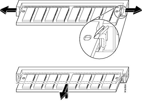
Step 6 ![]() Pull the socket latches away from the SIMM, and then pull the SIMM out of the socket, as shown in Figure 6. The latches hold the SIMM tightly, so be careful not to break the latches.
Pull the socket latches away from the SIMM, and then pull the SIMM out of the socket, as shown in Figure 6. The latches hold the SIMM tightly, so be careful not to break the latches.
Figure 6 Removing and Replacing the DRAM SIMM
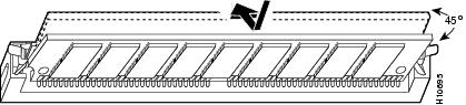
Step 7 ![]() Position the new SIMM so that the polarization notch is located at the right end of the SIMM socket.
Position the new SIMM so that the polarization notch is located at the right end of the SIMM socket.
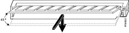
Step 8 ![]() Insert the new DRAM SIMM by sliding the end with the metal fingers into the SIMM socket at approximately a 45-degree angle to the system card, as shown in .
Insert the new DRAM SIMM by sliding the end with the metal fingers into the SIMM socket at approximately a 45-degree angle to the system card, as shown in .
Figure 7 Inserting the New DRAM SIMM in the Socket
Step 9 ![]() Gently rotate the SIMM until the latches snap into place, Do not use excessive force because the socket might break.
Gently rotate the SIMM until the latches snap into place, Do not use excessive force because the socket might break.

Note ![]() If upgrading to 128 MB (MEM-128M-AS53=), move jumper J3 from position 2-3 to position 1-2. shows jumper J3 in default position 2-3.
If upgrading to 128 MB (MEM-128M-AS53=), move jumper J3 from position 2-3 to position 1-2. shows jumper J3 in default position 2-3.
Step 10 ![]() Replace the feature cards. (See the instructions in "Replacing Feature Cards" in this document.)
Replace the feature cards. (See the instructions in "Replacing Feature Cards" in this document.)
Step 11 ![]() Replace the access server chassis cover. (See the instructions in "Replacing the Chassis Cover" in this document.)
Replace the access server chassis cover. (See the instructions in "Replacing the Chassis Cover" in this document.)
Step 12 ![]() Power ON the access server. If error messages relating to memory are displayed, remove the DRAM SIMM and reinstall it, taking care to seat the SIMM firmly in its socket.
Power ON the access server. If error messages relating to memory are displayed, remove the DRAM SIMM and reinstall it, taking care to seat the SIMM firmly in its socket.
Replacing Flash Memory SIMMs
The system card contains three sockets for Flash memory SIMMs (see ):
•![]() Two sockets hold SIMMs containing the system software (Cisco IOS) image. Both of these SIMMs, labeled SIMM0 and SIMM1, must be installed. The SIMMs can be 8 or 16 MB, and the capacity of both SIMMs must match.
Two sockets hold SIMMs containing the system software (Cisco IOS) image. Both of these SIMMs, labeled SIMM0 and SIMM1, must be installed. The SIMMs can be 8 or 16 MB, and the capacity of both SIMMs must match.
•![]() One socket holds a SIMM for the boot helper image (rxboot) software. This SIMM, labeled BOOT, must also be installed. The SIMM can be 8 or 16 MB.
One socket holds a SIMM for the boot helper image (rxboot) software. This SIMM, labeled BOOT, must also be installed. The SIMM can be 8 or 16 MB.
Because Flash memory holds the Cisco IOS image, replacing or upgrading it causes the image to be lost. To restore it, you need a Trivial File Transfer Protocol (TFTP) file server that holds the desired image. You can then download the Cisco IOS files into the upgraded Flash memory using TFTP. Consult your network administrator about the availability of TFTP file servers and Cisco IOS software on your network. Refer to the Cisco IOS configuration guides and command references for TFTP procedures.
Note ![]() One upgraded server can function as a TFTP server to upgrade other servers.
One upgraded server can function as a TFTP server to upgrade other servers.
Flash memory SIMMs must be purchased from Cisco Systems, Inc. For ordering information, refer to the Information Packet that accompanied your access server.
Warning ![]()
Warning ![]()
To replace the Flash Memory SIMMs:
Step 1 ![]() Turn the power switch on the access server OFF and disconnect site power.
Turn the power switch on the access server OFF and disconnect site power.
Step 2 ![]() Attach an ESD-preventive wrist strap.
Attach an ESD-preventive wrist strap.
Step 3 ![]() Remove the chassis cover. (See the procedure in "Removing the Chassis Cover" in this document.)
Remove the chassis cover. (See the procedure in "Removing the Chassis Cover" in this document.)
Step 4 ![]() Place the chassis so that the system card is oriented as shown in Figure 5, with the Flash memory SIMMs toward you. The system-code SIMM sockets are labeled SIMM0 and SIMM1; the rxboot SIMM socket is labeled SIMM.
Place the chassis so that the system card is oriented as shown in Figure 5, with the Flash memory SIMMs toward you. The system-code SIMM sockets are labeled SIMM0 and SIMM1; the rxboot SIMM socket is labeled SIMM.
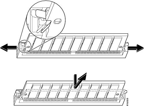
Step 5 ![]() Remove the existing Flash memory SIMM by pulling outward on the socket latches and then lifting the SIMM out of the socket (see ).
Remove the existing Flash memory SIMM by pulling outward on the socket latches and then lifting the SIMM out of the socket (see ).
Figure 8 Removing the Flash Memory SIMM
Step 6 ![]() Repeat these steps for all the Flash memory SIMMs that you need to replace.
Repeat these steps for all the Flash memory SIMMs that you need to replace.
Step 7 ![]() Insert the new SIMM by sliding the end with the metal fingers into the appropriate SIMM socket at approximately a 45-degree angle to the system card as shown in .
Insert the new SIMM by sliding the end with the metal fingers into the appropriate SIMM socket at approximately a 45-degree angle to the system card as shown in .
Figure 9 Inserting the Flash Memory SIMM
Step 8 ![]() Gently rotate the SIMM until the latch on either side snaps into place. Do not use excessive force because the connector might break. When inserting the new SIMM, make sure that the polarization notch is located at the right end of the SIMM socket.
Gently rotate the SIMM until the latch on either side snaps into place. Do not use excessive force because the connector might break. When inserting the new SIMM, make sure that the polarization notch is located at the right end of the SIMM socket.
Step 9 ![]() Replace any feature cards removed. (See the instructions in "Replacing Feature Cards" in this document.)
Replace any feature cards removed. (See the instructions in "Replacing Feature Cards" in this document.)
Step 10 ![]() Replace the access server chassis cover. (See the instructions in "Replacing the Chassis Cover" in this document.)
Replace the access server chassis cover. (See the instructions in "Replacing the Chassis Cover" in this document.)
Step 11 ![]() Connect the access server to a console terminal.
Connect the access server to a console terminal.
Step 12 ![]() Power ON the access server. If any memory-related error messages appear, remove the Flash memory SIMM and reinstall it, taking care to seat the SIMM firmly in the socket.
Power ON the access server. If any memory-related error messages appear, remove the Flash memory SIMM and reinstall it, taking care to seat the SIMM firmly in the socket.
Replacing Feature Cards
This section describes how to replace the features cards, which were removed to access the system board.
Warning ![]()
To replace feature cards, refer to and take these steps:
Step 1 ![]() Remove the feature card from the ESD-preventive mat.
Remove the feature card from the ESD-preventive mat.
Step 2 ![]() Slide the card into the slot until it touches the backplane connector.
Slide the card into the slot until it touches the backplane connector.
Figure 10 Feature Card Replacement (Carrier Card Shown)
Step 3 ![]() Align the captive screws with their holes, and then seat the card completely.
Align the captive screws with their holes, and then seat the card completely.
Step 4 ![]() Tighten the two captive screws to secure the card to the chassis.
Tighten the two captive screws to secure the card to the chassis.
Step 5 ![]() If the access server is configured with fewer than three cards, make sure that a blank slot cover is installed over each open slot to ensure proper airflow inside the chassis.
If the access server is configured with fewer than three cards, make sure that a blank slot cover is installed over each open slot to ensure proper airflow inside the chassis.
Step 6 ![]() Replace the access server chassis cover. (See the instructions in "Replacing the Chassis Cover" in this document.)
Replace the access server chassis cover. (See the instructions in "Replacing the Chassis Cover" in this document.)
Replacing the Chassis Cover
To replace the chassis cover, refer to and take these steps:
Step 1 ![]() Place the chassis bottom so that the front panel is facing you.
Place the chassis bottom so that the front panel is facing you.
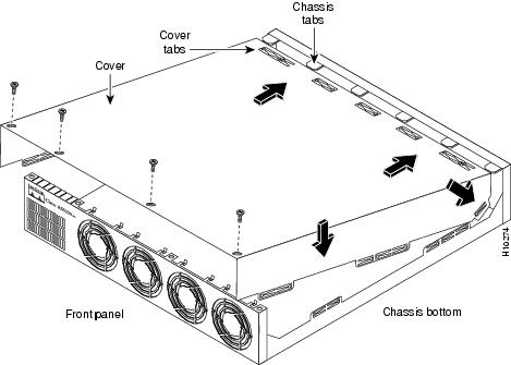
Step 2 ![]() Hold the chassis cover over the chassis bottom, and align each of the cover tabs with the chassis tabs at the top rear of the chassis, as shown in Figure 11.
Hold the chassis cover over the chassis bottom, and align each of the cover tabs with the chassis tabs at the top rear of the chassis, as shown in Figure 11.
Figure 11 Replacing the Chassis Cover
Step 3 ![]() Lower the front of the chassis cover to close the chassis.
Lower the front of the chassis cover to close the chassis.
When the chassis cover is closed, ensure the following:
•![]() The chassis cover tabs fit under the edge of the rear panel so that they are not exposed.
The chassis cover tabs fit under the edge of the rear panel so that they are not exposed.
•![]() The chassis tabs fit under the chassis cover so that they are not exposed.
The chassis tabs fit under the chassis cover so that they are not exposed.
•![]() The chassis cover side tabs on both sides fit inside the chassis side panels so that they are not exposed.
The chassis cover side tabs on both sides fit inside the chassis side panels so that they are not exposed.
When the chassis cover is properly assembled, no tabs should be visible.
Step 4 ![]() Secure the chassis cover with four screws.
Secure the chassis cover with four screws.
Step 5 ![]() Reinstall the chassis on a rack, desktop, or table.
Reinstall the chassis on a rack, desktop, or table.
Step 6 ![]() Reinstall all interface cables and reconnect the AC power cord or rewire the DC power supply.
Reinstall all interface cables and reconnect the AC power cord or rewire the DC power supply.
Warning ![]()
After wiring the DC power supply, remove the tape from the circuit breaker switch handle and reinstate power by moving the handle of the circuit breaker to the ON position.
Step 7 ![]() Power ON the access server.
Power ON the access server.
The internal power supply fan and the exhaust fans should power on.
Cisco Connection Online
Cisco Connection Online (CCO) is Cisco Systems' primary, real-time support channel. Maintenance customers and partners can self-register on CCO to obtain additional information and services.
Available 24 hours a day, 7 days a week, CCO provides a wealth of standard and value-added services to Cisco's customers and business partners. CCO services include product information, product documentation, software updates, release notes, technical tips, the Bug Navigator, configuration notes, brochures, descriptions of service offerings, and download access to public and authorized files.
CCO serves a wide variety of users through two interfaces that are updated and enhanced simultaneously: a character-based version and a multimedia version that resides on the World Wide Web (WWW). The character-based CCO supports Zmodem, Kermit, Xmodem, FTP, and Internet e-mail, and it is excellent for quick access to information over lower bandwidths. The WWW version of CCO provides richly formatted documents with photographs, figures, graphics, and video, as well as hyperlinks to related information.
You can access CCO in the following ways:
•![]() WWW: http://www.cisco.com
WWW: http://www.cisco.com
•![]() WWW: http://www-europe.cisco.com
WWW: http://www-europe.cisco.com
•![]() WWW: http://www-china.cisco.com
WWW: http://www-china.cisco.com
•![]() Telnet: cco.cisco.com
Telnet: cco.cisco.com
•![]() Modem: From North America, 408 526-8070; from Europe, 33 1 64 46 40 82. Use the following terminal settings: VT100 emulation; databits: 8; parity: none; stop bits: 1; and connection rates up to 28.8 kbps.
Modem: From North America, 408 526-8070; from Europe, 33 1 64 46 40 82. Use the following terminal settings: VT100 emulation; databits: 8; parity: none; stop bits: 1; and connection rates up to 28.8 kbps.
For a copy of CCO's Frequently Asked Questions (FAQ), contact cco-help@cisco.com. For additional information, contact cco-team@cisco.com.
Note ![]() If you are a network administrator and need personal technical assistance with a Cisco product that is under warranty or covered by a maintenance contract, contact Cisco's Technical Assistance Center (TAC) at 800 553-2447, 408 526-7209, or tac@cisco.com. To obtain general information about Cisco Systems, Cisco products, or upgrades, contact 800 553-6387, 408 526-7208, or cs-rep@cisco.com.
If you are a network administrator and need personal technical assistance with a Cisco product that is under warranty or covered by a maintenance contract, contact Cisco's Technical Assistance Center (TAC) at 800 553-2447, 408 526-7209, or tac@cisco.com. To obtain general information about Cisco Systems, Cisco products, or upgrades, contact 800 553-6387, 408 526-7208, or cs-rep@cisco.com.
78-4518-02 Rev. -C0