Feedback
Table Of Contents
Configuring the Role in the Radio Network
Configuring Radio Transmit Power
Limiting the Power Level for Associated Client Devices
Configuring Radio Channel Settings
Enabling and Disabling World Mode
Disabling and Enabling Short Radio Preambles
Configuring Transmit and Receive Antennas
Disabling and Enabling Aironet Extensions
Configuring the Ethernet Encapsulation Transformation Method
Enabling and Disabling Public Secure Packet Forwarding
Configuring the Beacon Period and the DTIM
Configure RTS Threshold and Retries
Configuring the Maximum Data Retries
Configuring the Fragmentation Threshold
Enabling Short Slot Time for 802.11g Radios
Performing a Carrier Busy Test
Configuring VoIP Packet Handling
Configuring Radio Settings
This module describes how to configure radio settings for the wireless device in the following sections:
•
Configuring the Role in the Radio Network
•
•
•
•
•
•
•
•
•
•
•
•
•
•
•
Enabling the Radio Interface
The wireless device radios are disabled by default.
Note
To enable the access point radio, follow these steps, beginning in privileged EXEC mode:
SUMMARY STEPS
1.
2.
3.
4.
5.
6.
7.
DETAILED STEPS
Use the shutdown command to disable the radio port.
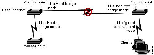
Configuring the Role in the Radio Network
The radio performs the following roles in the wireless network:
•
•
•
•
•
•
You can also configure a fallback role for root access points. The wireless device automatically assumes the fallback role when its Ethernet port is disabled or disconnected from the wired LAN. The default fallback role for Cisco ISR wireless devices is as follows:
Shutdown—the wireless device shuts down its radio and disassociates all client devices.
To set the wireless device's radio network role and fallback role, follow these steps, beginning in privileged EXEC mode:
SUMMARY STEPS
1.
2.
3.
mode <client | infrastructure>| universal <Ethernet client MAC address>}4.
5.
DETAILED STEPS
Note
Radio Tracking
You can configure the access point to track or monitor the status of one of its radios. If the tracked radio goes down or is disabled, the access point shuts down the other radio. If the tracked radio comes up, the access point enables the other radio.
To track radio 0, enter the following command:
# station-role root access-point fallback track d0 shutdownFast Ethernet Tracking
You can configure the access point for fallback when its Ethernet port is disabled or disconnected from the wired LAN. For guidance on configuring the access point for Fast Ethernet tracking, see the "Configuring the Role in the Radio Network" section.
Note
To configure the access point for Fast Ethernet tracking, enter the following command:
# station-role root access-point fallback track fa 0MAC-Address Tracking
You can configure the radio whose role is root access point to come up or go down by tracking a client access point, using its MAC address, on another radio. If the client disassociates from the access point, the root access point radio goes down. If the client reassociates to the access point, the root access point radio comes back up.
MAC-address tracking is most useful when the client is a non-root bridge access point connected to an upstream wired network.
For example, to track a client whose MAC address is 12:12:12:12:12:12, enter the following command:
# station-role root access-point fallback track mac-address 12:12:12:12:12:12 shutdownConfiguring Radio Data Rates
You use the data rate settings to choose the data rates that the wireless device uses for data transmission. The rates are expressed in megabits per second (Mb/s). The wireless device always attempts to transmit at the highest data rate set to basic, also known as required on the browser-based interface. If there are obstacles or interference, the wireless device steps down to the highest rate that allows data transmission. You can set each data rate to one of three states:
•
•
•
Note
You can use the data rate settings to set an access point to serve client devices operating at specific data rates. For example, to set the 2.4-GHz radio for 11 Mb/s service only, set the 11-Mb/s rate to basic, and set the other data rates to disabled. To set the wireless device to serve only client devices operating at 1 and 2 Mb/s, set 1 and 2 to basic, and set the rest of the data rates to disabled. To set the 2.4-GHz, 802.11g radio to serve only 802.11g client devices, set any orthogonal frequency division multiplexing (OFDM) data rate (6, 9, 12, 18, 24, 36, 48, 54) to basic. To set the 5-GHz radio for 54-Mb/s service only, set the 54-Mb/s rate to basic, and set the other data rates to disabled.
You can configure the wireless device to set the data rates automatically to optimize either the range or the throughput. When you enter range for the data rate setting, the wireless device sets the 1-Mb/s rate to basic and sets the other rates to enabled. The range setting allows the access point to extend the coverage area by compromising on the data rate. Therefore, if you have a client that cannot connect to the access point although other clients can, the client might not be within the coverage area of the access point. In such a case, using the range option will help extend the coverage area, and the client may be able to connect to the access point.
Typically, the trade-off is between throughput and range. When the signal degrades (possibly due to distance from the access point), the rates renegotiate in order to maintain the link (but at a lower data rate). A link that is configured for a higher throughput simply drops when the signal degrades enough that it no longer sustains a configured high data rate, or the link roams to another access point with sufficient coverage, if one is available. The balance between the two (throughput vs. range) is a design decision that must be made based on resources available to the wireless project, the type of traffic the users will be passing, the service level desired, and as always, the quality of the RF environment. When you enter throughput for the data rate setting, the wireless device sets all four data rates to basic.
Note
To configure the radio data rates, follow these steps, beginning in privileged EXEC mode:
SUMMARY STEPS
1.
2.
3.
4.
5.
DETAILED STEPS
Use the no form of the speed command to remove one or more data rates from the configuration. This example shows how to remove data rates basic-2.0 and basic-5.5 from the configuration:
ap1200# configure terminalap1200(config)# interface dot11radio 0ap1200(config-if)# no speed basic-2.0 basic-5.5ap1200(config-if)# endConfiguring MCS Rates
Modulation coding scheme (MCS) is a specification of PHY parameters consisting of modulation order (binary phase shift keying [BPSK], quaternary phase shift keying [QPSK], 16-quadrature amplitude modulation [16-QAM], 64-QAM) and forward error correction (FEC) code rate (1/2, 2/3, 3/4, 5/6). MCS is used in the wireless device 802.11n radios, which define 32 symmetrical settings (8 per spatial stream):
•
•
•
•
The wireless device supports MCS 0-15. High-throughput clients support at least MCS 0-7.
MCS is an important setting because it provides for potentially greater throughput. High-throughput data rates are a function of MCS, bandwidth, and guard interval. The 802.11a, b, and g radios use 20-MHz channel widths. Table 5-1 shows potential data rated based on MCS, guard interval, and channel width.
MCS rates are configured using the speed command. The following example shows a speed setting for an 802.11g/n 2.4-GHz radio:
interface Dot11Radio0no ip addressno ip route-cache!ssid 800test!speed basic-1.0 2.0 5.5 11.0 6.0 9.0 12.0 18.0 24.0 36.0 48.0 54.0 m0. m1. m2. m3. m4. m8. m9. m10. m11. m12. m13. m14. m15.Configuring Radio Transmit Power
Radio transmit power is based on the type of radio or radios installed in your access point and the regulatory domain in which it operates.
To set the transmit power on access point radios, follow these steps, beginning in privileged EXEC mode:
SUMMARY STEPS
1.
2.
3.
4.
5.
DETAILED STEPS
Use the no form of the power local command to return the power setting to maximum, the default setting.
Limiting the Power Level for Associated Client Devices
You can also limit the power level on client devices that associate to the wireless device. When a client device associates to the wireless device, the wireless device sends the maximum power level setting to the client.
Note
To specify a maximum allowed power setting on all client devices that associate to the wireless device, follow these steps, beginning in privileged EXEC mode:
SUMMARY STEPS
1.
2.
3.
4.
5.
DETAILED STEPS
Use the no form of the power client command to disable the maximum power level for associated clients.
Note
Configuring Radio Channel Settings
The default channel setting for the wireless device radios is least congested. At startup, the wireless device scans for and selects the least-congested channel. For the most consistent performance after a site survey, however, we recommend that you assign a static channel setting for each access point. The channel settings on the wireless device correspond to the frequencies available in your regulatory domain. See the access point hardware installation guide for the frequencies allowed in your domain.
Each 2.4-GHz channel covers 22 MHz. Because the bands for channels 1, 6, and 11 do not overlap, you can set up multiple access points in the same vicinity without causing interference. The 802.11b and 802.11g 2.4-GHz radios use the same channels and frequencies.
The 5-GHz radio operates on 8 channels from 5180 to 5320 MHz, up to 27 channels from 5170 to 5850 MHz depending on regulatory domain. Each channel covers 20 MHz, and the bands for the channels overlap slightly. For best performance, use channels that are not adjacent (use channels 44 and 46, for example) for radios that are close to each other.
Note
802.11n Channel Widths
The 802.11n standard allows both 20-MHz and 40-Mhz channel widths consisting of two contiguous non-overlapping channels (for example, 2.4-GHz channels 1 and 6).
One of the 20-MHz channels is called the control channel. Legacy clients and 20-MHz high-throughput clients use the control channel. Only beacons can be sent on this channel. The other 20-MHz channel is called the extension channel. The 40-MHz stations may use this channel and the control channel simultaneously.
A 40-MHz channel is specified as a channel and extension, such as 1,1. In this example, the control channel is channel 1 and the extension channel is above it.
To set the wireless device channel width, follow these steps, beginning in privileged EXEC mode:
SUMMARY STEPS
1.
2.
3.
4.
5.
DETAILED STEPS
Step 1
configure terminal
Enters global configuration mode.
Step 2
interface dot11radio {0 }
Enters interface configuration mode for the radio interface.
•
Step 3
channel
{frequency | least-congested | width [20 | 40-above | 40-below] | dfs}Sets the default channel for the wireless device radio.To search for the least-congested channel on startup, enter least-congested.
•
–
–
–
Note
Step 4
end
Returns to privileged EXEC mode.
Step 5
copy running-config startup-config
(Optional) Saves your entries in the configuration file.
Enabling and Disabling World Mode
You can configure the wireless device to support 802.11d world mode, Cisco legacy world mode, or world mode roaming. When you enable world mode, the wireless device adds channel carrier set information to its beacon. Client devices with world mode enabled receive the carrier set information and adjust their settings automatically. For example, a client device used primarily in Japan could rely on world mode to adjust its channel and power settings automatically when it travels to Italy and joins a network there. Cisco client devices detect whether the wireless device is using 802.11d or Cisco legacy world mode and automatically use the world mode that matches the mode used by the wireless device.
You can also configure world mode to be always on. In this configuration, the access point essentially roams between countries and changes its settings as required.
World mode is disabled by default.
To enable world mode, follow these steps, beginning in privileged EXEC mode:
SUMMARY STEPS
1.
2.
3.
4.
5.
DETAILED STEPS
Use the no form of the world-mode command to disable world mode.
Disabling and Enabling Short Radio Preambles
The radio preamble (sometimes called a header) is a section of data at the head of a packet that contains information that the wireless device and client devices need when sending and receiving packets. You can set the radio preamble to long or short:
•
•
You cannot configure short or long radio preambles on the 5-GHz radio.
To disable short radio preambles, follow these steps, beginning in privileged EXEC mode:
SUMMARY STEPS
1.
2.
3.
4.
5.
DETAILED STEPS
Short preambles are enabled by default. Use the preamble-short command to enable short preambles if they are disabled.
Configuring Transmit and Receive Antennas
You can select the antenna that the wireless device uses to receive and transmit data. There are three options for both the receive antenna and the transmit antenna:
•
•
•
•
To select the antennas that the wireless device uses to receive and transmit data, follow these steps, beginning in privileged EXEC mode:
SUMMARY STEPS
1.
2.
3.
4.
5.
6.
DETAILED STEPS
Disabling and Enabling Aironet Extensions
By default, the wireless device uses Cisco Aironet 802.11 extensions to detect the capabilities of Cisco Aironet client devices and to support features that require specific interaction between the wireless device and associated client devices. Aironet extensions must be enabled to support these features:
•
•
•
•
•
Disabling Aironet extensions disables the features listed above, but it sometimes improves the ability of non-Cisco client devices to associate to the wireless device.
Aironet extensions are enabled by default. To disable Aironet extensions, follow these steps, beginning in privileged EXEC mode:
SUMMARY STEPS
1.
2.
3.
4.
5.
DETAILED STEPS
Use the dot11 extension aironet command to enable Aironet extensions if they are disabled.
Configuring the Ethernet Encapsulation Transformation Method
When the wireless device receives data packets that are not 802.3 packets, the wireless device must format the packets to 802.3 by using an encapsulation transformation method. These are the two transformation methods:
•
•
To configure the encapsulation transformation method, follow these steps, beginning in privileged EXEC mode:
SUMMARY STEPS
1.
2.
3.
4.
5.
DETAILED STEPS
Enabling and Disabling Public Secure Packet Forwarding
Public Secure Packet Forwarding (PSPF) prevents client devices that are associated to an access point from inadvertently sharing files or communicating with other client devices that are associated to the access point. PSPF provides Internet access to client devices without providing other capabilities of a LAN. This feature is useful for public wireless networks like those installed in airports or on college campuses.
Note
To enable and disable PSPF using CLI commands on the wireless device, you use bridge groups. For a detailed explanation on bridge groups and instructions for implementing them, see the Configuring Transparent Bridging chapter of Cisco IOS Bridging and IBM Networking Configuration Guide, Release 12.2 at the following link:
PSPF is disabled by default. To enable PSPF, follow these steps, beginning in privileged EXEC mode:
SUMMARY STEPS
1.
2.
3.
4.
5.
DETAILED STEPS
Use the no form of the bridge group command to disable PSPF.
Configuring Protected Ports
To prevent communication between client devices that are associated to different access points on your wireless LAN, you must set up protected ports on the switch to which the wireless devices are connected.
To define a port on your switch as a protected port, follow these steps, beginning in privileged EXEC mode:
SUMMARY STEPS
1.
2.
3.
4.
5.
6.
DETAILED STEPS
To disable protected port, use the no switchport protected command.
For detailed information on protected ports and port blocking, see the "Configuring Port-Based Traffic Control" chapter in Catalyst 3550 Multilayer Switch Software Configuration Guide, 12.1(12c)EA1 at the following URL:
Configuring the Beacon Period and the DTIM
The beacon period is the amount of time between access point beacons in kilomicroseconds (Kmicrosecs). One Kmicrosec equals 1,024 microseconds. The data beacon rate, always a multiple of the beacon period, determines how often the beacon contains a delivery traffic indication message (DTIM). The DTIM tells power-save client devices that a packet is waiting for them.
For example, if the beacon period is set at 100, its default setting, and if the data beacon rate is set at 2, its default setting, then the wireless device sends a beacon containing a DTIM every 200 Kmicrosecs.
The default beacon period is 100, and the default DTIM is 2. To configure the beacon period and the DTIM, follow these steps, beginning in privileged EXEC mode:
SUMMARY STEPS
1.
2.
3.
4.
5.
6.
DETAILED STEPS
Configure RTS Threshold and Retries
The request to send (RTS) threshold determines the packet size at which the wireless device issues an RTS before sending the packet. A low RTS threshold setting can be useful in areas where many client devices are associating with the wireless device or in areas where the clients are far apart and can detect only the wireless device and not detect each other. You can enter a setting ranging from 0 to 2347 bytes.
The maximum RTS retries is the maximum number of times the wireless device issues an RTS before stopping the attempt to send the packet over the radio. Enter a value from 1 to 128.
The default RTS threshold is 2347 for all access points and bridges, and the default maximum RTS retries setting is 32.
To configure the RTS threshold and maximum RTS retries, follow these steps, beginning in privileged EXEC mode:
SUMMARY STEPS
1.
2.
3.
4.
5.
6.
DETAILED STEPS
Use the no form of the rts command to reset the RTS settings to defaults.
Configuring the Maximum Data Retries
The maximum data retries setting determines the number of attempts that the wireless device makes to send a packet before it drops the packet. The default setting is 32.
To configure the maximum data retries, follow these steps, beginning in privileged EXEC mode:
SUMMARY STEPS
1.
2.
3.
4.
5.
DETAILED STEPS
Use the no form of the packet retries command to reset the setting to the default.
Configuring the Fragmentation Threshold
The fragmentation threshold determines the size at which packets are fragmented (sent as several pieces instead of as one block). Use a low setting in areas where communication is poor or where there is a great deal of radio interference. The default setting is 2346 bytes.
To configure the fragmentation threshold, follow these steps, beginning in privileged EXEC mode:
SUMMARY STEPS
1.
2.
3.
4.
5.
DETAILED STEPS
Use the no form of the fragment-threshold command to reset the setting to the default.
Enabling Short Slot Time for 802.11g Radios
You can increase throughput on the 802.11g 2.4-GHz radio by enabling short slot time. Reducing the slot time from the standard 20 microseconds to the 9-microsecond short slot time decreases the overall backoff, which increases throughput. Backoff, which is a multiple of the slot time, is the random length of time that a station waits before sending a packet on the LAN.
Many 802.11g radios support short slot time, but some do not. When you enable short slot time, the wireless device uses the short slot time only when all clients associated to the 802.11g 2.4-GHz radio support short slot time.
Short slot time is supported only on the 802.11g 2.4-GHz radio. Short slot time is disabled by default.
In radio interface mode, enter the short-slot-time command to enable short slot time:
ap(config-if)# short-slot-timeUse the no form of the short-slot-time command to disable short slot time.
Performing a Carrier Busy Test
You can perform a carrier busy test to check the radio activity on wireless channels. During the carrier busy test, the wireless device drops all associations with wireless networking devices for 4 seconds while it conducts the carrier test and then displays the test results.
In privileged EXEC mode, enter this command to perform a carrier busy test:
dot11 interface-number carrier busyFor interface-number, enter dot11radio 0 to run the test on the 2.4-GHz radio.
Use the show dot11 carrier busy command to redisplay the carrier busy test results.
Configuring VoIP Packet Handling
You can improve the quality of VoIP packet handling per radio on access points by enhancing 802.11 MAC behavior for lower latency for the class of service (CoS) 5 (Video) and CoS 6 (Voice) user priorities.
To configure VoIP packet handling on an access point, follow these steps:
Step 1
Step 2
Step 3
The Stream page appears.
Step 4
Step 5
The default value for maximum retries is 3 for the Low Latency setting (Figure 5-1). This value indicates how many times the access point will try to retrieve a lost packet before discarding it.
Figure 5-1 Packet Handling Configuration
Note
Step 6
You can also configure VoIP packet handling using the CLI. For a list of Cisco IOS commands for configuring VoIP packet handling using the CLI, consult Cisco IOS Command Reference for Cisco Aironet Access Points and Bridges.