Cisco 7200 VXR Routers Quick Start Guide
Available Languages
Table Of Contents
Cisco Product Security Overview
Reporting Security Problems in Cisco Products
Obtaining Additional Publications and Information
Site Preparation and Unpacking
Prepare for Workbench or Tabletop Installation
Prepare for Rack-Mount Installation
Install the CompactFlash Disk, GBICs, and SFPs on the NPE-G1 or NPE-G2
Brackets Front-Mounted—Chassis Protrudes from the Rack
Brackets Front-Mounted—Chassis Recessed in Rack
NPE-G1 and NPE-G2 Rear Cable-Management Brackets on a Front-Mounted Router
Brackets Rear-Mounted—Front Protrudes from the Rack
Brackets Rear-Mounted—Front Recessed in the Rack
NPE-G1 or NPE-G2 Rear Cable-Management Brackets on a Rear-Mounted Router
NPE-G1 or NPE-G2 Optical Cable-Management Bracket
Two-Post or Four-Post Rack Installation
Connect the Router to the Network
I/O Controller and NPE-G1 or NPE-G2 Console and Auxiliary Port Cable Connections
SFP and GBIC Interface Cables Installation
Attach the Multimode and Single-Mode Optical Fiber Cables
Attach the Mode-Conditioning Patch Cord
Port Adapter Cable Connections
Placing the Cables in the Cable-Management Brackets
Start and Configure the Router
Important NPE-G1 and NPE-G2 Information
Start the System and Perform a Basic Configuration
Perform a Basic Configuration Using the Setup Facility
Configuration Information for the NPE-G1 or NPE-G2
Configure an Auxiliary Port to Receive Console Port Messages for the NPE-G1 or NPE-G2
Configure the Native Gigabit Ethernet Interfaces on the NPE-G1 or NPE-G2
Change the Media Type of the Native Gigabit Ethernet SFP, GBIC, or RJ-45 Ports
Configure the Interface Transmission and Speed Modes for the NPE-G1 or NPE-G2
Reset the Interface on the NPE-G1 or NPE-G2
Clear Counters on the NPE-G1 or NPE-G2
Configure Fast Ethernet Interfaces
Configure Synchronous Serial Interfaces
Save the Running Configuration to NVRAM
Check the Running Configuration Settings
View Your System Configuration
Perform Complex Configurations
Replace or Recover a Lost Password
Replace the Network Processing Engine or Network Services Engine
Replace the PC Card, Flash Memory Card, Flash Disk, CompactFlash Disk, or USB Token
Replace the Gigabit Interface Converter
Installing a USB Flash Memory Module or eToken—NPE-G2
Replace a Port Adapter or Service Adapter
Replace the Port Adapter Jacket Card
Cisco Product Security Overview
Reporting Security Problems in Cisco Products
Obtaining Technical Assistance
Cisco Technical Support & Documentation Website
Definitions of Service Request Severity
Quick Start Guide
Cisco 7200 VXR Routers
1 Documentation and Resources
This section contains information to help you prepare for installing the Cisco 7200 VXR router. It contains a list of online documentation and resources.
Document Revision History
The document revision history is in Table 1.
Documentation Survey
Is Cisco documentation helpful? Click here or go to http://forums.cisco.com/eforum/servlet/viewsflash?cmd=showform&pollid=rtgdoc01!rtgdoc to give us your feedback.
Related Documentation
For detailed hardware installation instructions, refer to the online Cisco 7200 VXR Installation and Configuration Guide at http://www.cisco.com/en/US/docs/routers/7200/install_and_upgrade/7200vxr_install_config/72vxicg.html.
For other documentation, see the following online documentation roadmaps for a listing of all documents related to this product:
For other documentation, see the following online documentation roadmaps for a listing of all documents related to this product:
•
Cisco 7200 Series Routers Documentation Roadmap at: http://www.cisco.com/en/US/docs/routers/7200/roadmaps/7200_series_doc_roadmap/3512.html
•
For troubleshooting information, see the following online documentation roadmap:
•
•
http://www.cisco.com/web/psa/products/index.htmlObtaining Documentation
Cisco documentation and additional literature are available on Cisco.com. Cisco also provides several ways to obtain technical assistance and other technical resources. These sections explain how to obtain technical information from Cisco Systems.
Cisco.com
You can access the most current Cisco documentation at this URL:
http://www.cisco.com/techsupport
You can access the Cisco website at this URL:
You can access international Cisco websites at this URL:
http://www.cisco.com/public/countries_languages.shtml
Product Documentation DVD
The Product Documentation DVD is a comprehensive library of technical product documentation on a portable medium. The DVD enables you to access multiple versions of installation, configuration, and command guides for Cisco hardware and software products. With the DVD, you have access to the same HTML documentation that is found on the Cisco website without being connected to the Internet. Certain products also have .PDF versions of the documentation available.
The Product Documentation DVD is available as a single unit or as a subscription. Registered Cisco.com users (Cisco direct customers) can order a Product Documentation DVD (product number DOC-DOCDVD= or DOC-DOCDVD=SUB) from Cisco Marketplace at this URL:
http://www.cisco.com/go/marketplace/
Ordering Documentation
Registered Cisco.com users may order Cisco documentation at the Product Documentation Store in the Cisco Marketplace at this URL:
http://www.cisco.com/go/marketplace/
Nonregistered Cisco.com users can order technical documentation from 8:00 a.m. to 5:00 p.m. (0800 to 1700) PDT by calling 1 866 463-3487 in the United States and Canada, or elsewhere by calling 011 408 519-5055. You can also order documentation by e-mail at tech-doc-store-mkpl@external.cisco.com or by fax at 1 408 519-5001 in the United States and Canada, or elsewhere at 011 408 519-5001.
Documentation Feedback
You can rate and provide feedback about Cisco technical documents by completing the online feedback form that appears with the technical documents on Cisco.com.
You can submit comments about Cisco documentation by using the response card (if present) behind the front cover of your document or by writing to the following address:
Cisco Systems
Attn: Customer Document Ordering
170 West Tasman Drive
San Jose, CA 95134-9883We appreciate your comments.
Cisco Product Security Overview
Cisco provides a free online Security Vulnerability Policy portal at this URL:
http://www.cisco.com/en/US/products/products_security_vulnerability_policy.html
From this site, you will find information about how to:
•
•
•
A current list of security advisories, security notices, and security responses for Cisco products is available at this URL:
To see security advisories, security notices, and security responses as they are updated in real time, you can subscribe to the Product Security Incident Response Team Really Simple Syndication (PSIRT RSS) feed. Information about how to subscribe to the PSIRT RSS feed is found at this URL:
http://www.cisco.com/en/US/products/products_psirt_rss_feed.html
Reporting Security Problems in Cisco Products
Cisco is committed to delivering secure products. We test our products internally before we release them, and we strive to correct all vulnerabilities quickly. If you think that you have identified a vulnerability in a Cisco product, contact PSIRT:
•
An emergency is either a condition in which a system is under active attack or a condition for which a severe and urgent security vulnerability should be reported. All other conditions are considered nonemergencies.
•
In an emergency, you can also reach PSIRT by telephone:
•
•

Tip
Never use a revoked or an expired encryption key. The correct public key to use in your correspondence with PSIRT is the one linked in the Contact Summary section of the Security Vulnerability Policy page at this URL:
http://www.cisco.com/en/US/products/products_security_vulnerability_policy.html
The link on this page has the current PGP key ID in use.
If you do not have or use PGP, contact PSIRT at the aforementioned e-mail addresses or phone numbers before sending any sensitive material to find other means of encrypting the data.
Obtaining Additional Publications and Information
Information about Cisco products, technologies, and network solutions is available from various online and printed sources.
•
•
http://www.cisco.com/go/marketplace/
•
•
•
http://www.cisco.com/go/iqmagazine
or view the digital edition at this URL:
http://ciscoiq.texterity.com/ciscoiq/sample/
•
•
http://www.cisco.com/en/US/products/index.html
•
http://www.cisco.com/discuss/networking
•
http://www.cisco.com/en/US/learning/index.html
2 Prepare for Installation

Warning
Warning
Warning
Before beginning this router installation read the Regulatory Safety and Compliance Information for Cisco 7200 Series Routers document including the section "Site Preparation and Safety Information."
Site Preparation and Unpacking
•
•
•
•
Tools and Parts
Prepare for Workbench or Tabletop Installation
For a workbench or tabletop installation, verify the following before installing the router:
•
•
•
•
•
For cable-management bracket installation instructions, see page 8 and 9.
Prepare for Rack-Mount Installation
Make these decisions before you begin the rack-mounting tasks:
•
•
•
Install the CompactFlash Disk, GBICs, and SFPs on the NPE-G1 or NPE-G2

Note
If you need to install CompactFlash Disks, GBICs or SFPs into the NPE-G1 or NPE-G2, do so before you rack-mount the router. If you do not have an NPE-G1 or NPE-G2 in the router, skip to the "Rack-Mount the Router" section.
Figure 1 Installing a CompactFlash Disk
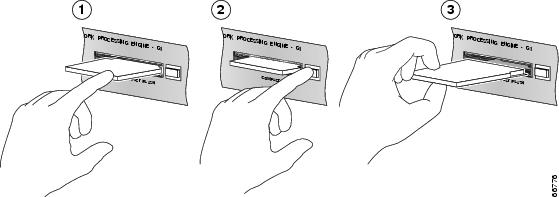
Inserting the CompactFlash Disk
Removing the CompactFlash Disk
Releasing the CompactFlash Disk
Step 1
Step 2
See the Network Processing Engine and Network Services Engine Installation and Configuration document for more information about using the NPE-G1 or NPE-G2.
Figure 2 Installing the GBIC in an NPE-G1
Step 1
Step 2
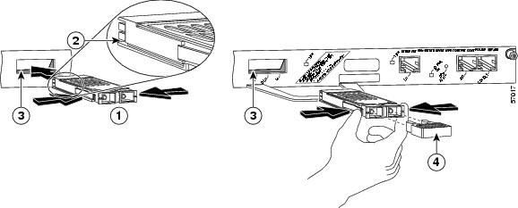
Figure 3 Inserting an SFP Module into the NPE-G2 Gigabit Ethernet Port 0/1

Use the following procedure to install an SFP module in the NPE-G2:
Step 1
Step 2
Note
Step 3
Step 4
Note
Note
See the Cisco 7200 VXR Installation and Configuration Guide for more information.
3 Rack-Mount the Router
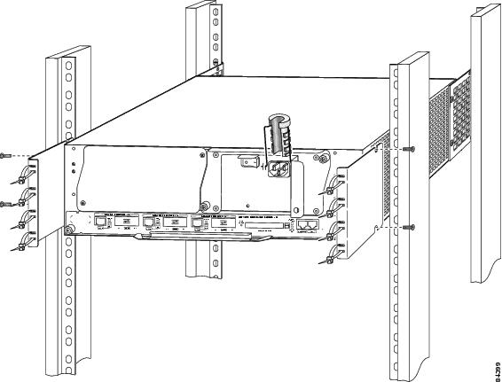
Figure 4 Attaching the Rack-Mount Brackets to the Front of the Chassis
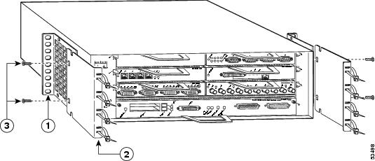
Brackets Front-Mounted—Chassis Protrudes from the Rack
Locate the rack-mount and cable-management brackets and screws and a Number 2 Phillips screwdriver.
Step 1
Go to the "Two-Post or Four-Post Rack Installation" section.
Step 2
If you have an NPE-G1 or NPE-G2 installed, go to the "NPE-G1 and NPE-G2 Rear Cable-Management Brackets on a Front-Mounted Router" section.
If you do not have an NPE-G1 or NPE-G2 installed, go to the "Two-Post or Four-Post Rack Installation" section.
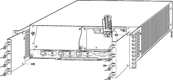
Figure 5 Attaching the Rack-Mount Brackets to the Front of the Chassis—Chassis Recessed
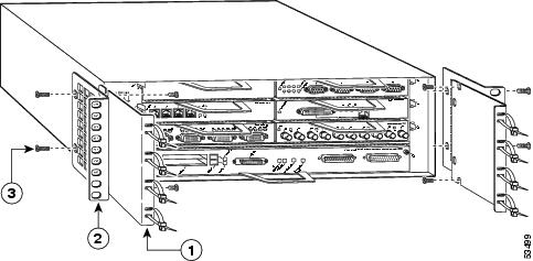
Brackets Front-Mounted—Chassis Recessed in Rack
Locate the rack-mount and cable-management brackets and screws and a Number 2 Phillips screwdriver.
Step 1
Go to the "Two-Post or Four-Post Rack Installation" section.
Step 2
If you have an NPE-G1 or NPE-G2 installed, go to the "NPE-G1 and NPE-G2 Rear Cable-Management Brackets on a Front-Mounted Router" section.
If you do not have an NPE-G1 or NPE-G2 installed, go to the "Two-Post or Four-Post Rack Installation" section.
Figure 6 Installing the Rear Cable-Management Brackets with an NPE-G1 or NPE-G2 Installed—Router Front-Mounted
NPE-G1 and NPE-G2 Rear Cable-Management Brackets on a Front-Mounted Router
If you have an NPE-G1 or NPE-G2 installed, install cable-management brackets on the rear of the router as well as on the front of the router.
Step 1
Step 2
Go to the "Two-Post or Four-Post Rack Installation" section.
Figure 7 Attaching the Rack-Mount Brackets to the Rear of the Chassis—Front Protrudes from the Rack
Rack-mount bracket
Cable-management bracket
M4 x 8-mm Phillips flathead screws
M4 x 8-mm Phillips flathead screws
Brackets Rear-Mounted—Front Protrudes from the Rack
Step 1
Step 2
Step 3
Step 4
Step 5
Step 6
Step 7
If you have an NPE-G1 or NPE-G2 installed, go to the "NPE-G1 or NPE-G2 Rear Cable-Management Brackets on a Rear-Mounted Router" section, or the "NPE-G1 or NPE-G2 Optical Cable-Management Bracket" section.
If you do not have an NPE-G1 or NPE-G2 installed, go to the "Two-Post or Four-Post Rack Installation" section.
Figure 8 Attaching the Rack-Mount Brackets to the Rear of the Chassis—Front Recessed
Rack-mount bracket
Cable-management bracket
M4 x 8-mm Phillips flathead screws
M4 x 8-mm Phillips flathead screws
Brackets Rear-Mounted—Front Recessed in the Rack
Step 1
Step 2
Step 3
Step 4
Step 5
Step 6
Step 7
If you have an NPE-G1 or NPE-G2 installed, go to the "NPE-G1 or NPE-G2 Rear Cable-Management Brackets on a Rear-Mounted Router" section, or the "NPE-G1 or NPE-G2 Optical Cable-Management Bracket" section.
If you do not have an NPE-G1 installed, go to the "Two-Post or Four-Post Rack Installation" section.
Figure 9 Installing the Rear Cable-Management Brackets with the NPE-G1 or NPE-G2—Router Rear-Mounted
NPE-G1 or NPE-G2 Rear Cable-Management Brackets on a Rear-Mounted Router
If you have an NPE-G1 or NPE-G2 installed, install cable-management brackets on the rear of the router as well as on the front of the router.
Step 1
Step 2
Go to the "Two-Post or Four-Post Rack Installation" section.
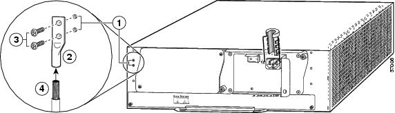
Figure 10 Installing the Optical Cable-Management Bracket
NPE-G1 or NPE-G2 Optical Cable-Management Bracket
Step 1
Step 2
Step 3
Step 4
Step 5
Go to the "Two-Post or Four-Post Rack Installation" section.
Figure 11 Installing the 7200 VXR in a Two-Post and Four-Post Rack
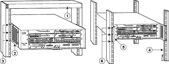
Two-post rack
Four-post rack
Rack-mount bracket
Rack-mount bracket
10-32 x 3/8-inch slotted binderhead screws
10-32 x 3/8-inch slotted binderhead screws
Two-Post or Four-Post Rack Installation
Note
Step 1
Step 2
Step 3
Step 4
Step 5
Step 6
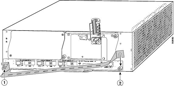
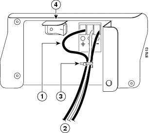
Figure 12 Installing the Chassis Ground Connection
Install the Chassis Ground
Note
Step 1
Step 2
Step 3
Step 4
Step 5
Step 6
Step 7
Step 8
4 Connect the Router to the Network
Figure 13 Connecting the Console and Auxiliary Port Cables
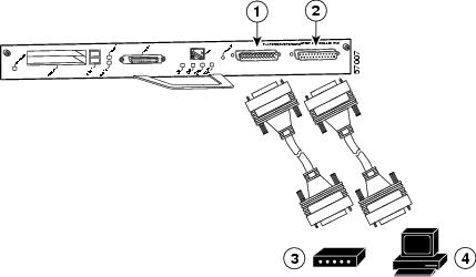
Auxiliary port-DTE-mode; EIA/TIA-232, DTE-DB-25 connector (for modem, CSU/DSU, and so on.)
Modem
Console port-DCE-mode; EIA/TIA-232, DCE-DB-25 connector (for data terminal)
Console terminal
I/O Controller and NPE-G1 or NPE-G2 Console and Auxiliary Port Cable Connections
Note
Step 1
Step 2
Note
For console and auxiliary port pinouts, see the online Cisco 7200 VXR Installation and Configuration Guide,
Chapter 3, "Console Port Signals and Auxiliary Port Signals."
Note
Depending on the I/O controller installed in your Cisco 7200 VXR router, you may have a Gigabit Ethernet port, RJ-45 ports, or no Ethernet port. The following table provides information about the types of ports on different I/O controller models.
Ethernet Port Connections
I/O controllers have the possibility of one or two of three types of Ethernet connections: MII connections and RJ-45 connections for 10/100-Mbps operation, and a Gigabit Interface Converter (GBIC) connection for 1000-Mbps operation. For more information about Ethernet ports, see the online Cisco 7200 VXR Installation and Configuration Guide.
RJ-45 Connections
Warning
To identify the RJ-45 cable type, hold the two ends of the cable next to each other so you can see the colored wires inside the ends. The straight-through wire type has colored wires in the same sequence at both ends.
In the crossover wire type, the first colored wire at the far left is the third colored wire at the other end. The second colored wire at the far left is the sixth colored wire at the other end.
Attach any RJ-45 Ethernet cables to the appropriate connector.
Figure 14 Connecting Optical Fiber Cables

To external 1000BASEX network
2 simplex connectors
1 duplex connector (TX and RX)
RX
To external 1000BASEX network
TX
SFP and GBIC Interface Cables Installation
For more information on cables, specifications, or product numbers, see the Cisco 7200 VXR Installation and Configuration Guide or the Network Processing Engine or Network Services Engine Installation and Configuration.
Note
After the GBIC or SFP is installed in the Gigabit Ethernet port, you must attach the optical fiber cables to the SFP or GBIC. Optical fiber cables are commercially available; they are not available from Cisco Systems.
Warning
Warning
Note
Attach the Multimode and Single-Mode Optical Fiber Cables
Note
Attach the appropriate optical fiber cable directly to the LC-type connector on the SFP, or the SC-type receptacle on the GBIC. You can use either simplex or duplex connectors for most devices.
•
•

Caution
Attach the Mode-Conditioning Patch Cord
A mode-conditioning patch cord can be used with GBIC WS-G5486 or GBIC-LX/LH or SFP-GE-L to allow reliable laser transmission between the single-mode laser source on the GBIC or SFP and a multimode optical fiber cable. To use the mode-conditioning patch cord, follow these steps:
Step 1
Step 2
Note
Port Adapter Cable Connections
The instructions for connecting the cables for each port adapter installed in the Cisco 7200 VXR routers are in the respective online note for each port adapter. The documents are available on the Documentation DVD and on Cisco.com. Reference them from the Cisco 7200 Series Routers Documentation Roadmap at: http://www.cisco.com/en/US/docs/routers/7200/roadmaps/7200_series_doc_roadmap/3512.html
Placing the Cables in the Cable-Management Brackets
Figure 15 Placing Cables in the Cable-Management Brackets
Step 1
Step 2
5 Start and Configure the Router
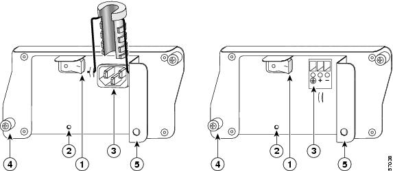
Power Cable Connections
Caution
Warning
Connect AC-Input Power
Note
Figure 16 Connecting the AC Power Cable
Power switch
AC power cable-retention clip
AC power cable
Hole for nylon cable tie
PWR OK LED

Step 1
Step 2
Step 3
a.
b.
Step 4
Step 5
Step 6
Connect DC-Input Power
Note
Warning
Caution
Figure 17 Attaching the DC Power Cables
Step 1
Step 2
Step 3
Step 4
Step 5
Note
Step 6
When securing the ground, +V, and -V DC-input leads to the power supply faceplate, leave a small service loop in the ground lead to ensure that the ground lead is the last lead to disconnect from the power supply if a great deal of strain is placed on all three leads.
Step 7
Important NPE-G1 and NPE-G2 Information
Following is some important NPE-G1 information that you need to know before you power on the router:
•
•
•
•
•
•
•
•
•
•
•
•
Note
Start the System and Perform a Basic Configuration
Step 1
Step 2
Step 3
Caution
Step 4
Note
Step 5
Step 6
Step 7
Note
Before configuring the router, determine whether or not you want to use a management tool such as Cisco Security Device Manager.
Cisco Security Device Manager (SDM), version 1.1, is an optional Java-based device-management tool that allows you to configure LAN interfaces, routing, Network Address Translation (NAT), firewalls, Virtual Private Networks (VPNs), and other features without knowledge of the Cisco command-line interface (CLI). You can configure features such as Access Control Lists (ACLs), routing protocols, and other options using SDMs advanced mode.
Note
SDM is preinstalled on your routers Flash Disk or CompactFlash Disk when it is ordered as part of a VPN bundle or as part of a 7xxx VPN bundle. If your router did not ship with SDM preinstalled, you can download a free copy from the Software Center at Cisco.com at http://ww.cisco.com/kobayashi/sw-center/index.shtm. Because SDM uses a GUI, it requires that you access it from a PC using a supported web browser. Go to the Cisco Router and Security Device Manager (SDM) User Guide for the Cisco 7200 VXR and Cisco 7301 Routers for more information.
Configure the Router
When you start up the router for the first time, the system automatically enters the setup facility, which determines which port adapters are installed and prompts you for configuration information for each one. On the console terminal, after the system displays the system banner and hardware configuration, you will see the following System Configuration Dialog prompt:
--- System Configuration Dialog ---At any point you may enter a questions mark `?' for help.Use ctrl-c to abort configuration dialog at any prompt.Default settings are in square brackets `[]'.continue with configuration dialog? [yes]:
Step 1
You have the option of proceeding with the setup facility to configure the interfaces, or exiting from setup and using configuration commands to configure global (system-wide) and interface-specific parameters. You do not have to configure the interfaces immediately; however, you cannot enable the interfaces or connect them to any networks until you have configured them.
Many of the port adapter LEDs do not go on until you have configured the interfaces. To verify correct operation of each interface, complete the first-time startup procedures and configuration, and then refer to the configuration note for each port adapter for LED descriptions and to check the status of the interfaces.
If the system does not complete each of the steps in the startup procedure, refer to the online Cisco 7200 VXR Installation and Configuration Guide, Appendix A, "Troubleshooting the Installation," for troubleshooting recommendations and procedures.
Note
Perform a Basic Configuration Using the Setup Facility
If you do not plan to use AutoInstall, do not connect the router's serial (WAN) cable to the channel service unit/data service unit (CSU/DSU). If the WAN cable is not connected, the router boots from Flash memory and goes automatically into the setup facility.
Note
If the serial (WAN) cable is connected to the CSU/DSU and the router does not have a configuration stored in NVRAM, the router attempts to run AutoInstall at startup. The router may take several minutes to determine that AutoInstall is not set up to a remote TCP/IP host. Once the router determines that AutoInstall is not configured, it defaults to the setup facility.
Configure Global Parameters
When you first start the setup program, you must configure the global parameters. These parameters are used for controlling system-wide settings. Complete the following steps to enter the global parameters:
Step 1
Step 2
The system boots from Flash memory. After startup, the console screen displays a script and a system banner—after about 30 seconds—similar to the following. When you see this information, you have successfully booted your router:
Restricted Rights LegendUse, duplication, or disclosure by the Government issubject to restrictions as set forth in subparagraph(c) of the Commercial Computer Software - RestrictedRights clause at FAR sec. 52.227-19 and subparagraph(c) (1) (ii) of the Rights in Technical Data and ComputerSoftware clause at DFARS sec. 252.227-7013.cisco Systems, Inc.170 West Tasman DriveSan Jose, California 95134-1706Cisco Internetwork Operating System SoftwareIOS (tm) 7200 Software (C7200-JS-M), Released Version 12.0(19980705:021501)Copyright(c) 1986-1998 by cisco Systems, Inc.Compiled Thu 15-Oct-98 02:20 by xxxxxImage text-base: 0x600088C4, data-base: 0x60FA6000cisco 7206VXR (NPE300) processor with 61440K/20480K bytes of memory.R7000 CPU at 262Mhz, Implementation 39, Rev 1.0, 256KB L2, 2048KB L3 CacheSix slot VXR midplane, Version 2.0Last reset from power-onBridging software.X.25 software, Version 3.0.0.SuperLAT software (copyright 1990 by Meridian Technology Corp).TN3270 Emulation software.8 Ethernet/IEEE 802.3 interface(s)3 FastEthernet/IEEE 802.3 interface(s)125K bytes of non-volatile configuration memory.20480K bytes of Flash PCMCIA card at slot 0 (Sector size 128K).8192K bytes of Flash PCMCIA card at slot 1 (Sector size 128K).4096K bytes of Flash internal SIMM (Sector size 256K).!!Press RETURN to get started!The first two sections of the configuration script (the banner and the installed hardware) appear only at initial system startup. On subsequent uses of the setup facility, the script begins with a System Configuration Dialog as shown in the following example:
--- System Configuration Dialog ---At any point you may enter a question mark '?' for help.Use ctrl-c to abort configuration dialog at any prompt.Default settings are in square brackets '[]'.Step 3
Would you like to enter the initial configuration dialog? [yes]:First, would you like to see the current interface summary? [yes]:In the following example, the summary shows a Cisco 7200 VXR router at first-time startup; that is, nothing is configured:
Any interface listed with OK? value "NO" does not have a valid configurationInterface IP-Address OK? Method Status ProtocolATM1/0 unassigned NO unset down downFastEthernet2/0 unassigned NO unset down downStep 4
Configuring global parameters:Enter host name [Router]:Step 5
The enable secret password is a one-way cryptographic secret password used instead of the enable password
when it exists.
Enter enable secret: barneyThe enable password is used when there is no enable secret password and when using older software and some boot images.Enter enable password: bettyEnter virtual terminal password: fredStep 6
Enter yes or press Return to accept SNMP management; enter no to refuse it:
Configure SNMP Network Management? [yes]:Community string [public]:Step 7
Configure Vines? [no]:Configure LAT? [no]:Configure DECnet? [no]:Configure CLNS? [no]:Configure bridging? [no]:Configure XNS? [no]:Configure Apollo? [no]:Step 8
Configure AppleTalk? [no]: yesMultizone networks? [no]: yesConfigure IPX? [no]: yesStep 9
Configure IP? [yes]:Configure IGRP routing? [yes]:Your IGRP autonomous system number [1]:The following sample display includes a continuous listing of all configuration parameters selected in Step 4 through Step 9. Only IP, IPX, and AppleTalk are the selected protocols for this example.
Configuring global parameters:Enter host name [Router]: routerThe enable secret is a one-way cryptographic secret used instead of the enable password when it exists.Enter enable secret: barneyThe enable password is used when there is no enable secret and when using older software and some boot images.Enter enable password: bettyEnter virtual terminal password: fredConfigure SNMP Network Management? [yes]:Community string [public]:Configure Vines? [no]:Configure LAT? [no]:Configure AppleTalk? [no]: yesMultizone networks? [no]: yesConfigure DECnet? [no]:Configure IP? [yes]:Configure IGRP routing? [yes]:Your IGRP autonomous system number [1]: 15Configure RIP routing? [no]:Configure CLNS? [no]: nConfigure bridging? [no]:Configure IPX? [no]: yesConfigure XNS? [no]:Configure Apollo? [no]:Step 10
Configuration Information for the NPE-G1 or NPE-G2
If the NPE-G1 or NPE-G2 and an I/O controller are both installed in the same system, the console and auxiliary ports on the I/O controller are used and the console and auxiliary ports on the NPE-G1 or NPE-G2 are disabled by Cisco IOS.
Note
If the NPE-G1 or NPE-G2 is used without an I/O controller, the console and auxiliary ports on the NPE-G1 or NPE-G2 are used.
Configure an Auxiliary Port to Receive Console Port Messages for the NPE-G1 or NPE-G2
If you choose to have console port messages routed to the auxiliary port, use the Cisco IOS command terminal monitor on the auxiliary port on which you desire to receive console messages.
Router# terminal monitorConfigure the Native Gigabit Ethernet Interfaces on the NPE-G1 or NPE-G2
The NPE-G1or NPE-G2 reports both the RJ-45 and GBIC interface ports as GigabitEthernet 0/1, GigabitEthernet 0/2, and GigabitEthernet 0/3. Before configuring either port type, you must first use the media-type interface command to select the media type, either the GBIC (gbic) for NPe-G1, SFP (sfp) for NPE-G2, or RJ-45 (rj45) port.
Note
Note
Change the Media Type of the Native Gigabit Ethernet SFP, GBIC, or RJ-45 Ports
To be able to use a particular media port for the NPE-G1 or NPE-G2 or I/O Controller GE/E, use Cisco IOS to select the media type. This is done by using the media-type interface command:
media-type { sfp | gbic | rj45 }
Example:
interface GigabitEthernet 0/1media-type rj45endConfigure the Interface Transmission and Speed Modes for the NPE-G1 or NPE-G2
Step 1
Note
speed { 10 | 100 | 1000 | auto }
duplex { full | half | auto }
The following speed/duplex settings are supported:
Media Type Speed Duplex-------------------------------------------------------RJ45 10, 100, 1000, auto full, half, autoGBIC(1) 1000, auto(2) full, half, auto-------------------------------------------------------a.
b.
When using the GBIC or SFP media, there is also the additional negotiation auto command that is used to enable the IEEE 802.1z Gigabit Ethernet (1000 Mbps) autonegotiation protocol.
Step 2
Note
If you change from the GBIC or SFP to the RJ-45 media type, you must set speed and duplex after you have executed the media-type command to ensure the interface will operate in the correct mode.
The media-type GBIC or media-type SFP mode will always default to 1000 Mbps. Both full-duplex and half-duplex operation are supported in this mode.
Debug the NPE-G1 or NPE-G2
Cisco IOS provides two commands to provide information on your interfaces: show interface GigabitEthernet 0/X (where X is 1, 2, or 3) and show controllers GigabitEthernet 0/1.
The output of the show interface command is useful for determining the current operating mode of the interface (speed/duplex/media-type) and the current interface statistics.
The output of the show controllers command displays more information specific to the I/O controller interface. For example, it shows the detected link status, speed, and duplex, and also determines the current status of autonegotiation and the link partners' abilities (if it is an autonegotiation-capable interface).
The show controllers command also displays the current operating state of the driver and the Ethernet controller hardware. The show controllers command is a very powerful debugging aid, especially for Cisco engineers should you need help in debugging a problem. If you have any problems with your Gigabit Ethernet interfaces, you will need to provide this information to Cisco for analysis.
Reset the Interface on the NPE-G1 or NPE-G2
Should you have a problem with your NPE-G1 or NPE-G2 interface and wish to try and reset it, use the command:
clear interface GigabitEthernet 0/X (where X is 1, 2, or 3)
Clear Counters on the NPE-G1 or NPE-G2
NPE-G1 or NPE-G2 interface counters may be cleared (reset) by using the command:
clear counters GigabitEthernet 0/X (where X is 1, 2, or 3)
This will not reset the interface.
Configure Interfaces
Following are the steps for configuring interfaces to allow communication over a LAN or WAN. To configure the interface parameters, you need your interface network addresses and subnet mask information.
Configure ATM Interfaces
In the following example, an ATM interface in slot 1 is configured for an ATM LAN using IP. Follow these steps to configure an ATM interface:
Step 1
Configuring interface parameters:Configuring interface ATM1/0:Is this interface in use? [yes]:Configure IP on this interface? [yes]:IP address for this interface: 1.1.1.10Number of bits in subnet field [0]:Class C network is 1.1.1.0, 0 subnet bits; mask is /24Step 2
Configure IPX on this interface? [no]: yesIPX network number [2]:Step 3
Configure AppleTalk on this interface? [no]: yesExtended AppleTalk network? [no]: yesAppleTalk starting cable range [0]:
Note
Step 4
Configure Fast Ethernet Interfaces
In the following example, a Fast Ethernet interface in slot 2 is configured for a Fast Ethernet LAN using IP. Follow these steps to configure Fast Ethernet interfaces:
Step 1
Configuring interface parameters:Configuring interface FastEthernet2/0:Is this interface in use? [yes]:Use the 100 Base-TX (RJ-45) connector? [yes]:Operate in full-duplex mode? [no]:Configure IP on this interface? [yes]:IP address for this interface: 1.1.1.20Number of bits in subnet field [0]:Class C network is 1.1.1.0, 0 subnet bits; mask is /24Step 2
Configure IPX on this interface? [no]: yesIPX network number [2]:Step 3
Configure AppleTalk on this interface? [no]: yesExtended AppleTalk network? [no]: yesAppleTalk starting cable range [0]:Step 4
Note
Configure Synchronous Serial Interfaces
Synchronous serial interfaces are configured to allow connection to WANs through a CSU/DSU. In the following example, a serial interface in slot 3 is configured for a WAN connection using IP. Follow these steps to configure synchronous serial interfaces:
Step 1
Configuring interface parameters:Configuring interface serial 3/0:Is this interface in use? [yes]:Configure IP on this interface? [yes]:IP address for this interface: 1.1.1.30Number of bits in subnet field [0]:Class A network is 1.1.1.0, 0 subnet bits; mask is /24Step 2
Configure IPX on this interface? [no]: yesIPX network number [2]:Step 3
Configure AppleTalk on this interface? [no]: yesExtended AppleTalk network? [no]: yesAppleTalk starting cable range [0]:Step 4
Note
The following sample display includes a continuous listing of all interface configuration parameters selected for ATM, Fast Ethernet, and serial interfaces.
Configuring interface parameters:Configuring interface ATM1/0:Is this interface in use? [yes]:Configure IP on this interface? [yes]:IP address for this interface: 1.1.1.10Number of bits in subnet field [0]: 0Class C network is 1.1.1.0, 0 subnet bits; mask is /24Configure IPX on this interface? [yes]:IPX network number [2]:Configure AppleTalk on this interface? [no]: yesExtended AppleTalk network? [no]: yesAppleTalk starting cable range [0]:Configuring interface FastEthernet2/0:Is this interface in use? [yes]:Use the 100 Base-TX (RJ-45) connector? [yes]:Operate in full-duplex mode? [no]:Configure IP on this interface? [yes]:IP address for this interface: 1.1.1.20Number of bits in subnet field [0]:Class C network is 1.1.1.0, 0 subnet bits; mask is /24Configure IPX on this interface? [yes]:IPX network number [2]:Configure AppleTalk on this interface? [no]: yesExtended AppleTalk network? [no]: yesAppleTalk starting cable range [0]:Configuring interface Serial3/0:Is this interface in use? [no]: yesConfigure IP on this interface? [no]: yesConfigure IP unnumbered on this interface? [no]:IP address for this interface: 1.1.1.30Number of bits in subnet field [0]:Class A network is 1.0.0.0, 0 subnet bits; mask is 255.0.0.0Configure IPX on this interface? [no]: yesIPX network number [2]:Configure AppleTalk on this interface? [no]: yesExtended AppleTalk network? [no]:AppleTalk network number [1]:The following configuration command script was created:hostname Routerenable secret 5 $1$u8z3$PMYY8em./8sszhzk78p/Y0enable password bettyline vty 0 4password fredsnmp-server community publicip routingno vines routingipx routingappletalk routingno apollo routingno decnet routingno xns routingno clns routingno bridge 1! Turn off IPX to prevent network conflicts.interface ATM1/0ip address 1.1.1.10 255.0.0.1appletalk cable-range 0-0 0.0appletalk discovery!interface FastEthernet2/0media-type 100BaseXhalf-duplexip address 1.1.1.20 255.0.0.2appletalk cable-range 0-0 0.0appletalk discovery!interface serial3/0ip address 1.1.1.30 255.0.0.3ip route-cache cbusno keepalive!router igrp 15network 1.0.0.0!endUse this configuration? [yes/no]: yesBuilding configuration...Use the enabled mode `configure' command to modify this configuration.Press RETURN to get started!Your router is now minimally configured and ready to use. You can use the setup command if you want to modify the parameters after the initial configuration. To perform more complex configurations, use the configure command.
For information on additional interface configuration and specific system configurations, refer to the modular configuration and modular command reference publications in the Cisco IOS software configuration documentation set that corresponds to the software release installed on your Cisco hardware.
Save the Running Configuration to NVRAM
To store the configuration or changes to your startup configuration in NVRAM, enter the copy running-config startup-config command at the Router# prompt:
Router# copy running-config startup-configUsing this command saves the configuration settings that you created in the router using configuration mode and the setup facility. If you fail to do this, your configuration will be lost the next time you reload the router.
Check the Running Configuration Settings
To check the value of the settings you have entered, enter the show running-config command at the Router# prompt:
Router# show running-configTo review changes you make to the configuration, use the EXEC mode show startup-config command to display the information stored in NVRAM.
View Your System Configuration
You can use the show version (or show hardware) and the show diag commands to display the system hardware (the network processing engine or network services engine and the number of interfaces installed), the software version, the names and sources of configuration files, and the boot images. Use the show diag command to determine what type of port adapters and I/O controller are installed.
For specific information on the show version, show diag, and other commands, refer to the modular configuration and modular command reference publications in the Cisco IOS software configuration documentation set that corresponds to the software release installed on your Cisco hardware.
Perform Complex Configurations
After you have installed your Cisco 7200 VXR router hardware and minimally configured the system, you might need to perform more complex configurations, which are beyond the scope of this publication.
For specific information on system and interface configuration, refer to the modular configuration and modular command reference publications in the Cisco IOS software configuration documentation set that corresponds to the software release installed on your Cisco hardware. These publications contain additional information on using the configure command.
Replace or Recover a Lost Password
See the Cisco 7200 VXR Installation and Configuration Guide, Chapter 4, "Observing System Startup and Performing a Basic Configuration" for instructions. It is possible to recover the enable or console login password. The enable secret password is encrypted and must be replaced with a new enable secret password.
6 After Installation
This section contains hardware replacement instructions. The PC card or Flash memory card, CompactFlash Disk, Flash Disk, GBIC, SFP, and port adapters support online insertion and removal (OIR).
These topics are covered in this section:
•
•
•
•
•
Note
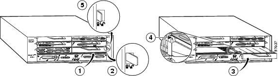
Replace the Network Processing Engine or Network Services Engine
Figure 18 Replacing the Network Processing Engine or Network Services Engine
Caution
Step 1
Step 2
Step 3
Step 4
Note
Step 5
Step 6
Step 7
Step 8
See the Network Processing Engine or Network Services Engine Installation and Configuration publication at http://www.cisco.com/en/US/docs/routers/7200/install_and_upgrade/network_process_engine_install_config/npense.html.
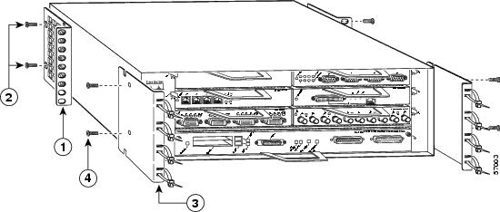
Replace the I/O Controller
Figure 19 Replacing the I/O Controller
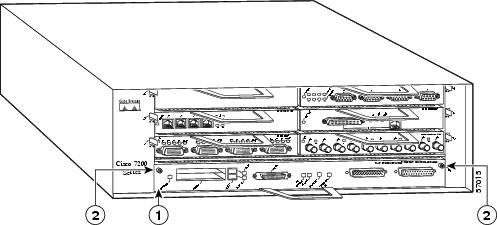
Note
Step 1
Step 2
Step 3
Step 4
Note
Step 5
Step 6
Step 7
Step 8
Step 9
Step 10
See the Input/Output Controller Replacement Instructions publication at: http://www.cisco.com/en/US/docs/routers/7200/install_and_upgrade/7200_i.o_controller_install/4447io.html
Replace the PC Card, Flash Memory Card, Flash Disk, CompactFlash Disk, or USB Token
Figure 20 Replacing the PC Card, Flash Memory Card, Flash Disk, or CompactFlash Disk
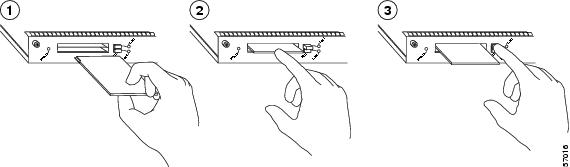
Insert the PC Card or Flash memory card, CompactFlash Disk or Flash Disk
Press the ejector button
Insertion complete—PC Card or Flash memory card, CompactFlash Disk or Flash Disk protrudes
Note
Step 1
Step 2
To replace the CompactFlash Disk in the NPE-G1, see the "Prepare for Installation" section.
Also see Using the Flash Disk at http://www.cisco.com/en/US/docs/routers/7200/install_and_upgrade/flash_disk_install_config/6452fd.html, and Memory Replacement Instructions for the Network Processing Engine or Network Services Engine and I/O Controller at http://www.cisco.com/en/US/docs/routers/7200/install_and_upgrade/npe-nse_memory_install/memory.html.
Replace the Gigabit Interface Converter
Figure 21 Replacing the GBIC
Step 1
Step 2
Step 3
The GBIC is keyed so that it cannot be inserted incorrectly.
Step 4
Step 5
Replace the SFP-NPE-G2
Figure 22 Inserting an SFP Module into the NPE-G2 Gigabit Ethernet Port 0/1
Use the following procedure to install an SFP module in the NPE-G2:
Step 1
Step 2
Note
Step 3
Step 4
Installing a USB Flash Memory Module or eToken—NPE-G2
Figure 23 Connecting a USB Flash Memory Module to a Router USB Port
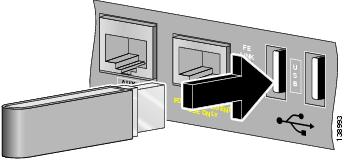
To connect a Cisco USB Flash memory module or the Aladdin USB eToken Pro key to the NPE-G2 USB port, simply insert the module into the port as shown in Figure 23. The Flash memory module can be inserted in only one way, and can be inserted or removed regardless of whether the router is powered up or not.
Caution
Note
Note
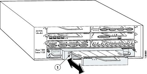
Replace a Port Adapter or Service Adapter
Figure 24 Replacing a Port Adapter
Port adapter in place
Slot guide
Port adapter lever in unlocked position
Port adapter lever in locked position
Port adapter partially removed or installed
Note
Step 1
Note
Step 2
Step 3
Step 4
Step 5
Step 6
For port adapter documentation, see the Cisco 7200 Series Routers Port Adapter Documentation Documentation Roadmap.
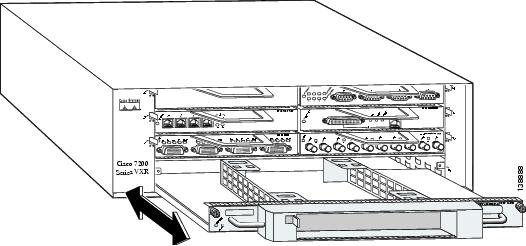
Replace the Port Adapter Jacket Card
Note
Figure 25 Removing a Port Adapter
Step 1
Step 2
Step 3
Step 4
Step 5
Figure 26 Removing the Port Adapter Jacket Card
Note
Step 6
Step 7
Step 8
Step 9
Step 10
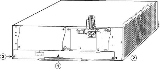
Replace the Power Supply
Figure 27 Replacing the Power Supply
Caution
Caution
Caution
Step 1
Step 2
Step 3
Step 4
Step 5
Step 6
Note
7 Cisco Product Security Overview
Cisco provides a free online Security Vulnerability Policy portal at this URL:
http://www.cisco.com/en/US/products/products_security_vulnerability_policy.html
From this site, you can perform these tasks:
•
•
•
A current list of security advisories and notices for Cisco products is available at this URL:
If you prefer to see advisories and notices as they are updated in real time, you can access a Product Security Incident Response Team Really Simple Syndication (PSIRT RSS) feed from this URL:
http://www.cisco.com/en/US/products/products_psirt_rss_feed.html
Reporting Security Problems in Cisco Products
Cisco is committed to delivering secure products. We test our products internally before we release them, and we strive to correct all vulnerabilities quickly. If you think that you might have identified a vulnerability in a Cisco product, contact PSIRT:
•
An emergency is either a condition in which a system is under active attack or a condition for which a severe and urgent security vulnerability should be reported. All other conditions are considered nonemergencies.
•
In an emergency, you can also reach PSIRT by telephone:
•
•
Tip
Never use a revoked or an expired encryption key. The correct public key to use in your correspondence with PSIRT is the one linked in the Contact Summary section of the Security Vulnerability Policy page at this URL:
http://www.cisco.com/en/US/products/products_security_vulnerability_policy.html
The link on this page has the current PGP key ID in use.
8 Obtaining Technical Assistance
Cisco Technical Support provides 24-hour-a-day award-winning technical assistance. The Cisco Technical Support & Documentation website on Cisco.com features extensive online support resources. In addition, if you have a valid Cisco service contract, Cisco Technical Assistance Center (TAC) engineers provide telephone support. If you do not have a valid Cisco service contract, contact your reseller.
Cisco Technical Support & Documentation Website
The Cisco Technical Support & Documentation website provides online documents and tools for troubleshooting and resolving technical issues with Cisco products and technologies. The website is available 24 hours a day, at this URL:
http://www.cisco.com/techsupport
Access to all tools on the Cisco Technical Support & Documentation website requires a Cisco.com user ID and password. If you have a valid service contract but do not have a user ID or password, you can register at this URL:
http://tools.cisco.com/RPF/register/register.do
Note
Submitting a Service Request
Using the online TAC Service Request Tool is the fastest way to open S3 and S4 service requests. (S3 and S4 service requests are those in which your network is minimally impaired or for which you require product information.) After you describe your situation, the TAC Service Request Tool provides recommended solutions. If your issue is not resolved using the recommended resources, your service request is assigned to a Cisco engineer. The TAC Service Request Tool is located at this URL:
http://www.cisco.com/techsupport/servicerequest
For S1 or S2 service requests, or if you do not have Internet access, contact the Cisco TAC by telephone. (S1 or S2 service requests are those in which your production network is down or severely degraded.) Cisco engineers are assigned immediately to S1 and S2 service requests to help keep your business operations running smoothly.
To open a service request by telephone, use one of the following numbers:
Asia-Pacific: +61 2 8446 7411 (Australia: 1 800 805 227)
EMEA: +32 2 704 55 55
USA: 1 800 553-2447For a complete list of Cisco TAC contacts, go to this URL:
http://www.cisco.com/techsupport/contacts
Definitions of Service Request Severity
To ensure that all service requests are reported in a standard format, Cisco has established severity definitions.
Severity 1 (S1)—An existing network is down, or there is a critical impact to your business operations. You and Cisco will commit all necessary resources around the clock to resolve the situation.
Severity 2 (S2)—Operation of an existing network is severely degraded, or significant aspects of your business operations are negatively affected by inadequate performance of Cisco products. You and Cisco will commit full-time resources during normal business hours to resolve the situation.
Severity 3 (S3)—Operational performance of the network is impaired, while most business operations remain functional. You and Cisco will commit resources during normal business hours to restore service to satisfactory levels.
Severity 4 (S4)—You require information or assistance with Cisco product capabilities, installation, or configuration. There is little or no effect on your business operations.
 Feedback
Contact Cisco
- Open a Support Case

- (Requires a Cisco Service Contract)