Table Of Contents
7.2.3 Circuit Protection Types
7.4 VT Tunnels and Aggregation Points
7.6 Go-and-Return Path Protection Routing
7.7 Virtual Concatenated Circuits
7.7.3 Link Capacity Adjustment
7.9.4 Two-Circuit Bridge and Roll
Circuits and Tunnels
Note
The terms "Unidirectional Path Switched Ring" and "UPSR" may appear in Cisco literature. These terms do not refer to using Cisco ONS 15xxx products in a unidirectional path switched ring configuration. Rather, these terms, as well as "Path Protected Mesh Network" and "PPMN," refer generally to Cisco's path protection feature, which may be used in any topological network configuration. Cisco does not recommend using its path protection feature in any particular topological network configuration.
This chapter explains Cisco ONS 15310-CL synchronous transport signal (STS) and Virtual Tributary (VT) circuits and VT and data communications channel (DCC) tunnels. To provision circuits and tunnels, refer to the Cisco ONS 15310-CL Procedure Guide.
Chapter topics include:
•
•
•
7.1 Overview
You can create circuits across and within ONS 15310-CL nodes and assign different attributes to circuits. For example, you can:
•
•
•
•
•
•
•
•
•
For the CE-100T-8 or ML-100T-8 card, you can provision circuits either before or after the cards are installed if the slots are provisioned. For the 15310-CL-CTX card, you must preprovision the small form-factor pluggables (SFPs) (called pluggable port modules [PPMs] in CTC) before you can create an optical circuit. However, circuits do not carry traffic until the cards and SFPs are installed and the ports are In-Service and Normal (IS-NR); Out-of-Service and Autonomous, Automatic In-Service (OO-AU,AINS); or Out-of-Service and Management, Maintenance (OOS-MA,MT).
7.2 Circuit Properties
You can view information about circuits in the ONS 15310-CL Circuits window, which appears in network, node, and card view. The Circuits window shows the following information:
•
•
•
•
•
•
•
•
•
•
7.2.1 Circuit Status
The circuit statuses that appear in the Circuit window Status column are generated by Cisco Transport Controller (CTC) based on conditions along the circuit path. Table 7-1 shows the statuses that can appear in the Status column.
Table 7-1 ONS 15310-CL Circuit Status
CREATING
CTC is creating a circuit.
DISCOVERED
CTC created a circuit. All components are in place and a complete path exists from circuit source to destination.
DELETING
CTC is deleting a circuit.
PARTIAL
A CTC-created circuit is missing a cross-connect or network span or a complete path from source to destination(s) does not exist.
In CTC, circuits are represented using cross-connects and network spans. If a network span is missing from a circuit, the circuit status is PARTIAL. However, a PARTIAL status does not necessarily mean a circuit traffic failure has occurred, because traffic might flow on a protect path.
Network spans are in one of two states: up or down. On CTC circuit and network maps, up spans appear as green lines, and down spans appear as gray lines. If a failure occurs on a network span during a CTC session, the span remains on the network map but its color changes to gray to indicate that the span is down. If you restart your CTC session while the failure is active, the new CTC session cannot discover the span and its span line does not appear on the network map.
Subsequently, circuits routed on a network span that goes down appear as DISCOVERED during the current CTC session, but appear as PARTIAL to users who log in after the span failure.
DISCOVERED_TL1
A TL1-created circuit or a TL1-like CTC-created circuit is complete. A complete path from source to destinations exists.
PARTIAL_TL1
A TL1-created circuit or a TL1-like CTC-created circuit is missing a cross-connect or circuit span (network link), and a complete path from source to destinations does not exist.
CONVERSION_PENDING
An existing circuit in a topology upgrade is set to this status. The circuit returns to the DISCOVERED status when the topology upgrade is complete. For more information about in-service topology upgrades, see Chapter 8, "SONET Topologies and Upgrades."
PENDING_MERGE
Any new circuits created to represent an alternate path in a topology upgrade are set to this status to indicate that it is a temporary circuit. These circuits can be deleted if a topology upgrade fails. For more information about in-service topology upgrades, see Chapter 8, "SONET Topologies and Upgrades."
7.2.2 Circuit States
The circuit service state is an aggregate of the cross-connect states within the circuit.
•
•
•
You can assign a state to circuit cross-connects at two points:
•
•
During circuit creation, you can apply a service state to the drop ports in a circuit; however, CTC does not apply a requested state other than IS-NR to drop ports if:
•
•
•
•
Circuits do not use the soak timer, but ports do. The soak period is the amount of time that the port remains in the OOS-AU,AINS service state after a signal is continuously received. When the cross-connects in a circuit are in the OOS-AU,AINS service state, the ONS 15310-CL monitors the cross-connects for an error-free signal. It changes the state of the circuit from OOS to IS or to OOS-PARTIAL as each cross-connect assigned to the circuit path is completed. This allows you to provision a circuit using TL1, verify its path continuity, and prepare the port to go into service when it receives an error-free signal for the time specified in the port soak timer. Two common examples of state changes you see when provisioning circuits using CTC are:
•
•
To find the remaining port soak time, choose the Maintenance > AINS Soak tabs in card view and click the Retrieve button. If the port is in the OOS-AU,AINS service state and has a good signal, the Time Until IS column shows the soak count down status. If the port is OOS-AU,AINS and has a bad signal, the Time Until IS column indicates that the signal is bad. You must click the Retrieve button to obtain the latest time value.
For more information about port and cross-connect service states, see Appendix B, "Administrative and Service States."
7.2.3 Circuit Protection Types
The Protection column on the Circuit window shows the card (line) and SONET topology (path) protection used for the entire circuit path. Table 7-2 shows the protection type indicators that you see in this column.
7.2.4 Edit Circuits Window
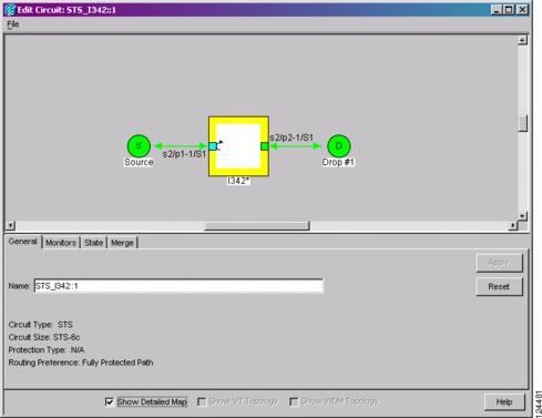
Use the Edit Circuits window to view general circuit information, create monitor circuits, and change a circuit state. For path protection circuits, use the Edit Circuits window to change path protection selectors and switch protection paths. Selectors appear as pentagons on the detailed circuit map.
From the UPSR Selectors subtab in the Edit Circuits window, you can:
•
•
•
•
•
Note
In the UPSR Switch Counts subtab, you can:
•
•
From the Edit Circuits window, you can display a detailed circuit map by checking Show Detailed Map. The detailed map allows you to view information about ONS 15310-CL circuits. Routing information that appears includes:
•
•
•
•
•
Alarms and states can also be viewed on the circuit map, including:
•
•
•
•
•
•
•
By default, the working path on the detailed circuit map is indicated by a green bidirectional arrow, and the protect path is indicated by a purple bidirectional arrow. Source and destination ports are shown as circles with an S and D. Port states are indicated by colors, shown in Table 7-3.
Table 7-3 Port State Color Indicators
Green
IS-NR
Gray
OOS-MA,DSBLD
Purple
OOS-AU,AINS
Light blue
OOS-MA,MT
Notations within or next to the squares or selector pentagons on each node indicate switches and other conditions. For example:
•
•
•
•
Figure 7-1 Terminal Loopback in the Edit Circuits Window
Move the mouse cursor over nodes, ports, and spans to see tooltips with information including the number of alarms on a node (organized by severity), a port's service state, and the protection topology.
Right-click a node, port, or span on the detailed circuit map to initiate certain circuit actions:
•
•
•
7.3 VT1.5 Bandwidth
The 15310-CL-CTX card performs port-to-port time-division multiplexing (TDM). Because VT1.5 multiplexing is STS-based, understanding how VT1.5 circuits use the 15310-CL-CTX VT matrix resources is necessary to avoid unexpected depletion of VT matrix capacity. The key VT matrix principles are as follows:
•
•
The 15310-CL-CTX card can map up to 24 STSs for VT1.5 traffic. Because one STS can carry 28 VT1.5s, the 15310-CL-CTX card can terminate up to 672 VT1.5s or 336 VT1.5 cross-connects. However, to terminate 336 VT1.5 cross-connects, each STS mapped for VT1.5 traffic must carry 28 VT1.5 circuits. If you assign each VT1.5 circuit to a different STS, the 15310-CL-CTX card VT1.5 cross-connect capacity is reached after you create 12 VT1.5 circuits.
7.4 VT Tunnels and Aggregation Points
To maximize 15310-CL-CTX VT1.5 cross-connect resources, you can tunnel VT1.5 circuits through ONS 15310-CL nodes. VT1.5 tunnels do not use VT matrix capacity at ONS 15310-CL pass-through nodes, thereby freeing the 15310-CL-CTX card cross-connect resources for other VT1.5 circuits.
VT aggregation points (VAPs) allow you to provision circuits from multiple VT1.5 sources to a single STS destination. Like circuits, a VAP has a source and a destination. The source is the STS grooming end, the node where the VT1.5 circuits are aggregated into a single STS. The VAP STS must be an OC-N. VT matrix resources are not used on the VAP source node, which is the key advantage of VAPs. The VAP destination is the node where the VT1.5 circuits originate. Circuits can originate on any ONS 15310-CL card or port.
7.5 DCC Tunnels
Each SONET frame provides four DCCs for network element (NE) Operations, Administration, Maintenance, and Provisioning (OAM&P): one on the SONET Section layer (DCC1) and three on the SONET Line layer (DCC2, DCC3, DCC4). The ONS 15310-CL uses the Section DCC (SDCC) or Line DCC (LDCC) for ONS 15310-CL management and provisioning. When multiple DCC channels exist between two neighboring nodes, the ONS 15310-CL balances traffic over the existing DCC channels using a load- balancing algorithm. This algorithm chooses a DCC for packet transport by considering packet size and DCC utilization. You can tunnel third-party SONET equipment across ONS 15310-CL networks using one of two tunneling methods, a traditional DCC tunnel or an IP-encapsulated tunnel.
7.5.1 Traditional DCC Tunnels
In traditional DCC tunnels, you can use the three available channels of the LDCC and/or the single channel of the SDCC, when not used for ONS 15310-CL DCC terminations, to tunnel third-party SONET equipment across ONS networks. A DCC tunnel endpoint is defined by slot, port, and DCC channel. You can connect any of the four available channels to any other available channel. To create a DCC tunnel, you connect the tunnel endpoints from one ONS 15310-CL optical port to another.
Table 7-4 shows the DCC tunnels that you can create.
Table 7-4 DCC Tunnels
DCC1
Section
D1 to D3
Yes
DCC2
Line
D4 to D6
Yes
DCC3
Line
D7 to D9
Yes
DCC4
Line
D10 to D12
Yes
When you create DCC tunnels, keep the following guidelines in mind:
•
•
7.5.2 IP-Encapsulated Tunnels
An IP-encapsulated tunnel puts an SDCC in an IP packet at a source node and dynamically routes the packet to a destination node. To compare traditional DCC tunnels with IP-encapsulated tunnels, a traditional DCC tunnel is configured as one dedicated path across a network and does not provide a failure recovery mechanism if the path is down. An IP-encapsulated tunnel is a virtual path, which adds protection when traffic travels between different networks.
IP-encapsulated tunneling has the potential of flooding the DCC network with traffic resulting in a degradation of performance for CTC. The data originating from an IP tunnel can be throttled to a user-specified rate, which is a percentage of the total SDCC bandwidth.
Each ONS 15310-CL supports one IP-encapsulated tunnel. You can convert a traditional DCC tunnel to an IP-encapsulated tunnel or an IP-encapsulated tunnel to a traditional DCC tunnel. Only tunnels in the Discovered status can be converted.
Caution
7.6 Go-and-Return Path Protection Routing
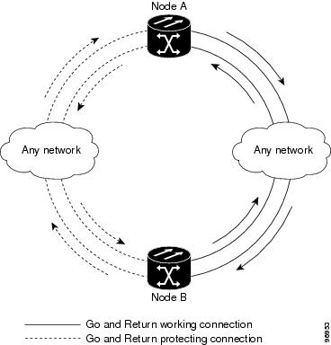
The go-and-return path protection routing option allows you to route the path protection working path on one fiber pair and the protect path on a separate fiber pair (Figure 7-2). The working path will always be the shortest path. If a fault occurs, neither the working and protection fibers are affected. This feature only applies to bidirectional path protection circuits. The go-and-return option appears on the Circuit Attributes page of the Circuit Creation wizard.
Figure 7-2 Path Protection Go-and-Return Routing
7.7 Virtual Concatenated Circuits
Virtual concatenated (VCAT) circuits, also called VCAT groups (VCGs), transport traffic using noncontiguous TDM time slots, avoiding the bandwidth fragmentation problem that exists with contiguous concatenated (CCAT) circuits. The ONS 15310-CL cards that support VCAT circuits are the CE-100T-8 and ML-100T-8 cards.
In a VCAT circuit, circuit bandwidth is divided into smaller circuits called VCAT members. The individual members act as independent TDM circuits. All VCAT members should be the same size and must originate/terminate at the same end points.
7.7.1 VCAT Circuit States
The state of a VCAT circuit is an aggregate of its member circuits. You can view whether a VCAT member is In Group or Out of Group in the VCAT State column in the Edit Circuits window.
•
•
•
•
7.7.2 VCAT Member Routing
The automatic and manual routing selection applies to the entire VCAT circuit, that is, all members are manually or automatically routed. Bidirectional VCAT circuits are symmetric, which means that the same number of members travel in each direction. With automatic routing, you can specify the constraints for individual members; with manual routing, you can select different spans for different members.
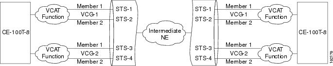
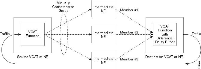
Two types of automatic and manual routing are available for VCAT members on CE-100T-8 and ML-100T-8 cards: common fiber routing and split fiber routing. In common fiber routing, all VCAT members travel on the same fibers, which eliminates delay between members. Three protection options are available for common fiber routing: Fully Protected, PCA, and Unprotected. Split fiber routing allows the individual members to be routed on different fibers or each member to have different routing constraints. This mode offers the greatest bandwidth efficiency and also the possibility of differential delay, which is handled by the buffers on the terminating cards or ports. Three protection options are available for split fiber routing: Fully Protected, Unprotected, and DRI. In both common fiber and split fiber routing, each member can use a different protection scheme; however, for common fiber routing, CTC checks the combination to make sure that a valid route exists. If it does not, the user must modify the protection type.
In both common fiber and split fiber routing, intermediate nodes treat the VCAT members as normal circuits that are independently routed and protected by the SONET network. At the terminating nodes, these member circuits are multiplexed into a contiguous stream of data. Figure 7-3 shows an example of common fiber routing.
Figure 7-3 VCAT Common Fiber Routing
Figure 7-4 shows an example of split fiber routing.
Figure 7-4 VCAT Split Fiber Routing
7.7.3 Link Capacity Adjustment
The CE-100T-8 and ML-100T-8 cards support Link Capacity Adjustment Scheme (LCAS), which is a signaling protocol that allows dynamic bandwidth adjustment of VCAT circuits. When a member fails, LCAS temporarily removes the failed member from the VCAT circuit for the duration of the failure, leaving the remaining members to carry the traffic. When the failure clears, the member circuit is automatically added back into the VCAT circuit. You can select LCAS during VCAT circuit creation.
Note
SW-LCAS is a limited form of LCAS that allows the VCAT circuit to adapt to member failures and keep traffic flowing at a reduced bandwidth. SW-LCAS is necessary when interoperating with the ONS 15454 ML-Series cards. SW-LCAS uses legacy SONET failure indicators like path alarm indication signal (AIS-P) and path remote defect indication (RDI-P) to detect member failure. You can select SW-LCAS during VCAT circuit creation.
In addition, you can create non-LCAS VCAT circuits, which do not use LCAS or SW-LCAS. While LCAS and SW-LCAS member cross-connects can be in different service states, all In Group non-LCAS members must have cross-connects in the same service state. A non-LCAS circuit can mix Out of Group and In Group members, as long as the In Group members are in the same service state. Non-LCAS members do not support the OOS-MA,OOG service state; to put a non-LCAS member in the Out of Group VCAT state, use OOS-MA,DSBLD.
Note
7.7.4 VCAT Circuit Size
Table 7-5 lists supported VCAT circuit rates and the number of members for each card.
Table 7-5 ONS 15310-CL Card VCAT Circuit Rates and Members
CE-100T-8 1
VT1.5
1-64
STS-1
1-3
ML-100T-8 1
STS-1
1-2
1 A VCAT circuit with an ONS 15310-CL CE-100T-8 or ML-100T-8 card as a source or destination and an ONS 15454 ML-Series card as a source or destination can have only two members.
Use the Members tab in the Edit Circuit window to add or delete members from a VCAT circuit. The capability to add or delete members depends on whether the VCAT circuit is LCAS, SW-LCAS, or non-LCAS:
•
•
•
Table 7-6 summarizes the VCAT capabilities for the CE-100T-8 and ML-100T-8 cards.
Table 7-6 ONS 15310-CL VCAT Card Capabilities
CE-100T-8
LCAS
Yes
Yes
Yes
SW-LCAS
No
No
No
Non-LCAS
Yes1
Yes1
No
ML-100T-8
LCAS
Yes
Yes
Yes
SW-LCAS
No
No
No
Non-LCAS
No
No
No
1 For CE-100T-8 cards, you can add or delete members after creating a VCAT circuit with no protection. During the time it takes to add or delete members (from seconds to minutes), the entire VCAT circuit will be unable to carry traffic.
7.8 Path Trace
SONET J1 and J2 path trace are repeated, fixed-length strings composed of 64 consecutive bytes. You can use the strings to monitor interruptions or changes to circuit traffic. Table 7-7 shows the ONS 15310-CL cards that support J1 and/or J2 path trace.
If the string received at a circuit drop port does not match the string that the port expects to receive, an alarm is raised. Two path trace modes are available:
•
•
7.9 Bridge and Roll
The CTC Bridge and Roll wizard reroutes live traffic without interrupting service. The bridge process takes traffic from a designated "roll from" facility and establishes a cross-connect to the designated "roll to" facility. When the bridged signal at the receiving end point is verified, the roll process creates a new cross-connect to receive the new signal. When the roll completes, the original cross-connects are released. You can use the bridge and roll feature for maintenance functions such as card or facility replacement, or for load balancing. You can perform a bridge and roll on the following ONS platforms: ONS 15600, ONS 15454, ONS 15454 SDH, ONS 15327, and ONS 15310-CL.
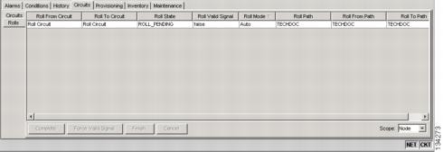
7.9.1 Rolls Window
The Rolls window lists information about a rolled circuit before the roll process is complete. You can access the Rolls window by clicking the Circuits > Rolls tabs in either network or node view. Figure 7-5 shows the Rolls window.
Figure 7-5 Rolls Window
The Rolls window information includes:
•
•
•
•
•
CTC implements a roll mode at the circuit level. TL1 implements a roll mode at the cross-connect level. If a single roll is performed, CTC and TL1 behave the same. If a dual roll is performed, the roll mode specified in CTC might be different than the roll mode retrieved in TL1. For example, if you select Automatic, CTC coordinates the two rolls to minimize possible traffic hits by using the Manual mode behind the scenes. When both rolls have a good signal, CTC signals the nodes to complete the roll.
–
–
•
•
•
•
•
•
•
7.9.2 Roll Status
Table 7-8 lists the roll statuses. You can only reroute circuits that have a DISCOVERED status. (See Table 7-1 for a list of circuit statuses.) You cannot reroute circuits that are in the ROLL_PENDING status.
7.9.3 Single and Dual Rolls
Circuits have an additional layer of roll types: single and dual. A single roll on a circuit is a roll on one of its cross-connects. Use a single roll to:
•
•
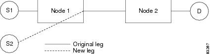
In Figure 7-6, you can select any available STS on Node 1 for a new source.
Figure 7-6 Single Source Roll
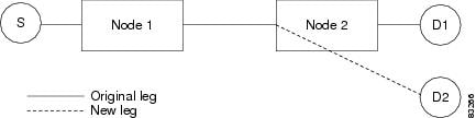
In Figure 7-7, you can select any available STS on Node 2 for a new destination.
Figure 7-7 Single Destination Roll
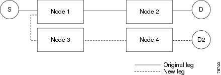
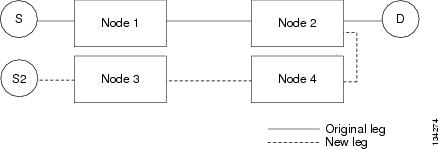
Figure 7-8 shows one circuit rolling onto another circuit at the destination. The new circuit has cross-connects on Node 1, Node 3, and Node 4. CTC deletes the cross-connect on Node 2 after the roll.
Figure 7-8 Single Roll from One Circuit to Another Circuit (Destination Changes)
Figure 7-9 shows one circuit rolling onto another circuit at the source.
Figure 7-9 Single Roll from One Circuit to Another Circuit (Source Changes)
Note
A dual roll involves two cross-connects. It allows you to reroute intermediate segments of a circuit, but keep the original source and destination. If the new segments require new cross-connects, use the Bridge and Roll wizard or create a new circuit and then perform a roll.
Dual rolls have several constraints:
•
•
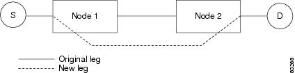
Figure 7-10 illustrates a dual roll on the same circuit.
Figure 7-10 Dual Roll to Reroute a Link
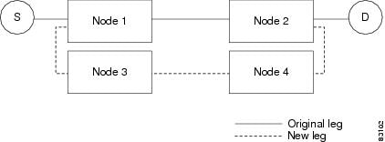
Figure 7-11 illustrates a dual roll involving two circuits.
Figure 7-11 Dual Roll to Reroute to a Different Node
Note
7.9.4 Two-Circuit Bridge and Roll
When using the bridge and roll feature to reroute traffic using two circuits, the following constraints apply:
•
•
•
•
7.9.5 Protected Circuits
CTC allows you to roll the working or protect path regardless of which path is active. You can upgrade an unprotected circuit to a fully protected circuit or downgrade a fully protected circuit to an unprotected circuit with the exception of a path protection circuit. When using bridge and roll on path protection circuits, you can roll the source or destination or both path selectors in a dual roll. However, you cannot roll a single path selector.
7.10 Merged Circuits
A circuit merge combines a single selected circuit with one or more circuits. You can merge VT tunnels, VAP circuits, orderwire and user data channel (UDC) overhead circuits, CTC-created traffic circuits, and TL1-created traffic circuits. To merge circuits, you choose a master circuit on the CTC Circuits tab. Then, you choose the circuits that you want to merge with the master circuit on the Merge tab in the Edit Circuits window. The Merge tab shows only the circuits that are available for merging with the master circuit:
•
•
•
•
•
•
If all connections from the master circuit and all connections from the merged circuits align to form one complete circuit, the merge is successful. If all connections from the master circuit and some, but not all, connections from the other circuits align to form a single complete circuit, CTC notifies you and gives you the chance to cancel the merge process. If you choose to continue, the aligned connections merge successfully into the master circuit, and the unaligned connections remain in the original circuits.
All connections from the master circuit and at least one connection from the other selected circuits must be used in the resulting circuit for the merge to succeed. If a merge fails, the master circuit and all other circuits remain unchanged. When the circuit merge completes successfully, the resulting circuit retains the name of the master circuit.
7.11 Reconfigured Circuits
You can reconfigure multiple circuits, which is typically necessary when a large number of circuits are in the PARTIAL status. When reconfiguring multiple circuits, the selected circuits can be any combination of DISCOVERED, PARTIAL, DISCOVERED_TL1, or PARTIAL_TL1 circuits. You can reconfigure tunnels, VAP circuits, CTC-created circuits, and TL1-created circuits.
Use the CTC Tools > Circuits > Reconfigure Circuits command to reconfigure selected circuits. During reconfiguration, CTC reassembles all connections of the selected circuits into circuits based on path size, direction, and alignment. Some circuits might merge and others might split into multiple circuits. If the resulting circuit is a valid circuit, it appears as a DISCOVERED circuit. Otherwise, the circuit appears as a PARTIAL or PARTIAL_TL1 circuit.
Note