Feedback
Table Of Contents
Routing Between VLANs Overview
Integrated Routing and Bridging
ATM LANE Fast Simple Server Replication Protocol
Routing Between VLANs Overview
This chapter provides an overview of VLANs. It describes the encapsulation protocols used for routing between VLANs and provides some basic information about designing VLANs. It contains the following sections:
What Is a VLAN?
A VLAN is a switched network that is logically segmented on an organizational basis, by functions, project teams, or applications rather than on a physical or geographical basis. For example, all workstations and servers used by a particular workgroup team can be connected to the same VLAN, regardless of their physical connections to the network or the fact that they might be intermingled with other teams. Reconfiguration of the network can be done through software rather than by physically unplugging and moving devices or wires.
A VLAN can be thought of as a broadcast domain that exists within a defined set of switches. A VLAN consists of a number of end systems, either hosts or network equipment (such as bridges and routers), connected by a single bridging domain. The bridging domain is supported on various pieces of network equipment; for example, LAN switches that operate bridging protocols between them with a separate bridge group for each VLAN.
VLANs are created to provide the segmentation services traditionally provided by routers in LAN configurations. VLANs address scalability, security, and network management. Routers in VLAN topologies provide broadcast filtering, security, address summarization, and traffic flow management. None of the switches within the defined group will bridge any frames, not even broadcast frames, between two VLANs. Several key issues described in the following sections need to be considered when designing and building switched LAN internetworks:
LAN Segmentation
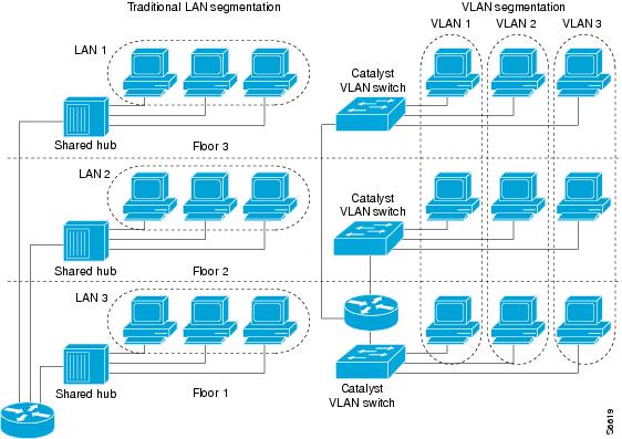
VLANs allow logical network topologies to overlay the physical switched infrastructure such that any arbitrary collection of LAN ports can be combined into an autonomous user group or community of interest. The technology logically segments the network into separate Layer 2 broadcast domains whereby packets are switched between ports designated to be within the same VLAN. By containing traffic originating on a particular LAN only to other LANs in the same VLAN, switched virtual networks avoid wasting bandwidth, a drawback inherent to traditional bridged and switched networks in which packets are often forwarded to LANs with no need for them. Implementation of VLANs also improves scalability, particularly in LAN environments that support broadcast- or multicast-intensive protocols and applications that flood packets throughout the network.
Figure 1 illustrates the difference between traditional physical LAN segmentation and logical VLAN segmentation.
Figure 1 LAN Segmentation and VLAN Segmentation
Security
VLANs improve security by isolating groups. High-security users can be grouped into a VLAN, possibly on the same physical segment, and no users outside that VLAN can communicate with them.
Broadcast Control
Just as switches isolate collision domains for attached hosts and only forward appropriate traffic out a particular port, VLANs provide complete isolation between VLANs. A VLAN is a bridging domain, and all broadcast and multicast traffic is contained within it.
Performance
The logical grouping of users allows an accounting group to make intensive use of a networked accounting system assigned to a VLAN that contains just that accounting group and its servers. That group's work will not affect other users. The VLAN configuration improves general network performance by not slowing down other users sharing the network.
Network Management
The logical grouping of users allows easier network management. It is not necessary to pull cables to move a user from one network to another. Adds, moves, and changes are achieved by configuring a port into the appropriate VLAN.
Network Monitoring Using SNMP
SNMP support has been added to provide mib-2 interfaces sparse table support for Fast Ethernet subinterfaces. Monitor your VLAN subinterface using the show vlans command. For more information on configuring SNMP on your Cisco network device or enabling an SNMP agent for remote access, see the "Configuring SNMP Support" module.
Communication Between VLANs
Communication between VLANs is accomplished through routing, and the traditional security and filtering functions of the router can be used. Cisco IOS software provides network services such as security filtering, quality of service (QoS), and accounting on a per-VLAN basis. As switched networks evolve to distributed VLANs, Cisco IOS software provides key inter-VLAN communications and allows the network to scale.
Before Cisco IOS Release 12.2, Cisco IOS support for interfaces that have 802.1Q encapsulation configured is IP, IP multicast, and IPX routing between respective VLANs represented as subinterfaces on a link. New functionality has been added in IEEE 802.1Q support for bridging on those interfaces and the capability to configure and use integrated routing and bridging (IRB).
The following section describes how bridging communication between IEEE 802.1Q VLANs occurs:
•
Integrated Routing and Bridging
Relaying Function
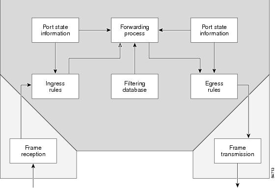
The relaying function level, as displayed in Figure 2, is the lowest level in the architectural model described in the IEEE 802.1Q standard and presents three types of rules:
•
•
•
Figure 2 Relaying Function
The Tagging Scheme
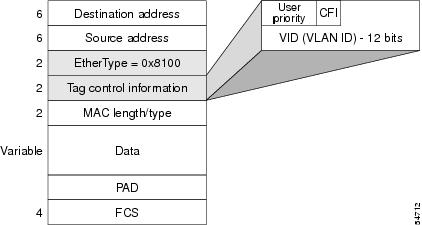
Figure 3 shows the tagging scheme proposed by the 802.3ac standard, that is, the addition of the four octets after the source MAC address. Their presence is indicated by a particular value of the EtherType field (called TPID), which has been fixed to be equal to 0x8100. When a frame has the EtherType equal to 0x8100, this frame carries the tag IEEE 802.1Q/802.1p. The tag is stored in the following two octets and it contains 3 bits of user priority, 1 bit of Canonical Format Identifier (CFI), and 12 bits of VLAN ID (VID). The 3 bits of user priority are used by the 802.1p standard; the CFI is used for compatibility reasons between Ethernet-type networks and Token Ring-type networks. The VID is the identification of the VLAN, which is basically used by the 802.1Q standard; being on 12 bits, it allows the identification of 4096 VLANs.
After the two octets of TPID and the two octets of the Tag Control Information field there are two octets that originally would have been located after the Source Address field where there is the TPID. They contain either the MAC length in the case of IEEE 802.3 or the EtherType in the case of Ethernet version 2.
Figure 3 Tagging Scheme
The EtherType and VLAN ID are inserted after the MAC source address, but before the original Ethertype/Length or Logical Link Control (LLC). The 1-bit CFI included a T-R Encapsulation bit so that Token Ring frames can be carried across Ethernet backbones without using 802.1H translation.
Adding a Tag Recomputes the Frame Control Sequence
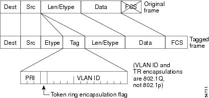
Figure 4 shows how adding a tag in a frame recomputes the Frame Control Sequence. 802.1p and 802.1Q share the same tag.
Figure 4 Adding a Tag Recomputes the Frame Control Sequence
Native VLAN
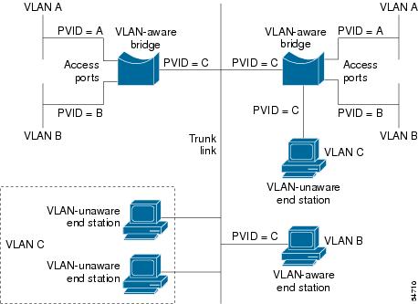
Each physical port has a parameter called PVID. Every 802.1Q port is assigned a PVID value that is of its native VLAN ID (default is VLAN 1). All untagged frames are assigned to the LAN specified in the PVID parameter. When a tagged frame is received by a port, the tag is respected. If the frame is untagged, the value contained in the PVID is considered as a tag. Because the frame is untagged and the PVID is tagged to allow the coexistence, as shown in Figure 5, on the same pieces of cable of VLAN-aware bridge/stations and of VLAN-unaware bridges/stations. Consider, for example, the two stations connected to the central trunk link in the lower part of Figure 5. They are VLAN-unaware and they will be associated to the VLAN C, because the PVIDs of the VLAN-aware bridges are equal to VLAN C. Because the VLAN-unaware stations will send only untagged frames, when the VLAN-aware bridge devices receive these untagged frames they will assign them to VLAN C.
Figure 5 Native VLAN
PVST+
PVST+ provides support for 802.1Q trunks and the mapping of multiple spanning trees to the single spanning tree of 802.1Q switches.
The PVST+ architecture distinguishes three types of regions:
•
•
•
Each region consists of a homogenous type of switch. A PVST region can be connected to a PVST+ region by connecting two ISL ports. Similarly, a PVST+ region can be connected to an MST region by connecting two 802.1Q ports.
At the boundary between a PVST region and a PVST+ region the mapping of spanning trees is one-to-one. At the boundary between a MST region and a PVST+ region, the ST in the MST region maps to one PVST in the PVST+ region. The one it maps to is called the common spanning tree (CST). The default CST is the PVST of VLAN 1 (Native VLAN).
All PVSTs, except for the CST, are tunneled through the MST region. Tunneling means that bridge protocol data units (BPDUs) are flooded through the MST region along the single spanning tree present in the MST region.
Note
Ingress and Egress Rules
The BPDU transmission on the 802.1Q port of a PVST+ router will be implemented in compliance with the following rules:
•
•
•
•
•
•
The BPDU reception on the 802.1Q port of a PVST+ router will follow these rules:
•
•
•
•
•
•
Integrated Routing and Bridging
IRB enables a user to route a given protocol between routed interfaces and bridge groups or route a given protocol between the bridge groups. Integrated routing and bridging is supported on the following protocols:
•
•
•
VLAN Colors
VLAN switching is accomplished through frame tagging where traffic originating and contained within a particular virtual topology carries a unique VLAN ID as it traverses a common backbone or trunk link. The VLAN ID enables VLAN switching devices to make intelligent forwarding decisions based on the embedded VLAN ID. Each VLAN is differentiated by a color, or VLAN identifier. The unique VLAN ID determines the frame coloring for the VLAN. Packets originating and contained within a particular VLAN carry the identifier that uniquely defines that VLAN (by the VLAN ID).
The VLAN ID allows VLAN switches and routers to selectively forward packets to ports with the same VLAN ID. The switch that receives the frame from the source station inserts the VLAN ID and the packet is switched onto the shared backbone network. When the frame exits the switched LAN, a switch strips the header and forwards the frame to interfaces that match the VLAN color. If you are using a Cisco network management product such as VlanDirector, you can actually color code the VLANs and monitor VLAN graphically.
Why Implement VLANs?
Network managers can logically group networks that span all major topologies, including high-speed technologies such as, ATM, FDDI, and Fast Ethernet. By creating virtual LANs, system and network administrators can control traffic patterns and react quickly to relocations and keep up with constant changes in the network due to moving requirements and node relocation just by changing the VLAN member list in the router configuration. They can add, remove, or move devices or make other changes to network configuration using software to make the changes.
Issues regarding benefits of creating VLANs should have been addressed when you developed your network design. Issues to consider include the following:
•
•
•
•
Communicating Between VLANs
Cisco IOS software provides full-feature routing at Layer 3 and translation at Layer 2 between VLANs. Five different protocols are available for routing between VLANs:
•
All five of these technologies are based on OSI Layer 2 bridge multiplexing mechanisms.
Inter-Switch Link Protocol
The Inter-Switch Link (ISL) protocol is used to interconnect two VLAN-capable Ethernet, Fast Ethernet, or Gigabit Ethernet devices, such as the Catalyst 3000 or 5000 switches and Cisco 7500 routers. The ISL protocol is a packet-tagging protocol that contains a standard Ethernet frame and the VLAN information associated with that frame. The packets on the ISL link contain a standard Ethernet, FDDI, or Token Ring frame and the VLAN information associated with that frame. ISL is currently supported only over Fast Ethernet links, but a single ISL link, or trunk, can carry different protocols from multiple VLANs.
For the procedures for configuring ISL and Token Ring ISL (TRISL) features, see the "Configuring Routing Between VLANs with Inter-Switch Link Encapsulation" module.
IEEE 802.10 Protocol
The IEEE 802.10 protocol provides connectivity between VLANs. Originally developed to address the growing need for security within shared LAN/MAN environments, it incorporates authentication and encryption techniques to ensure data confidentiality and integrity throughout the network. Additionally, by functioning at Layer 2, it is well suited to high-throughput, low-latency switching environments. The IEEE 802.10 protocol can run over any LAN or HDLC serial interface.
For the procedures for configuring routing between VLANs with IEEE 802.10 encapsulation, see the "Configuring Routing Between VLANs with IEEE 802.10 Encapsulation" module.
IEEE 802.1Q Protocol
The IEEE 802.1Q protocol is used to interconnect multiple switches and routers, and for defining VLAN topologies. Cisco currently supports IEEE 802.1Q for Fast Ethernet and Gigabit Ethernet interfaces.
Note
For the procedures for configuring routing between VLANs with IEEE 802.1Q encapsulation, see the "Configuring Routing Between VLANs with IEEE 802.1Q Encapsulation" module.
ATM LANE Protocol
The ATM LAN Emulation (LANE) protocol provides a way for legacy LAN users to take advantage of ATM benefits without requiring modifications to end-station hardware or software. LANE emulates a broadcast environment like IEEE 802.3 Ethernet on top of an ATM network that is a point-to-point environment.
LANE makes ATM function like a LAN. LANE allows standard LAN drivers like NDIS and ODI to be used. The virtual LAN is transparent to applications. Applications can use normal LAN functions without the underlying complexities of the ATM implementation. For example, a station can send broadcasts and multicasts, even though ATM is defined as a point-to-point technology and does not support any-to-any services.
To accomplish this, special low-level software is implemented on an ATM client workstation, called the LAN Emulation Client (LEC). The client software communicates with a central control point called a LAN Emulation Server (LES). A broadcast and unknown server (BUS) acts as a central point to distribute broadcasts and multicasts. The LAN Emulation Configuration Server (LECS) holds a database of LECs and the ELANs they belong to. The database is maintained by a network administrator.
These protocols are described in the Internetwork Design Guide.
ATM LANE Fast Simple Server Replication Protocol
To improve the ATM LANE Simple Server Replication Protocol (SSRP), Cisco introduced the ATM LANE Fast Simple Server Replication Protocol (FSSRP). FSSRP differs from LANE SSRP in that all configured LANE servers of an ELAN are always active. FSSRP-enabled LANE clients have virtual circuits (VCs) established to a maximum of four LANE servers and BUSs at one time. If a single LANE server goes down, the LANE client quickly switches over to the next LANE server and BUS, resulting in no data or LE ARP table entry loss and no extraneous signalling.
The FSSRP feature improves upon SSRP such that LANE server and BUS switchover for LANE clients is immediate. With SSRP, a LANE server would go down, and depending on the network load, it may have taken considerable time for the LANE client to come back up joined to the correct LANE server and BUS. In addition to going down with SSRP, the LANE client would do the following:
•
•
•
FSSRP was designed to alleviate these problems with the LANE client. With FSSRP, each LANE client is simultaneously joined to up to four LANE servers and BUSs. The concept of the master LANE server and BUS is maintained; the LANE client uses the master LANE server when it needs LANE server BUS services. However, the difference between SSRP and FSSRP is that if and when the master LANE server goes down, the LANE client is already connected to multiple backup LANE servers and BUSs. The LANE client simply uses the next backup LANE server and BUS as the master LANE server and BUS.
VLAN Interoperability
Cisco IOS features bring added benefits to the VLAN technology. Enhancements to ISL, IEEE 802.10, and ATM LANE implementations enable routing of all major protocols between VLANs. These enhancements allow users to create more robust networks incorporating VLAN configurations by providing communications capabilities between VLANs.
Inter-VLAN Communications
The Cisco IOS supports full routing of several protocols over ISL and ATM LANE VLANs. IP, Novell IPX, and AppleTalk routing are supported over IEEE 802.10 VLANs. Standard routing attributes such as network advertisements, secondaries, and help addresses are applicable, and VLAN routing is fast switched. Table 1 shows protocols supported for each VLAN encapsulation format and corresponding Cisco IOS software releases in which each protocol was first supported.
VLAN Translation
VLAN translation refers to the ability of the Cisco IOS software to translate between different VLANs or between VLAN and non-VLAN encapsulating interfaces at Layer 2. Translation is typically used for selective inter-VLAN switching of nonroutable protocols and to extend a single VLAN topology across hybrid switching environments. It is also possible to bridge VLANs on the main interface; the VLAN encapsulating header is preserved. Topology changes in one VLAN domain do not affect a different VLAN.
Designing Switched VLANs
By the time you are ready to configure routing between VLANs, you will have already defined them through the switches in your network. Issues related to network design and VLAN definition should be addressed during your network design. See the Internetwork Design Guide and appropriate switch documentation for information on these topics:
•
•
•
•
•
•