Feedback
Table Of Contents
IEEE 802.1Q-in-Q VLAN Tag Termination
Prerequisites for IEEE 802.1Q-in-Q VLAN Tag Termination
Restrictions for IEEE 802.1Q-in-Q VLAN Tag Termination
Information About IEEE 802.1Q-in-Q VLAN Tag Termination
IEEE 802.1Q-in-Q VLAN Tag Termination on Subinterfaces
Cisco 10000 Series Router Application
Security ACL Application on the Cisco 10000 Router
Unambiguous and Ambiguous Subinterfaces
How to Configure IEEE 802.1Q-in-Q VLAN Tag Termination
Configuring the Interfaces for IEEE 802.1Q-in-Q VLAN Tag Termination
Verifying the IEEE 802.1Q-in-Q VLAN Tag Termination
Configuration Examples for IEEE 802.1Q-in-Q VLAN Tag Termination
Configuring any Keyword on Subinterfaces for IEEE 802.1Q-in-Q VLAN Tag Termination: Example
IEEE 802.1Q-in-Q VLAN Tag Termination
Encapsulating IEEE 802.1Q VLAN tags within 802.1Q enables service providers to use a single VLAN to support customers who have multiple VLANs. The IEEE 802.1Q-in-Q VLAN Tag Termination feature on the subinterface level preserves VLAN IDs and keeps traffic in different customer VLANs segregated.
Feature History for the IEEE 802.1Q-in-Q VLAN Tag Termination Feature
12.3(7)T
This feature was introduced.
12.3(7)XI1
This feature was implemented on the Cisco 10000 series router.
Finding Support Information for Platforms and Cisco IOS Software Images
Use Cisco Feature Navigator to find information about platform support and Cisco IOS software image support. Access Cisco Feature Navigator at http://www.cisco.com/go/fn. You must have an account on Cisco.com. If you do not have an account or have forgotten your username or password, click Cancel at the login dialog box and follow the instructions that appear.
Contents
•
Prerequisites for IEEE 802.1Q-in-Q VLAN Tag Termination, page 2
•
•
•
•
•
Prerequisites for IEEE 802.1Q-in-Q VLAN Tag Termination
•
•
Restrictions for IEEE 802.1Q-in-Q VLAN Tag Termination
The following restrictions apply to the Cisco 10000 series router:
•
•
•
•
•
Information About IEEE 802.1Q-in-Q VLAN Tag Termination
This section lists the concepts that the user should understand in order to perform the tasks in the "How to Configure IEEE 802.1Q-in-Q VLAN Tag Termination" section on page 6. The following concepts are described in this section:
•
•
•
IEEE 802.1Q-in-Q VLAN Tag Termination on Subinterfaces
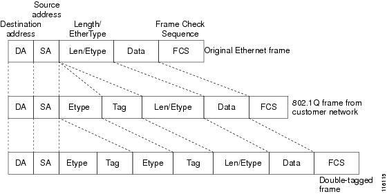
IEEE 802.1Q-in-Q VLAN Tag Termination simply adds another layer of IEEE 802.1Q tag (called "metro tag" or "PE-VLAN") to the 802.1Q tagged packets that enter the network. The purpose is to expand the VLAN space by tagging the tagged packets, thus producing a "double-tagged" frame. The expanded VLAN space allows the service provider to provide certain services, such as Internet access on specific VLANs for specific customers, and yet still allows the service provider to provide other types of services for their other customers on other VLANs.
Generally the service provider's customers require a range of VLANs to handle multiple applications. Service providers can allow their customers to use this feature to safely assign their own VLAN IDs on subinterfaces because these subinterface VLAN IDs are encapsulated within a service-provider designated VLAN ID for that customer. Therefore there is no overlap of VLAN IDs among customers, nor does traffic from different customers become mixed. The double-tagged frame is "terminated" or assigned on a subinterface with an expanded encapsulation dot1q command that specifies the two VLAN ID tags (outer VLAN ID and inner VLAN ID) terminated on the subinterface. See Figure 1 on page 3.
IEEE 802.1Q-in-Q VLAN Tag Termination is generally supported on whichever Cisco IOS features or protocols are supported on the subinterface; the exception is that Cisco 10000 series router only supports PPPoE. For example if you can run PPPoE on the subinterface, you can configure a double-tagged frame for PPPoE. The only restriction is whether you assign ambiguous or unambiguous subinterfaces for the inner VLAN ID. See the "Unambiguous and Ambiguous Subinterfaces" section on page 5.
Note
The primary benefit for the service provider is reduced number of VLANs supported for the same number of customers. Other benefits of this feature include:
•
•
The Q-in-Q VLAN tag termination feature is simpler than the IEEE 802.1Q tunneling feature deployed for the Catalyst 6500 series switches or the Catalyst 3550 and Catalyst 3750 switches. Whereas switches require IEEE 802.1Q tunnels on interfaces to carry double-tagged traffic, routers need only encapsulate Q-in-Q VLAN tags within another level of 802.1Q tags in order for the packets to arrive at the correct destination.
Figure 1 Untagged, 802.1Q-Tagged, and Double-Tagged Ethernet Frames
Cisco 10000 Series Router Application
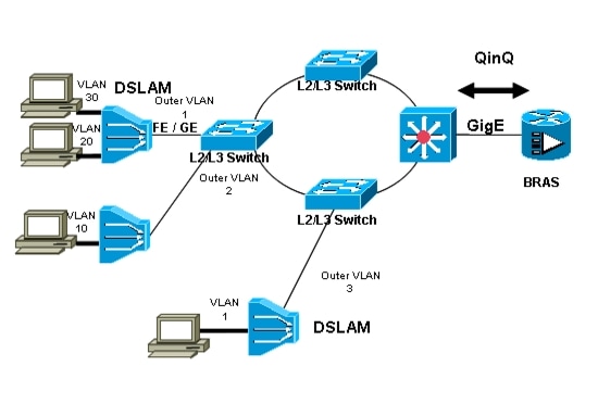
For the emerging broadband Ethernet-based DSLAM market, the Cisco 10000 router supports Q-in-Q encapsulation. With the Ethernet-based DSLAM model shown in Figure 2, customers typically get their own VLAN and all these VLANs are aggregated on a DSLAM.
Figure 2
Broadband Ethernet-based DSLAM Model of Q-in-Q VLANs
VLAN aggregation on a DSLAM will result in a lot of aggregate VLANs that at some point need to be terminated on the broadband remote access servers (BRAS). Although the model could connect the DSLAMs directly to the BRAS, a more common model uses the existing Ethernet-switched network where each DSLAM VLAN ID is tagged with a second tag (Q-in-Q) as it connects into the Ethernet-switched network.
The only model that is supported is PPPoE over Q-in-Q (PPPoEoQinQ). This can either be a PPP terminated session or as a L2TP LAC session. No IP over Q-in-Q is supported.
The Cisco 10000 series router already supports plain PPPoE and PPP over 802.1Q encapsulation. Supporting PPP over Q-in-Q encapsulation is new. PPP over Q-in-Q encapsulation processing is an extension to 802.1q encapsulation processing. A Q-in-Q frame looks like a VLAN 802.1Q frame, only it has two 802.1Q tags instead of one. See Figure 1.
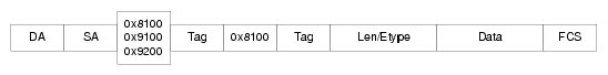
PPP over Q-in-Q encapsulation supports configurable outer tag Ethertype. The configurable Ethertype field values are 0x8100 (default), 0x9100, and 0x9200. See Figure 3.
Figure 3
Supported Configurable Ethertype Field Values
Security ACL Application on the Cisco 10000 Router
The IEEE 802.1Q-in-Q VLAN Tag Termination feature provides limited security access control list (ACL) support for the Cisco 10000 series router.
If you apply an ACL to PPPoE traffic on a Q-in-Q subinterface in a VLAN, apply the ACL directly on the PPPoE session, using virtual access interfaces (VAIs) or RADIUS attribute 11 or 242.
You can apply ACLs to virtual access interfaces by configuring them under virtual template interfaces. You can also configure ACLs by using RADIUS attribute 11 or 242. When you use attribute 242, a maximum of 30,000 sessions can have ACLs.
ACLs that are applied to the VLAN Q-in-Q subinterface have no effect and are silently ignored. In the following example, ACL 1 that is applied to the VLAN Q-in-Q subinterface level will be ignored:
Router(config)# interface FastEthernet3/0/0.100Router(config-subif)# encapsulation dot1q 100 second-dot1q 200Router(config-subif)# ip access-group 1Unambiguous and Ambiguous Subinterfaces
The encapsulation dot1q command is used to configure Q-in-Q termination on a subinterface. The command accepts an Outer VLAN ID and one or more Inner VLAN IDs. The outer VLAN ID always has a specific value, while inner VLAN ID can either be a specific value or a range of values.
A subinterface that is configured with a single Inner VLAN ID is called an unambiguous Q-in-Q subinterface. In the following example, Q-in-Q traffic with an Outer VLAN ID of 101 and an Inner VLAN ID of 1001 is mapped to the Gigabit Ethernet 1/0.100 subinterface:
Router(config)# interface gigabitEehernet1/0.100Router(config-subif)# encapsulation dot1q 101 second-dot1q 1001A subinterface that is configured with multiple Inner VLAN IDs is called an ambiguous Q-in-Q subinterface. By allowing multiple Inner VLAN IDs to be grouped together, ambiguous Q-in-Q subinterfaces allow for a smaller configuration, improved memory usage and better scalability.
In the following example, Q-in-Q traffic with an Outer VLAN ID of 101 and Inner VLAN IDs anywhere in the 2001-2100 and 3001-3100 range is mapped to the Gigabit Ethernet 1/0.101 subinterface.:
Router(config)# interface gigabitethernet1/0.101Router(config-subif)# encapsulation dot1q 101 second-dot1q 2001-2100,3001-3100Ambiguous subinterfaces can also use the any keyword to specify the inner VLAN ID.
See the "Configuration Examples for IEEE 802.1Q-in-Q VLAN Tag Termination" section on page 11 for an example of how VLAN IDs are assigned to subinterfaces, and for a detailed example of how the any keyword is used on ambiguous subinterfaces.
Only PPPoE is supported on ambiguous subinterfaces. Standard IP routing is not supported on ambiguous subinterfaces.
Note
How to Configure IEEE 802.1Q-in-Q VLAN Tag Termination
This section contains the following tasks:
•
•
Configuring the Interfaces for IEEE 802.1Q-in-Q VLAN Tag Termination
Perform this task to configure the main interface used for the Q-in-Q double tagging and to configure the subinterfaces. An optional step in this task shows you how to configure the EtherType field to be 0x9100 for the outer VLAN tag, if that is required. After the subinterface is defined, the 802.1Q encapsulation is configured to use the double tagging.
Prerequisites
For the Cisco 10000 series router:
•
•
SUMMARY STEPS
Steps to configure EtherType field for outer VLAN tag (Optional):
1.
2.
3.
4.
Steps to configure the Q-in-Q Subinterface (Required):
5.
6.
7.
8.
9.
10.
11.
DETAILED STEPS
Verifying the IEEE 802.1Q-in-Q VLAN Tag Termination
Perform this optional task to verify the configuration of the IEEE 802.1Q-in-Q VLAN Tag Termination feature.
SUMMARY STEPS
1.
2.
3.
DETAILED STEPS
Step 1
Enables privileged EXEC mode. Enter your password if prompted.
Router> enableStep 2
Use this command to show the currently running configuration on the device. You can use delimiting characters to display only the relevant parts of the configuration.
The following shows the currently running configuration on a Cisco 7300 series router:
Router# show running-config...interface FastEthernet0/0.201encapsulation dot1Q 201ip address 10.7.7.5 255.255.255.252!interface FastEthernet0/0.401encapsulation dot1Q 401ip address 10.7.7.13 255.255.255.252!interface FastEthernet0/0.201999encapsulation dot1Q 201 second-dot1q anypppoe enable!interface FastEthernet0/0.2012001encapsulation dot1Q 201 second-dot1q 2001ip address 10.8.8.9 255.255.255.252!interface FastEthernet0/0.2012002encapsulation dot1Q 201 second-dot1q 2002ip address 10.8.8.13 255.255.255.252!interface FastEthernet0/0.4019999encapsulation dot1Q 401 second-dot1q 100-900,1001-2000pppoe enable!interface GigabitEthernet5/0.101encapsulation dot1Q 101ip address 10.7.7.1 255.255.255.252!interface GigabitEthernet5/0.301encapsulation dot1Q 301ip address 10.7.7.9 255.255.255.252!interface GigabitEthernet5/0.301999encapsulation dot1Q 301 second-dot1q anypppoe enable!interface GigabitEthernet5/0.1011001encapsulation dot1Q 101 second-dot1q 1001ip address 10.8.8.1 255.255.255.252!interface GigabitEthernet5/0.1011002encapsulation dot1Q 101 second-dot1q 1002ip address 10.8.8.5 255.255.255.252!interface GigabitEthernet5/0.1019999encapsulation dot1Q 101 second-dot1q 1-1000,1003-2000pppoe enable...The following shows the currently running configuration on a Cisco 10000 series router:
Router# show running-config...interface FastEthernet1/0/0.201encapsulation dot1Q 201ip address 10.7.7.5 255.255.255.252!interface FastEthernet1/0/0.401encapsulation dot1Q 401ip address 10.7.7.13 255.255.255.252!interface FastEthernet1/0/0.201999encapsulation dot1Q 201 second-dot1q anypppoe enable!interface FastEthernet1/0/0.4019999encapsulation dot1Q 401 second-dot1q 100-900,1001-2000pppoe enable!interface GigabitEthernet5/0/0.101encapsulation dot1Q 101ip address 10.7.7.1 255.255.255.252!interface GigabitEthernet5/0/0.301encapsulation dot1Q 301ip address 10.7.7.9 255.255.255.252!interface GigabitEthernet5/0/0.301999encapsulation dot1Q 301 second-dot1q anypppoe enable!interface GigabitEthernet5/0/0.1019999encapsulation dot1Q 101 second-dot1q 1-1000,1003-2000pppoe enable...Step 3
Use this command to show the statistics for all the 802.1Q VLAN IDs. In this example, only the outer VLAN ID is displayed.
Note
Router# show vlans dot1qTotal statistics for 802.1Q VLAN 1:441 packets, 85825 bytes input1028 packets, 69082 bytes outputTotal statistics for 802.1Q VLAN 101:5173 packets, 510384 bytes input3042 packets, 369567 bytes outputTotal statistics for 802.1Q VLAN 201:1012 packets, 119254 bytes input1018 packets, 120393 bytes outputTotal statistics for 802.1Q VLAN 301:3163 packets, 265272 bytes input1011 packets, 120750 bytes outputTotal statistics for 802.1Q VLAN 401:1012 packets, 119254 bytes input1010 packets, 119108 bytes output
Configuration Examples for IEEE 802.1Q-in-Q VLAN Tag Termination
This section contains the following example:
•
Configuring any Keyword on Subinterfaces for IEEE 802.1Q-in-Q VLAN Tag Termination: Example
Some ambiguous subinterfaces can use the any keyword for the inner VLAN ID specification. The any keyword represents any inner VLAN ID that is not explicitly configured on any other interface. In the following example, seven subinterfaces are configured with various outer and inner VLAN IDs.
Note
interface GigabitEthernet1/0/0.1encapsulation dot1q 100 second-dot1q 100interface GigabitEthernet1/0/0.2encapsulation dot1q 100 second-dot1q 200interface GigabitEthernet1/0/0.3encapsulation dot1q 100 second-dot1q 300-400,500-600interface GigabitEthernet1/0/0.4encapsulation dot1q 100 second-dot1q anyinterface GigabitEthernet1/0/0.5encapsulation dot1q 200 second-dot1q 50interface GigabitEthernet1/0/0.6encapsulation dot1q 200 second-dot1q 1000-2000,3000-4000interface GigabitEthernet1/0/0.7encapsulation dot1q 200 second-dot1q anyTable 1 shows which subinterfaces are mapped to different values of the outer and inner VLAN ID on Q-in-Q frames that come in on Gigabit Ethernet interface 1/0/0.
A new subinterface is now configured:
interface GigabitEthernet1/0/0.8encapsulation dot1q 200 second-dot1q 200-600,900-999Table 2 shows the changes made to the table for the outer VLAN ID of 200. Notice that subinterface 1/0/0.7 configured with the any keyword now has new inner VLAN ID mappings.
Additional References
The following sections provide references related to the IEEE 802.1Q-in-Q VLAN Tag Termination feature.
Related Documents
Interface commands: complete command syntax, command mode, defaults, usage guidelines, and examples
Cisco IOS Interface and Hardware Component Command Reference, Release 12.3 T
Interface configuration examples
Cisco IOS Interface and Hardware Component Configuration Guide
Standards
MIBs
RFCs
No new or modified RFCs are supported by this feature, and support for existing RFCs has not been modified by this feature.
—
Technical Assistance
Command Reference
The following commands are pertinent to this feature. To see the command pages for these commands and other commands used with this feature, go to the Cisco IOS Master Commands List, Release 12.4, at http://www.cisco.com/univercd/cc/td/doc/product/software/ios124/124mindx/
124index.htm.•
•
•
CCDE, CCENT, Cisco Eos, Cisco Lumin, Cisco Nexus, Cisco StadiumVision, Cisco TelePresence, Cisco WebEx, the Cisco logo, DCE, and Welcome to the Human Network are trademarks; Changing the Way We Work, Live, Play, and Learn and Cisco Store are service marks; and Access Registrar, Aironet, AsyncOS, Bringing the Meeting To You, Catalyst, CCDA, CCDP, CCIE, CCIP, CCNA, CCNP, CCSP, CCVP, Cisco, the Cisco Certified Internetwork Expert logo, Cisco IOS, Cisco Press, Cisco Systems, Cisco Systems Capital, the Cisco Systems logo, Cisco Unity, Collaboration Without Limitation, EtherFast, EtherSwitch, Event Center, Fast Step, Follow Me Browsing, FormShare, GigaDrive, HomeLink, Internet Quotient, IOS, iPhone, iQuick Study, IronPort, the IronPort logo, LightStream, Linksys, MediaTone, MeetingPlace, MeetingPlace Chime Sound, MGX, Networkers, Networking Academy, Network Registrar, PCNow, PIX, PowerPanels, ProConnect, ScriptShare, SenderBase, SMARTnet, Spectrum Expert, StackWise, The Fastest Way to Increase Your Internet Quotient, TransPath, WebEx, and the WebEx logo are registered trademarks of Cisco Systems, Inc. and/or its affiliates in the United States and certain other countries.
All other trademarks mentioned in this document or website are the property of their respective owners. The use of the word partner does not imply a partnership relationship between Cisco and any other company. (0809R)
Any Internet Protocol (IP) addresses used in this document are not intended to be actual addresses. Any examples, command display output, and figures included in the document are shown for illustrative purposes only. Any use of actual IP addresses in illustrative content is unintentional and coincidental.
© 2008 Cisco Systems, Inc. All rights reserved.