Feedback
Table Of Contents
Tunneling to Connect Non-IP Multicast Areas
Prerequisites for Tunneling to Connect Non-IP Multicast Areas
Information About Tunneling to Connect Non-IP Multicast Areas
Benefits of Tunneling to Connect Non-IP Multicast Areas
IP Multicast Static Route (mroute)
How to Connect Non-IP Multicast Areas
Configuring a Tunnel to Connect Non-IP Multicast Areas
Configuration Examples for Tunneling to Connect Non-IP Multicast Areas
Tunneling to Connect Non-IP Multicast Areas: Example
Feature Information for Tunneling to Connect Non-IP Multicast Areas
Tunneling to Connect Non-IP Multicast Areas
This module describes how to configure a Generic Route Encapsulation (GRE) tunnel to tunnel IP multicast packets between non-IP multicast areas. The benefit is that IP multicast traffic can be sent from a source to a multicast group, over an area where IP multicast is not supported.
Module History
This module was first published on May 2, 2005, and last updated on May 2, 2005.
Finding Feature Information in This Document
Not all features may be supported in your Cisco IOS software release. Use the "Feature Information for Tunneling to Connect Non-IP Multicast Areas" to find information about feature support and configuration.
Contents
•
Prerequisites for Tunneling to Connect Non-IP Multicast Areas
•
•
•
•
Prerequisites for Tunneling to Connect Non-IP Multicast Areas
This module assumes you understand the concepts in the "IP Multicast Technology Overview" module.
Information About Tunneling to Connect Non-IP Multicast Areas
Before connecting non-IP multicast areas, you should understand the following concepts:
•
•
Benefits of Tunneling to Connect Non-IP Multicast Areas
•
•
IP Multicast Static Route (mroute)
IP multicast static routes (mroutes) allow you to have multicast paths diverge from the unicast paths. When using Protocol Independent Multicast (PIM), the router expects to receive packets on the same interface where it sends unicast packets back to the source. This expectation is beneficial if your multicast and unicast topologies are congruent. However, you might want unicast packets to take one path and multicast packets to take another.
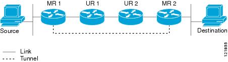
The most common reason for using separate unicast and multicast paths is tunneling. When a path between a source and a destination does not support multicast routing, a solution is to configure two routers with a GRE tunnel between them. In Figure 1, each unicast router (UR) supports unicast packets only; each multicast router (MR) supports multicast packets.
Figure 1 Tunnel for Multicast Packets
In Figure 1, Source delivers multicast packets to Destination by using MR 1 and MR 2. MR 2 accepts the multicast packet only if it believes it can reach Source over the tunnel. If this situation is true, when Destination sends unicast packets to Source, MR 2 sends them over the tunnel. The check that MR2 can reach Source over the tunnel is a Reverse Path Forwarding (RPF) check, and the static mroute allows the check to be successful when the interface that the multicast packet arrives on is not the unicast path back to the source. Sending the packet over the tunnel could be slower than natively sending it through UR 2, UR 1, and MR 1.
A multicast static route allows you to use the configuration in Figure 1 by configuring a static multicast source. The system uses the configuration information instead of the unicast routing table to route the traffic. Therefore, multicast packets can use the tunnel without having unicast packets use the tunnel. Static mroutes are local to the router they are configured on and not advertised or redistributed in any way to any other router.
How to Connect Non-IP Multicast Areas
This section contains the following procedure:
•
Configuring a Tunnel to Connect Non-IP Multicast Areas
Configure a multicast static route if you want your multicast paths to differ from your unicast paths. For example, you might have a tunnel between two routers because the unicast path between a source and destination does not support multicast routing.
SUMMARY STEPS
1.
2.
3.
4.
5.
6.
7.
8.
9.
10.
11.
12.
13.
14.
DETAILED STEPS
Configuration Examples for Tunneling to Connect Non-IP Multicast Areas
This section provides the following configuration example:
•
Tunneling to Connect Non-IP Multicast Areas: Example
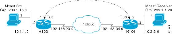
In Figure 2, the multicast source (10.1.1.1) is connected to R102 and is configured for multicast group 239.1.1.20. The multicast receiver (10.2.2.3) is connected to R104 and is configured to receive multicast packets for group 239.1.1.20. Separating R102 and R104 is an IP cloud, which is not configured for multicast routing.
Figure 2 Tunnel Connecting Non-IP Multicast Areas
A tunnel is configured between R102 to R104 sourced with their loopback interfaces. The ip pim sparse-dense-mode command is configured on tunnel interfaces and multicast-routing is enabled on R102 and R104. Sparse-dense mode configuration on the tunnel interfaces allows sparse-mode or dense-mode packets to be forwarded over the tunnel depending on rendezvous point (RP) configuration for the group.
Note
Note
•
Assuming R102 to be the RP (RP address 2.2.2.2) in this case, the mroute would be the ip mroute 2.2.2.2 255.255.255.255 tunnel 0 command, which ensures a successful RPF check for traffic flowing over the shared tree.
•
In this case, when SPT traffic is flowing over tunnel interface an ip mroute 10.1.1.0 255.255.255.0 tunnel 0 command is configured on R104 to ensure a successful RPF verification for incoming (10.1.1.1, 239.1.1.20) multicast packets over the Tunnel 0 interface.
R102#
version 12.2hostname r102ip subnet-zerono ip domain-lookup!--- It stops IP domain lookup, which improves the show command response time.!ip multicast-routing!--- Enables IP multicast routing.!interface Loopback0ip address 2.2.2.2 255.255.255.255!--- Tunnel Source interface.!interface Tunnel0!--- Tunnel interface configured for PIM and carrying multicast packets to R104.ip address 192.168.24.1 255.255.255.252ip pim sparse-dense-modetunnel source Loopback0tunnel destination 4.4.4.4!interface Ethernet0/0!--- Interface connected to Source.ip address 10.1.1.2 255.255.255.0ip pim sparse-dense-mode!interface Serial8/0ip address 192.168.23.1 255.255.255.252!--- Note IP PIM sparse-dense mode is not configured on Serial interface.!router ospf 1log-adjacency-changesnetwork 2.2.2.2 0.0.0.0 area 0network 10.1.1.0 0.0.0.255 area 0network 192.168.23.0 0.0.0.255 area 0!ip classlessip pim bidir-enable!line con 0line aux 0line vty 0 4login!endR104#
version 12.2!hostname r104!ip subnet-zerono ip domain-lookup!--- It stops IP domain lookup, which improves the show command response time.!ip multicast-routing!--- Enables IP multicast routing.!interface Loopback0ip address 4.4.4.4 255.255.255.255!--- Tunnel Source interface.!interface Tunnel0ip address 192.168.24.2 255.255.255.252!--- Tunnel interface configured for PIM and carrying multicast packets.ip pim sparse-dense-modetunnel source Loopback0tunnel destination 2.2.2.2!interface Ethernet0/0ip address 10.2.2.2 255.255.255.0ip pim sparse-dense-mode!interface Serial9/0ip address 192.168.34.1 255.255.255.252!--- Note IP PIM sparse-dense mode is not configured on Serial interface.!!router ospf 1log-adjacency-changesnetwork 4.4.4.4 0.0.0.0 area 0network 10.2.2.0 0.0.0.255 area 0network 192.168.34.0 0.0.0.255 area 0!ip classlessno ip http serverip pim bidir-enableip mroute 10.1.1.0 255.255.255.0 Tunnel0!--- This Mroute ensures a successful RPF check for packets flowing from the source.!--- 10.1.1.1 over Shared tree in case of Dense more and SPT in case of Sparse mode.!ip mroute 2.2.2.2 255.255.255.255 tunnel 0!--- This Mroute is required for RPF check when Sparse mode multicast traffic is!--- flowing from RP (assuming R102 with 2.2.2.2 as RP) towards receiver via tunnel!--- before the SPT switchover.line con 0line aux 0line vty 0 4login!endAdditional References
The following sections provide references related to tunneling to connect non-IP multicast areas.
Related Documents
IP multicast commands: complete command syntax, command mode, command history, defaults, usage guidelines, and examples
Standards
MIBs
None
To locate and download MIBs for selected platforms, Cisco IOS releases, and feature sets, use Cisco MIB Locator found at the following URL:
RFCs
Technical Assistance
Feature Information for Tunneling to Connect Non-IP Multicast Areas
Table 1 lists the features in this module and provides links to specific configuration information. Only features that were introduced or modified in Cisco IOS Releases 12.2(1) or later appear in the table.
Not all commands may be available in your Cisco IOS software release. For details on when support for specific commands was introduced, see the command reference documents.
Cisco IOS software images are specific to a Cisco IOS software release, a feature set, and a platform. Use Cisco Feature Navigator to find information about platform support and Cisco IOS software image support. Access Cisco Feature Navigator (http://www.cisco.com/go/fn). You must have an account on Cisco.com. If you do not have an account or have forgotten your username or password, click Cancel at the login dialog box and follow the instructions that appear.
Table 1 Feature Information for Tunneling to Connect Non-IP Multicast Areas\
Any Internet Protocol (IP) addresses used in this document are not intended to be actual addresses. Any examples, command display output, and figures included in the document are shown for illustrative purposes only. Any use of actual IP addresses in illustrative content is unintentional and coincidental.
© 2007 Cisco Systems, Inc. All rights reserved.