Feedback
Table Of Contents
IP Multicast Technology Overview
Information About IP Multicast Technology
Role of IP Multicast in Information Delivery
Multicast Group Transmission Scheme
IP Multicast Routing Protocols
Protocol Independent Multicast
Multicast Source Discovery Protocol
Multicast Distribution Source Tree (Shortest Path Tree)
Multicast Distribution Shared Tree
Guidelines for Choosing a PIM Mode
Feature Information for IP Multicast Technology Overview
IP Multicast Technology Overview
First Published: May 2, 2005Last Updated: December 10, 2009IP multicast is a bandwidth-conserving technology that reduces traffic by delivering a single stream of information simultaneously to potentially thousands of businesses and homes. Applications that take advantage of multicast include video conferencing, corporate communications, distance learning, and distribution of software, stock quotes, and news.
This module contains a technical overview of IP multicast. IP multicast is an efficient way to use network resources, especially for bandwidth-intensive services such as audio and video. Before beginning to configure IP multicast, it is important that you understand the information presented in this module.
Finding Feature Information
Your software release may not support all the features documented in this module. For the latest feature information and caveats, see the release notes for your platform and software release. To find information about the features documented in this module, and to see a list of the releases in which each feature is supported, see the "Feature Information for IP Multicast Technology Overview" section.
Use Cisco Feature Navigator to find information about platform support and Cisco IOS and Catalyst OS software image support. To access Cisco Feature Navigator, go to http://www.cisco.com/go/cfn. An account on Cisco.com is not required.
Contents
•
Information About IP Multicast Technology
•
•
Information About IP Multicast Technology
Before you configure IP multicast, you should understand the following concepts:
•
•
•
•
•
•
Role of IP Multicast in Information Delivery
IP multicast is a bandwidth-conserving technology that reduces traffic by delivering a single stream of information simultaneously to potentially thousands of businesses and homes. Applications that take advantage of multicast include video conferencing, corporate communications, distance learning, and distribution of software, stock quotes, and news.
IP multicast routing enables a host (source) to send packets to a group of hosts (receivers) anywhere within the IP network by using a special form of IP address called the IP multicast group address. The sending host inserts the multicast group address into the IP destination address field of the packet and IP multicast routers and multilayer switches forward incoming IP multicast packets out all interfaces that lead to the members of the multicast group. Any host, regardless of whether it is a member of a group, can send to a group. However, only the members of a group receive the message.
Multicast Group Transmission Scheme
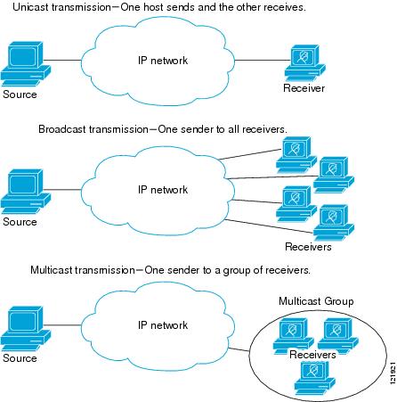
IP communication consists of hosts that act as senders and receivers of traffic as shown in Figure 1. Senders are called sources. Traditional IP communication is accomplished by a single host source sending packets to another single host (unicast transmission) or to all hosts (broadcast transmission). IP multicast provides a third scheme, allowing a host to send packets to a subset of all hosts (multicast transmission). This subset of receiving hosts is called a multicast group. The hosts that belong to a multicast group are called group members.
Multicast is based on this group concept. A multicast group is an arbitrary number of receivers that join a group in order to receive a particular data stream. This multicast group has no physical or geographical boundaries—the hosts can be located anywhere on the Internet or on any private internetwork. Hosts that are interested in receiving data from a source to a particular group must join that group. Joining a group is accomplished by a host receiver by way of the Internet Group Management Protocol (IGMP).
In a multicast environment, any host, regardless of whether it is a member of a group, can send to a group. However, only the members of a group can receive packets sent to that group. Multicast packets are delivered to a group using best-effort reliability, just like IP unicast packets.
Figure 1 IP Transmission Schemes
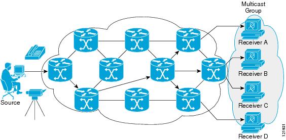
In Figure 2, the receivers (the designated multicast group) are interested in receiving the video data stream from the source. The receivers indicate their interest by sending an IGMP host report to the routers in the network. The routers are then responsible for delivering the data from the source to the receivers. The routers use Protocol Independent Multicast (PIM) (see the "Protocol Independent Multicast" section) to dynamically create a multicast distribution tree. The video data stream will then be delivered only to the network segments that are in the path between the source and the receivers.
Figure 2 Multicast Transmission
IP Multicast Routing Protocols
The Cisco IOS software supports the following protocols to implement IP multicast routing:
•
•
•
•
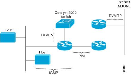
Figure 3 shows where these protocols operate within the IP multicast environment.
Figure 3 IP Multicast Routing Protocols
IP Multicast Group Addressing
A multicast group is identified by its multicast group address. Multicast packets are delivered to that multicast group address. Unlike unicast addresses that uniquely identify a single host, multicast IP addresses do not identify a particular host. To receive the data sent to a multicast address, a host must join the group that address identifies. The data is sent to the multicast address and received by all the hosts that have joined the group indicating that they wish to receive traffic sent to that group. The multicast group address is assigned to a group at the source. Network administrators who assign multicast group addresses must make sure the addresses conform to the multicast address range assignments reserved by the Internet Assigned Numbers Authority (IANA).
IP Class D Addresses
IP multicast addresses have been assigned to the IPv4 Class D address space by IANA. The high-order four bits of a Class D address are 1110. Therefore, host group addresses can be in the range 224.0.0.0 to 239.255.255.255. A multicast address is chosen at the source (sender) for the receivers in a multicast group.
Note
IP Multicast Address Scoping
The multicast address range is subdivided to provide predictable behavior for various address ranges and for address reuse within smaller domains. Table 1 is a summary of the multicast address ranges. A brief summary description of each range follows.
Table 1 Multicast Address Range Assignments
Reserved Link-Local Addresses
The IANA has reserved the range 224.0.0.0 to 224.0.0.255 for use by network protocols on a local network segment. Packets with an address in this range are local in scope and are not forwarded by IP routers. Packets with link local destination addresses are typically sent with a time-to-live (TTL) value of 1 and are not forwarded by a router.
Within this range, reserved link-local addresses provide network protocol functions for which they are reserved. Network protocols use these addresses for automatic router discovery and to communicate important routing information. For example, Open Shortest Path First (OSPF) uses the IP addresses 224.0.0.5 and 224.0.0.6 to exchange link-state information.
IANA assigns single multicast address requests for network protocols or network applications out of the 224.0.1.xxx address range. Multicast routers forward these multicast addresses.
Globally Scoped Addresses
Addresses in the range 224.0.1.0 to 238.255.255.255 are called globally scoped addresses. These addresses are used to send multicast data between organizations across the Internet. Some of these addresses have been reserved by IANA for use by multicast applications. For example, the IP address 224.0.1.1 is reserved for Network Time Protocol (NTP).
Source Specific Multicast Addresses
Addresses in the range 232.0.0.0/8 are reserved for Source Specific Multicast (SSM) by IANA. In Cisco IOS software, you can use the ip pim ssm command to configure SSM for arbitrary IP multicast addresses also. SSM is an extension of Protocol Independent Multicast (PIM) that allows for an efficient data delivery mechanism in one-to-many communications. SSM is described in the "IP Multicast Delivery Modes" section.
GLOP Addresses
GLOP addressing (as proposed by RFC 2770, GLOP Addressing in 233/8) proposes that the 233.0.0.0/8 range be reserved for statically defined addresses by organizations that already have an AS number reserved. This practice is called GLOP addressing. The AS number of the domain is embedded into the second and third octets of the 233.0.0.0/8 address range. For example, AS 62010 is written in hexadecimal format as F23A. Separating the two octets F2 and 3A results in 242 and 58 in decimal format. These values result in a subnet of 233.242.58.0/24 that would be globally reserved for AS 62010 to use.
Limited Scope Addresses
The range 239.0.0.0 to 239.255.255.255 is reserved as administratively or limited scoped addresses for use in private multicast domains. These addresses are constrained to a local group or organization. Companies, universities, and other organizations can use limited scope addresses to have local multicast applications that will not be forwarded outside their domain. Routers typically are configured with filters to prevent multicast traffic in this address range from flowing outside an autonomous system (AS) or any user-defined domain. Within an AS or domain, the limited scope address range can be further subdivided so that local multicast boundaries can be defined.
Note
Layer 2 Multicast Addresses
Historically, network interface cards (NICs) on a LAN segment could receive only packets destined for their burned-in MAC address or the broadcast MAC address. In IP multicast, several hosts need to be able to receive a single data stream with a common destination MAC address. Some means had to be devised so that multiple hosts could receive the same packet and still be able to differentiate between several multicast groups. One method to accomplish this is to map IP multicast Class D addresses directly to a MAC address. Using this method, NICs can receive packets destined to many different MAC address.
Cisco Group Management Protocol (CGMP) is used on routers connected to Catalyst switches to perform tasks similar to those performed by IGMP. CGMP is necessary for those Catalyst switches that cannot distinguish between IP multicast data packets and IGMP report messages, both of which are addressed to the same group address at the MAC level.
IP Multicast Delivery Modes
IP multicast delivery modes differ only for the receiver hosts, not for the source hosts. A source host sends IP multicast packets with its own IP address as the IP source address of the packet and a group address as the IP destination address of the packet.
Any Source Multicast
For the Any Source Multicast (ASM) delivery mode, an IP multicast receiver host can use any version of IGMP to join a multicast group. This group is notated as G in the routing table state notation. By joining this group, the receiver host is indicating that it wants to receive IP multicast traffic sent by any source to group G. The network will deliver IP multicast packets from any source host with the destination address G to all receiver hosts in the network that have joined group G.
ASM requires group address allocation within the network. At any given time, an ASM group should only be used by a single application. When two applications use the same ASM group simultaneously, receiver hosts of both applications will receive traffic from both application sources. This may result in unexpected excess traffic in the network. This situation may cause congestion of network links and malfunction of the application receiver hosts.
Source Specific Multicast
Source Specific Multicast (SSM) is a datagram delivery model that best supports one-to-many applications, also known as broadcast applications. SSM is a core network technology for the Cisco implementation of IP multicast targeted for audio and video broadcast application environments.
For the SSM delivery mode, an IP multicast receiver host must use IGMP Version 3 (IGMPv3) to subscribe to channel (S,G). By subscribing to this channel, the receiver host is indicating that it wants to receive IP multicast traffic sent by source host S to group G. The network will deliver IP multicast packets from source host S to group G to all hosts in the network that have subscribed to the channel (S, G).
SSM does not require group address allocation within the network, only within each source host. Different applications running on the same source host must use different SSM groups. Different applications running on different source hosts can arbitrarily reuse SSM group addresses without causing any excess traffic on the network.
Protocol Independent Multicast
The Protocol Independent Multicast (PIM) protocol maintains the current IP multicast service mode of receiver-initiated membership. PIM is not dependent on a specific unicast routing protocol; it is IP routing protocol independent and can leverage whichever unicast routing protocols are used to populate the unicast routing table, including Enhanced Interior Gateway Routing Protocol (EIGRP), Open Shortest Path First (OSPF), Border Gateway Protocol (BGP), and static routes. PIM uses unicast routing information to perform the multicast forwarding function.
Although PIM is called a multicast routing protocol, it actually uses the unicast routing table to perform the reverse path forwarding (RPF) check function instead of building up a completely independent multicast routing table. Unlike other routing protocols, PIM does not send and receive routing updates between routers.
PIM is defined in RFC 2362, Protocol-Independent Multicast-Sparse Mode (PIM-SM): Protocol Specification.
PIM can operate in dense mode or sparse mode. The router can handle both sparse groups and dense groups at the same time. The mode determines how the router populates its multicast routing table and how the router forwards multicast packets it receives from its directly connected LANs.
For information about PIM forwarding (interface) modes, see the following sections:
PIM Dense Mode
PIM dense mode (PIM-DM) uses a push model to flood multicast traffic to every corner of the network. This push model is a method for delivering data to the receivers without the receivers requesting the data. This method is efficient in certain deployments in which there are active receivers on every subnet in the network.
In dense mode, a router assumes that all other routers want to forward multicast packets for a group. If a router receives a multicast packet and has no directly connected members or PIM neighbors present, a prune message is sent back to the source. Subsequent multicast packets are not flooded to this router on this pruned branch. PIM builds source-based multicast distribution trees.
PIM-DM initially floods multicast traffic throughout the network. Routers that have no downstream neighbors prune back the unwanted traffic. This process repeats every 3 minutes.
Routers accumulate state information by receiving data streams through the flood and prune mechanism. These data streams contain the source and group information so that downstream routers can build up their multicast forwarding table. PIM-DM supports only source trees—that is, (S,G) entries—and cannot be used to build a shared distribution tree.
Note
PIM Sparse Mode
PIM sparse mode (PIM-SM) uses a pull model to deliver multicast traffic. Only network segments with active receivers that have explicitly requested the data will receive the traffic.
Unlike dense mode interfaces, sparse mode interfaces are added to the multicast routing table only when periodic Join messages are received from downstream routers, or when a directly connected member is on the interface. When forwarding from a LAN, sparse mode operation occurs if an RP is known for the group. If so, the packets are encapsulated and sent toward the RP. When no RP is known, the packet is flooded in a dense mode fashion. If the multicast traffic from a specific source is sufficient, the first hop router of the receiver may send Join messages toward the source to build a source-based distribution tree.
PIM-SM distributes information about active sources by forwarding data packets on the shared tree. Because PIM-SM uses shared trees (at least, initially), it requires the use of a rendezvous point (RP). The RP must be administratively configured in the network. See the "Rendezvous Points" section for more information.
In sparse mode, a router assumes that other routers do not want to forward multicast packets for a group, unless there is an explicit request for the traffic. When hosts join a multicast group, the directly connected routers send PIM Join messages toward the RP. The RP keeps track of multicast groups. Hosts that send multicast packets are registered with the RP by the first hop router of that host. The RP then sends Join messages toward the source. At this point, packets are forwarded on a shared distribution tree. If the multicast traffic from a specific source is sufficient, the first hop router of the host may send Join messages toward the source to build a source-based distribution tree.
Sources register with the RP and then data is forwarded down the shared tree to the receivers. The edge routers learn about a particular source when they receive data packets on the shared tree from that source through the RP. The edge router then sends PIM (S,G) Join messages toward that source. Each router along the reverse path compares the unicast routing metric of the RP address to the metric of the source address. If the metric for the source address is better, it will forward a PIM (S,G) Join message toward the source. If the metric for the RP is the same or better, then the PIM (S,G) Join message will be sent in the same direction as the RP. In this case, the shared tree and the source tree would be considered congruent.
If the shared tree is not an optimal path between the source and the receiver, the routers dynamically create a source tree and stop traffic from flowing down the shared tree. This behavior is the default behavior in Cisco IOS software. Network administrators can force traffic to stay on the shared tree by using the Cisco IOS ip pim spt-threshold infinity command.
PIM-SM scales well to a network of any size, including those with WAN links. The explicit join mechanism prevents unwanted traffic from flooding the WAN links.
Sparse-Dense Mode
If you configure either sparse mode or dense mode on an interface, then sparseness or denseness is applied to the interface as a whole. However, some environments might require PIM to run in a single region in sparse mode for some groups and in dense mode for other groups.
An alternative to enabling only dense mode or only sparse mode is to enable sparse-dense mode. In this case, the interface is treated as dense mode if the group is in dense mode; the interface is treated in sparse mode if the group is in sparse mode. You must have an RP if the interface is in sparse-dense mode and you want to treat the group as a sparse group.
If you configure sparse-dense mode, the idea of sparseness or denseness is applied to the groups for which the router is a member.
Another benefit of sparse-dense mode is that Auto-RP information can be distributed in a dense mode; yet, multicast groups for user groups can be used in a sparse mode manner. Therefore there is no need to configure a default RP at the leaf routers.
When an interface is treated in dense mode, it is populated in the outgoing interface list of a multicast routing table when either of the following conditions is true:
•
•
When an interface is treated in sparse mode, it is populated in the outgoing interface list of a multicast routing table when either of the following conditions is true:
•
•
Bidirectional PIM
Bidirectional PIM (bidir-PIM) is an enhancement of the PIM protocol that was designed for efficient many-to-many communications within an individual PIM domain. Multicast groups in bidirectional mode can scale to an arbitrary number of sources with only a minimal amount of additional overhead.
The shared trees that are created in PIM sparse mode are unidirectional. This means that a source tree must be created to bring the data stream to the RP (the root of the shared tree) and then it can be forwarded down the branches to the receivers. Source data cannot flow up the shared tree toward the RP—this would be considered a bidirectional shared tree.
In bidirectional mode, traffic is routed only along a bidirectional shared tree that is rooted at the RP for the group. In bidir-PIM, the IP address of the RP acts as the key to having all routers establish a loop-free spanning tree topology rooted in that IP address. This IP address need not be a router address, but can be any unassigned IP address on a network that is reachable throughout the PIM domain.
Bidir-PIM is derived from the mechanisms of PIM sparse mode (PIM-SM) and shares many of the shared tree operations. Bidir-PIM also has unconditional forwarding of source traffic toward the RP upstream on the shared tree, but no registering process for sources as in PIM-SM. These modifications are necessary and sufficient to allow forwarding of traffic in all routers solely based on the (*, G) multicast routing entries. This feature eliminates any source-specific state and allows scaling capability to an arbitrary number of sources.
Multicast Group Modes
In PIM, packet traffic for a multicast group is routed according to the rules of the mode configured for that multicast group. The Cisco IOS implementation of PIM supports four modes for a multicast group:
•
•
•
•
A router can simultaneously support all four modes or any combination of them for different multicast groups.
Bidirectional Mode
In bidirectional mode, traffic is routed only along a bidirectional shared tree that is rooted at the rendezvous point (RP) for the group. In bidir-PIM, the IP address of the RP acts as the key to having all routers establish a loop-free spanning tree topology rooted in that IP address. This IP address need not be a router, but can be any unassigned IP address on a network that is reachable throughout the PIM domain. This technique is the preferred configuration method for establishing a redundant RP configuration for bidir-PIM.
Membership to a bidirectional group is signalled via explicit Join messages. Traffic from sources is unconditionally sent up the shared tree toward the RP and passed down the tree toward the receivers on each branch of the tree.
Sparse Mode
Sparse mode operation centers around a single unidirectional shared tree whose root node is called the rendezvous point (RP). Sources must register with the RP to get their multicast traffic to flow down the shared tree by way of the RP. This registration process actually triggers a shortest path tree (SPT) Join by the RP toward the source when there are active receivers for the group in the network.
A sparse mode group uses the explicit join model of interaction. Receiver hosts join a group at a rendezvous point (RP). Different groups can have different RPs.
Multicast traffic packets flow down the shared tree to only those receivers that have explicitly asked to receive the traffic.
Dense Mode
Dense mode operates using the broadcast (flood) and prune model.
In populating the multicast routing table, dense mode interfaces are always added to the table. Multicast traffic is forwarded out all interfaces in the outgoing interface list to all receivers. Interfaces are removed from the outgoing interface list in a process called pruning. In dense mode, interfaces are pruned for various reasons including that there are no directly connected receivers.
A pruned interface can be reestablished, that is, grafted back so that restarting the flow of multicast traffic can be accomplished with minimal delay.
Rendezvous Points
A rendezvous point (RP) is a role that a router performs when operating in PIM-SM mode. An RP is required only in networks running PIM-SM. In PIM-SM, only network segments with active receivers that have explicitly requested multicast data will be forwarded the traffic. This method of delivering multicast data is in contrast to the PIM dense mode (PIM-DM) model. In PIM-DM, multicast traffic is initially flooded to all segments of the network. Routers that have no downstream neighbors or directly connected receivers prune back the unwanted traffic.
An RP acts as the meeting place for sources and receivers of multicast data. In a PIM-SM network, sources must send their traffic to the RP. This traffic is then forwarded to receivers down a shared distribution tree. By default, when the first hop router of the receiver learns about the source, it will send a Join message directly to the source, creating a source-based distribution tree from the source to the receiver. This source tree does not include the RP unless the RP is located within the shortest path between the source and receiver.
In most cases, the placement of the RP in the network is not a complex decision. By default, the RP is needed only to start new sessions with sources and receivers. Consequently, the RP experiences little overhead from traffic flow or processing. In PIM version 2, the RP performs less processing than in PIM version 1 because sources must only periodically register with the RP to create state.
Auto-RP
In the first version of PIM-SM, all leaf routers (routers directly connected to sources or receivers) were required to be manually configured with the IP address of the RP. This type of configuration is also known as static RP configuration. Configuring static RPs is relatively easy in a small network, but it can be laborious in a large, complex network.
Following the introduction of PIM-SM version 1, Cisco implemented a version of PIM-SM with the Auto-RP feature. Auto-RP automates the distribution of group-to-RP mappings in a PIM network. Auto-RP has the following benefits:
•
•
•
Multiple RPs can be used to serve different group ranges or serve as backups to each other. For Auto-RP to work, a router must be designated as an RP-mapping agent, which receives the RP-announcement messages from the RPs and arbitrates conflicts. The RP-mapping agent then sends the consistent group-to-RP mappings to all other routers. Thus, all routers automatically discover which RP to use for the groups they support.
Note
Note
To make Auto-RP work, a router must be designated as an RP mapping agent, which receives the RP announcement messages from the RPs and arbitrates conflicts. The RP mapping agent then sends the consistent group-to-RP mappings to all other routers by dense mode flooding. Thus, all routers automatically discover which RP to use for the groups they support. The Internet Assigned Numbers Authority (IANA) has assigned two group addresses, 224.0.1.39 and 224.0.1.40, for Auto-RP. One advantage of Auto-RP is that any change to the RP designation must be configured only on the routers that are RPs and not on the leaf routers. Another advantage of Auto-RP is that it offers the ability to scope the RP address within a domain. Scoping can be achieved by defining the time-to-live (TTL) value allowed for the Auto-RP advertisements.
Each method for configuring an RP has its own strengths, weaknesses, and level of complexity. In conventional IP multicast network scenarios, we recommend using Auto-RP to configure RPs because it is easy to configure, well-tested, and stable. The alternative ways to configure an RP are static RP, Auto-RP, and bootstrap router.
Sparse-Dense Mode for Auto-RP
A prerequisite of Auto-RP is that all interfaces must be configured in sparse-dense mode using the ip pim sparse-dense-mode interface configuration command. An interface configured in sparse-dense mode is treated in either sparse mode or dense mode of operation, depending on which mode the multicast group operates. If a multicast group has a known RP, the interface is treated in sparse mode. If a group has no known RP, by default the interface is treated in dense mode and data will be flooded over this interface. (You can prevent dense-mode fallback; see the module "Configuring Basic IP Multicast.")
To successfully implement Auto-RP and prevent any groups other than 224.0.1.39 and 224.0.1.40 from operating in dense mode, we recommend configuring a "sink RP" (also known as "RP of last resort"). A sink RP is a statically configured RP that may or may not actually exist in the network. Configuring a sink RP does not interfere with Auto-RP operation because, by default, Auto-RP messages supersede static RP configurations. We recommend configuring a sink RP for all possible multicast groups in your network, because it is possible for an unknown or unexpected source to become active. If no RP is configured to limit source registration, the group may revert to dense mode operation and be flooded with data.
Bootstrap Router
Another RP selection model called bootstrap router (BSR) was introduced after Auto-RP in PIM-SM version 2. BSR performs similarly to Auto-RP in that it uses candidate routers for the RP function and for relaying the RP information for a group. RP information is distributed through BSR messages, which are carried within PIM messages. PIM messages are link-local multicast messages that travel from PIM router to PIM router. Because of this single hop method of disseminating RP information, TTL scoping cannot be used with BSR. A BSR performs similarly as an RP, except that it does not run the risk of reverting to dense mode operation, and it does not offer the ability to scope within a domain.
Multicast Source Discovery Protocol
In the PIM sparse mode model, multicast sources and receivers must register with their local rendezvous point (RP). Actually, the router closest to a source or a receiver registers with the RP, but the key point to note is that the RP "knows" about all the sources and receivers for any particular group. RPs in other domains have no way of knowing about sources that are located in other domains. Multicast Source Discovery Protocol (MSDP) is an elegant way to solve this problem.
MSDP is a mechanism that allows RPs to share information about active sources. RPs know about the receivers in their local domain. When RPs in remote domains hear about the active sources, they can pass on that information to their local receivers. Multicast data can then be forwarded between the domains. A useful feature of MSDP is that it allows each domain to maintain an independent RP that does not rely on other domains, but it does enable RPs to forward traffic between domains. PIM-SM is used to forward the traffic between the multicast domains.
The RP in each domain establishes an MSDP peering session using a TCP connection with the RPs in other domains or with border routers leading to the other domains. When the RP learns about a new multicast source within its own domain (through the normal PIM register mechanism), the RP encapsulates the first data packet in a Source-Active (SA) message and sends the SA to all MSDP peers. Each receiving peer uses a modified Reverse Path Forwarding (RPF) check to forward the SA, until the SA reaches every MSDP router in the interconnected networks—theoretically the entire multicast internet. If the receiving MSDP peer is an RP, and the RP has a (*, G) entry for the group in the SA (there is an interested receiver), the RP creates (S,G) state for the source and joins to the shortest path tree for the source. The encapsulated data is decapsulated and forwarded down the shared tree of that RP. When the last hop router (the router closest to the receiver) receives the multicast packet, it may join the shortest path tree to the source. The MSDP speaker periodically sends SAs that include all sources within the domain of the RP.
MSDP was developed for peering between Internet service providers (ISPs). ISPs did not want to rely on an RP maintained by a competing ISP to provide service to their customers. MSDP allows each ISP to have its own local RP and still forward and receive multicast traffic to the Internet.
Anycast RP
Anycast RP is a useful application of MSDP. Originally developed for interdomain multicast applications, MSDP used for Anycast RP is an intradomain feature that provides redundancy and load-sharing capabilities. Enterprise customers typically use Anycast RP for configuring a Protocol Independent Multicast sparse mode (PIM-SM) network to meet fault tolerance requirements within a single multicast domain.
In Anycast RP, two or more RPs are configured with the same IP address on loopback interfaces. The Anycast RP loopback address should be configured with a 32-bit mask, making it a host address. All the downstream routers should be configured to "know" that the Anycast RP loopback address is the IP address of their local RP. IP routing automatically will select the topologically closest RP for each source and receiver. Assuming that the sources are evenly spaced around the network, an equal number of sources will register with each RP. That is, the process of registering the sources will be shared equally by all the RPs in the network.
Because a source may register with one RP and receivers may join to a different RP, a method is needed for the RPs to exchange information about active sources. This information exchange is done with MSDP.
In Anycast RP, all the RPs are configured to be MSDP peers of each other. When a source registers with one RP, an SA message will be sent to the other RPs informing them that there is an active source for a particular multicast group. The result is that each RP will know about the active sources in the area of the other RPs. If any of the RPs were to fail, IP routing would converge and one of the RPs would become the active RP in more than one area. New sources would register with the backup RP. Receivers would join toward the new RP and connectivity would be maintained.
Note
Multicast Forwarding
Forwarding of multicast traffic is accomplished by multicast-capable routers. These routers create distribution trees that control the path that IP multicast traffic takes through the network in order to deliver traffic to all receivers.
Multicast traffic flows from the source to the multicast group over a distribution tree that connects all of the sources to all of the receivers in the group. This tree may be shared by all sources (a shared tree) or a separate distribution tree can be built for each source (a source tree). The shared tree may be one-way or bidirectional.
Before describing the structure of source and shared trees, it is helpful to explain the notations that are used in multicast routing tables. These notations include the following:
•
•
The notation of (S,G), pronounced "S comma G," enumerates a shortest path tree where S is the IP address of the source and G is the multicast group address.
Shared trees are (*,G) and the source trees are (S,G) and always routed at the sources.
Multicast Distribution Source Tree (Shortest Path Tree)
The simplest form of a multicast distribution tree is a source tree. A source tree has its root at the source host and has branches forming a spanning tree through the network to the receivers. Because this tree uses the shortest path through the network, it is also referred to as a shortest path tree (SPT).
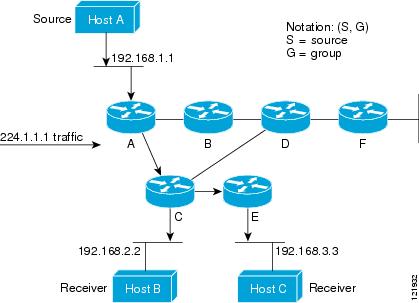
Figure 4 shows an example of an SPT for group 224.1.1.1 rooted at the source, Host A, and connecting two receivers, Hosts B and C.
Figure 4 Source Tree
Using standard notation, the SPT for the example shown in Figure 4 would be (192.168.1.1, 224.1.1.1).
The (S,G) notation implies that a separate SPT exists for each individual source sending to each group—which is correct.
Multicast Distribution Shared Tree
Unlike source trees that have their root at the source, shared trees use a single common root placed at some chosen point in the network. This shared root is called a rendezvous point (RP).
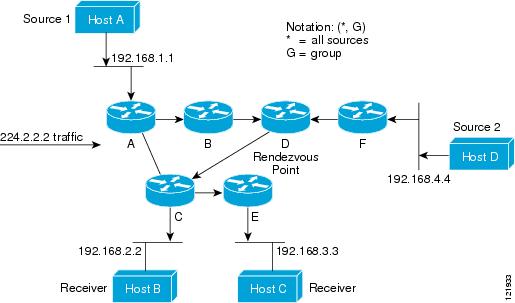
Figure 5 shows a shared tree for the group 224.2.2.2 with the root located at Router D. This shared tree is unidirectional. Source traffic is sent towards the RP on a source tree. The traffic is then forwarded down the shared tree from the RP to reach all of the receivers (unless the receiver is located between the source and the RP, in which case it will be serviced directly).
Figure 5 Shared Distribution Tree
In this example, multicast traffic from the sources, Hosts A and D, travels to the root (Router D) and then down the shared tree to the two receivers, Hosts B and C. Because all sources in the multicast group use a common shared tree, a wildcard notation written as (*, G), pronounced "star comma G," represents the tree. In this case, * means all sources, and G represents the multicast group. Therefore, the shared tree shown in Figure 5 would be written as (*, 224.2.2.2).
Both source trees and shared trees are loop-free. Messages are replicated only where the tree branches. Members of multicast groups can join or leave at any time; therefore the distribution trees must be dynamically updated. When all the active receivers on a particular branch stop requesting the traffic for a particular multicast group, the routers prune that branch from the distribution tree and stop forwarding traffic down that branch. If one receiver on that branch becomes active and requests the multicast traffic, the router will dynamically modify the distribution tree and start forwarding traffic again.
Source Tree Advantage
Source trees have the advantage of creating the optimal path between the source and the receivers. This advantage guarantees the minimum amount of network latency for forwarding multicast traffic. However, this optimization comes at a cost. The routers must maintain path information for each source. In a network that has thousands of sources and thousands of groups, this overhead can quickly become a resource issue on the routers. Memory consumption from the size of the multicast routing table is a factor that network designers must take into consideration.
Shared Tree Advantage
Shared trees have the advantage of requiring the minimum amount of state in each router. This advantage lowers the overall memory requirements for a network that only allows shared trees. The disadvantage of shared trees is that under certain circumstances the paths between the source and receivers might not be the optimal paths, which might introduce some latency in packet delivery. For example, in Figure 5 the shortest path between Host A (source 1) and Host B (a receiver) would be Router A and Router C. Because we are using Router D as the root for a shared tree, the traffic must traverse Routers A, B, D and then C. Network designers must carefully consider the placement of the rendezvous point (RP) when implementing a shared tree-only environment.
In unicast routing, traffic is routed through the network along a single path from the source to the destination host. A unicast router does not consider the source address; it considers only the destination address and how to forward the traffic toward that destination. The router scans through its routing table for the destination address and then forwards a single copy of the unicast packet out the correct interface in the direction of the destination.
In multicast forwarding, the source is sending traffic to an arbitrary group of hosts that are represented by a multicast group address. The multicast router must determine which direction is the upstream direction (toward the source) and which one is the downstream direction (or directions) toward the receivers. If there are multiple downstream paths, the router replicates the packet and forwards it down the appropriate downstream paths (best unicast route metric)—which is not necessarily all paths. Forwarding multicast traffic away from the source, rather than to the receiver, is called Reverse Path Forwarding (RPF). RPF is described in the following section.
Reverse Path Forwarding (RPF)
In unicast routing, traffic is routed through the network along a single path from the source to the destination host. A unicast router does not consider the source address; it considers only the destination address and how to forward the traffic toward that destination. The router scans through its routing table for the destination network and then forwards a single copy of the unicast packet out the correct interface in the direction of the destination.
In multicast forwarding, the source is sending traffic to an arbitrary group of hosts that are represented by a multicast group address. The multicast router must determine which direction is the upstream direction (toward the source) and which one is the downstream direction (or directions) toward the receivers. If there are multiple downstream paths, the router replicates the packet and forwards it down the appropriate downstream paths (best unicast route metric)—which is not necessarily all paths. Forwarding multicast traffic away from the source, rather than to the receiver, is called Reverse Path Forwarding (RPF). RPF is an algorithm used for forwarding multicast datagrams.
Protocol Independent Multicast (PIM) uses the unicast routing information to create a distribution tree along the reverse path from the receivers towards the source. The multicast routers then forward packets along the distribution tree from the source to the receivers. RPF is a key concept in multicast forwarding. It enables routers to correctly forward multicast traffic down the distribution tree. RPF makes use of the existing unicast routing table to determine the upstream and downstream neighbors. A router will forward a multicast packet only if it is received on the upstream interface. This RPF check helps to guarantee that the distribution tree will be loop-free.
RPF Check
When a multicast packet arrives at a router, the router performs an RPF check on the packet. If the RPF check succeeds, the packet is forwarded. Otherwise, it is dropped.
For traffic flowing down a source tree, the RPF check procedure works as follows:
1.
2.
3.
Figure 6 shows an example of an unsuccessful RPF check.
Figure 6 RPF Check Fails
As Figure 6 illustrates, a multicast packet from source 151.10.3.21 is received on serial interface 0 (S0). A check of the unicast route table shows that S1 is the interface this router would use to forward unicast data to 151.10.3.21. Because the packet has arrived on interface S0, the packet is discarded.
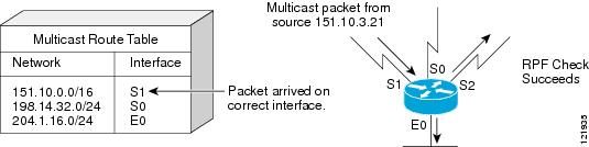
Figure 7 shows an example of a successful RPF check.
Figure 7 RPF Check Succeeds
In this example, the multicast packet has arrived on interface S1. The router refers to the unicast routing table and finds that S1 is the correct interface. The RPF check passes, and the packet is forwarded.
PIM Dense Mode Fallback
If you use IP multicast in mission-critical networks, you should avoid the use of PIM-DM (dense mode).
Dense mode fallback describes the event of the PIM mode changing (falling back) from sparse mode (which requires an RP) to dense mode (which does not use an RP). Dense mode fallback occurs when RP information is lost.
If all interfaces are configured with the ip pim sparse-mode command, there is no dense mode fallback because dense mode groups cannot be created over interfaces configured for sparse mode.
Cause and Effect of Dense Mode Fallback
PIM determines whether a multicast group operates in PIM-DM or PIM-SM mode based solely on the existence of RP information in the group-to-RP mapping cache. If Auto-RP is configured or a bootstrap router (BSR) is used to distribute RP information, there is a risk that RP information can be lost if all RPs, Auto-RP, or the BSR for a group fails due to network congestion. This failure can lead to the network either partially or fully falling back into PIM-DM.
If a network falls back into PIM-DM and AutoRP or BSR is being used, dense mode flooding will occur. Routers that lose RP information will fallback into dense mode and any new states that must be created for the failed group will be created in dense mode.
Effects of Preventing Dense Mode Fallback
Prior to the introduction of PIM-DM fallback prevention, all multicast groups without a group-to-RP mapping would be treated as dense mode.
With the introduction of PIM-DM fallback prevention, the PIM-DM fallback behavior has been changed to prevent dense mode flooding. By default, if all of the interfaces are configured to operate in PIM sparse mode (using the ip pim sparse-mode command), there is no need to configure the no ip pim dm-fallback command (that is, the PIM-DM fallback behavior is enabled by default). If any interfaces are not configured using the ip pim sparse-mode command (for example, using the ip pim sparse-dense-mode command), then the PIM-DM fallback behavior can be explicit disabled using the no ip pim dm-fallback command.
When the no ip pim dm-fallback command is configured or when ip pim sparse-mode is configured on all interfaces, any existing groups running in sparse mode will continue to operate in sparse mode but will use an RP address set to 0.0.0.0. Multicast entries with an RP address set to 0.0.0.0 will exhibit the following behavior:
•
•
•
•
•
•
•
•
Guidelines for Choosing a PIM Mode
Before beginning the configuration process, you must decide which PIM mode needs to be used. This determination is based on the applications you intend to support on your network.
Basic guidelines include the following:
•
•
•
Where to Go Next
•
Additional References
The following sections provide references related to IP multicast.
Related Documents
Location of IP multicast features
IP multicast commands: complete command syntax, command mode, command history, defaults, usage guidelines and examples
MIBs
—
To locate and download MIBs for selected platforms, Cisco IOS releases, and feature sets, use Cisco MIB Locator found at the following URL:
RFCs
RFC 1112
RFC 2113
RFC 2362
Protocol Independent Multicast-Sparse Mode (PIM-SM): Protocol Specification
RFC 3180
Technical Assistance
Feature Information for IP Multicast Technology Overview
Table 2 lists the features in this module and provides links to specific configuration information. Only features that were introduced or modified in Cisco IOS Releases 12.2(1) or later appear in the table.
Not all commands may be available in your Cisco IOS software release. For details on when support for specific commands was introduced, see the command reference documents.
If you are looking for information on a feature in this technology that is not documented here, see the "IP Multicast Features Roadmap."
Cisco IOS software images are specific to a Cisco IOS software release, a feature set, and a platform. Use Cisco Feature Navigator to find information about platform support and Cisco IOS software image support. Access Cisco Feature Navigator (http://www.cisco.com/go/fn). You must have an account on Cisco.com. If you do not have an account or have forgotten your username or password, click Cancel at the login dialog box and follow the instructions that appear.
Note
Table 2 Feature Information for IP Multicast Technology Overview
CCDE, CCENT, CCSI, Cisco Eos, Cisco HealthPresence, Cisco IronPort, the Cisco logo, Cisco Nurse Connect, Cisco Pulse, Cisco SensorBase, Cisco StackPower, Cisco StadiumVision, Cisco TelePresence, Cisco Unified Computing System, Cisco WebEx, DCE, Flip Channels, Flip for Good, Flip Mino, Flipshare (Design), Flip Ultra, Flip Video, Flip Video (Design), Instant Broadband, and Welcome to the Human Network are trademarks; Changing the Way We Work, Live, Play, and Learn, Cisco Capital, Cisco Capital (Design), Cisco:Financed (Stylized), Cisco Store, Flip Gift Card, and One Million Acts of Green are service marks; and Access Registrar, Aironet, AllTouch, AsyncOS, Bringing the Meeting To You, Catalyst, CCDA, CCDP, CCIE, CCIP, CCNA, CCNP, CCSP, CCVP, Cisco, the Cisco Certified Internetwork Expert logo, Cisco IOS, Cisco Lumin, Cisco Nexus, Cisco Press, Cisco Systems, Cisco Systems Capital, the Cisco Systems logo, Cisco Unity, Collaboration Without Limitation, Continuum, EtherFast, EtherSwitch, Event Center, Explorer, Follow Me Browsing, GainMaker, iLYNX, IOS, iPhone, IronPort, the IronPort logo, Laser Link, LightStream, Linksys, MeetingPlace, MeetingPlace Chime Sound, MGX, Networkers, Networking Academy, PCNow, PIX, PowerKEY, PowerPanels, PowerTV, PowerTV (Design), PowerVu, Prisma, ProConnect, ROSA, SenderBase, SMARTnet, Spectrum Expert, StackWise, WebEx, and the WebEx logo are registered trademarks of Cisco Systems, Inc. and/or its affiliates in the United States and certain other countries.
All other trademarks mentioned in this document or website are the property of their respective owners. The use of the word partner does not imply a partnership relationship between Cisco and any other company. (0910R)
Any Internet Protocol (IP) addresses and phone numbers used in this document are not intended to be actual addresses and phone numbers. Any examples, command display output, network topology diagrams, and other figures included in the document are shown for illustrative purposes only. Any use of actual IP addresses or phone numbers in illustrative content is unintentional and coincidental.
© 2005-2009 Cisco Systems, Inc. All rights reserved.