Feedback
Table Of Contents
In-Band and Out-of-Band Signaling
Channelized E1 and T1 on Cisco Devices
Requesting PRI Line and Switch Configuration from a Telco Service Provider
Configuring Channelized E1 ISDN PRI
Configuring Channelized T1 ISDN PRI
Configuring the Serial Interface
Specifying an IP Address for the Interface
Configuring Encapsulation on ISDN PRI
Configuring Network Addressing
Configuring ISDN Calling Number Identification
Overriding the Default TEI Value
Configuring Incoming ISDN Modem Calls
Configuring the ISDN Guard Timer
Configuring Inclusion of the Sending Complete Information Element
Configuring ISDN PRI B-Channel Busyout
Configuring NSF Call-by-Call Support
Configuring Multiple ISDN Switch Types
Configuring B Channel Outgoing Call Order
Performing Configuration Self-Tests
Monitoring and Maintaining ISDN PRI Interfaces
How to Configure Robbed-Bit Signaling for Analog Calls over T1 Lines
Configuring CAS for Analog Calls over E1 Lines
Configuring CAS on a Cisco Router Connected to a PBX or PSTN
Configuring ANI/DNIS Delimiters for CAS Calls on CT1
How to Configure Switched 56K Digital Dial-In over Channelized T1 and Robbed-Bit Signaling
Switched 56K and Analog Modem Calls into T1 CAS
Basic Call Processing Components
How to Configure Switched 56K Services
How to Configure E1 R2 Signaling
Configuring E1 R2 Signaling for Voice
Troubleshooting E1 R2 Signaling
Enabling R1 Modified Signaling in Taiwan
R1 Modified Signaling Topology
R1 Modified Signaling Configuration Task List
Configuring R1 Modified Signaling on a T1 Interface
Configuring R1 Modified Signaling on an E1 Interface
Troubleshooting Channelized E1 and T1 Channel Groups
Configuration Examples for Channelized E1 and Channelized T1
Global ISDN, BRI, and PRI Switch Example
Global ISDN and Multiple BRI and PRI Switch Using TEI Negotiation Example
NSF Call-by-Call Support Example
PRI on a Cisco AS5000 Series Access Server Example
ISDN B-Channel Busyout Example
Multiple ISDN Switch Types Example
Outgoing B-Channel Ascending Call Order Example
Static TEI Configuration Example
Call Reject Configuration Examples
ISDN Cause Code Override and Guard Timer Example
PRI Groups and Channel Groups on the Same Channelized T1 Controller Example
Allocating All Channels for Robbed-Bit Signaling Example
Mixing and Matching Channels—Robbed-Bit Signaling and Channel Grouping
Switched 56K Configuration Examples
Switched 56K T1 Controller Procedure
Mixture of Switched 56K and Modem Calls over CT1 CAS Example
Switched 56K and Analog Modem Calls over Separate T1 CAS Lines Example
Comprehensive Switched 56K Startup Configuration Example
Allocating All Channels for CAS Example
Mixing and Matching Channels—CAS and Channel Grouping Example
R1 Modified Signaling Using an E1 Interface Example
R1 Modified Signaling for Taiwan Configuration Example
Configuring ISDN PRI
This chapter describes how to configure channelized E1 and channelized T1 for ISDN PRI and for two types of signaling to support analog calls over digital lines. This information is included in the following sections:
•
Monitoring and Maintaining ISDN PRI Interfaces
•
•
•
•
•
•
In addition, this chapter describes how to run interface loopback diagnostics on channelized E1 and channelized T1 lines. For more information, see the "How to Configure Switched 56K Digital Dial-In over Channelized T1 and Robbed-Bit Signaling" section later in this chapter, and the Cisco IOS Interface Configuration Guide, Release 12.2.
For hardware technical descriptions and for information about installing the controllers and interfaces, refer to the hardware installation and maintenance publication for your particular product.
To identify the hardware platform or software image information associated with a feature, use the Feature Navigator on Cisco.com to search for information about the feature or refer to the software release notes for a specific release. For more information, see the "Identifying Supported Platforms" section in the "Using Cisco IOS Software" chapter.
For a complete description of the channelized E1/T1 commands in this chapter, refer to the Cisco IOS Dial Technologies Command Reference. To locate documentation of other commands that appear in this chapter, use the command reference master index or search online.
Signaling Overview
Channelized T1 and channelized E1 can be configured for ISDN PRI, synchronous serial, and asynchronous serial communications.
Channelized T1 and channelized E1 are supported by corresponding controllers. Each T1 or E1 controller has one physical network termination, but it can have many virtual interfaces, depending on the configuration.
In-Band and Out-of-Band Signaling
The terms in-band and out-of-band indicate whether various signals—which are used to set up, control, and terminate calls—travel in the same channel (or band) with voice calls or data made by the user, or whether those signals travel in a separate channel (or band).
ISDN, which uses the D channel for signaling and the B channels for user data, fits into the out-of-band signaling category.
Robbed-bit signaling, which uses bits from specified frames in the user data channel for signaling, fits into the in-band signaling category.
Channel-associated signaling (CAS), which uses E1 time slot 16 (the D channel) for signaling, fits into the out-of-band signaling category.
Channelized E1 and T1 on Cisco Devices
You can allocate the available channels for channelized E1 or T1 in the following ways:
•
•
•
•
•
See the sections "PRI Groups and Channel Groups on the Same Channelized T1 Controller Example," "Robbed-Bit Signaling Examples," and the "ISDN CAS Examples" at the end of this chapter.
How to Configure ISDN PRI
This section describes tasks that are required to get ISDN PRI up and running. This section does not address routing issues, dialer configuration, and dial backup. For information about those topics, see the chapters in the "Dial-on-Demand Routing" part of this manual.
To configure ISDN PRI, perform the tasks in the following sections:
•
•
•
•
•
•
•
•
See the section "Monitoring and Maintaining ISDN PRI Interfaces" later in this chapter for tips on maintaining the ISDN PRI interface. See the end of this chapter for the "ISDN PRI Examples" section.
Note
Requesting PRI Line and Switch Configuration from a Telco Service Provider
Before configuring ISDN PRI on your Cisco router, you need to order a correctly provisioned ISDN PRI line from your telecommunications service provider.
This process varies dramatically from provider to provider on a national and international basis. However, some general guidelines follow:
•
•
•
Table 1 provides a sample of the T1 configuration attributes you might request for a PRI switch used in North America.
Configuring Channelized E1 ISDN PRI
To configure ISDN PRI on a channelized E1 controller, use the following commands beginning in global configuration mode:
Step 1
Router(config)# isdn switch-type switch-type
Selects a service provider switch type that accommodates PRI. (See Table 2 for a list of supported switch type keywords.)
Step 2
Router(config)# controller e1 slot/port
or
Router(config)# controller e1 number
Defines the controller location in the Cisco 7200 or Cisco 7500 series router by slot and port number.
Defines the controller location in the Cisco 4000 series or the Cisco AS5200 universal access server by unit number.1
Step 3
Router(config-controller)# framing crc4
Defines the framing characteristics as cyclic redundancy check 4 (CRC4).
Step 4
Router(config-controller)# linecode hdb3
Defines the line code as high-density bipolar 3 (HDB3).
Step 5
Router(config-controller)# pri-group [timeslots range]
Configures ISDN PRI.
1 Controller numbers range from 0 to 2 on the Cisco 4000 series and from 1 to 2 on the Cisco AS5000 series access server.
If you do not specify the time slots, the specified controller is configured for 30 B channels and 1 D channel. The B channel numbers range from 1 to 31; channel 16 is the D channel for E1. Corresponding serial interfaces numbers range from 0 to 30. In commands, the D channel is interface serial controller-number:15. For example, interface serial 0:15.
Table 2 lists the keywords for the supported service provider switch types to be used in Step 1 above.
Note
Configuring Channelized T1 ISDN PRI
To configure ISDN PRI on a channelized T1 controller, use the following commands beginning in global configuration mode:
Step 1
Router(config)# isdn switch-type switch-type
Selects a service provider switch type that accommodates PRI. (Refer to Table 2 for a list of supported PRI switch type keywords.)
Step 2
Router(config)# controller t1 slot/port
or
Router(config)# controller t1 number
Specifies a T1 controller on a Cisco 7500.
Specifies a T1 controller on a Cisco 4000.1
Step 3
Router(config-controller)# framing esf
Defines the framing characteristics as Extended Superframe Format (ESF).
Step 4
Router(config-controller)# linecode b8zs
Defines the line code as binary 8 zero substitution (B8ZS).
Step 5
Router(config-controller)# pri-group [timeslots range]2
Configures ISDN PRI.
If you do not specify the time slots, the controller is configured for 23 B channels and 1 D channel.
1 Controller numbers range from 0 to 2 on the Cisco 4000 series and from 1 to 2 on the Cisco AS5000 series.
2 On channelized T1, time slots range from 1 to 24. You can specify a range of time slots (for example, pri-group timeslots 12-24) if other time slots are used for non-PRI channel groups.
If you do not specify the time slots, the specified controller is configured for 24 B channels and 1 D channel. The B channel numbers range from 1 to 24; channel 24 is the D channel for T1. Corresponding serial interfaces numbers range from 0 to 23. In commands, the D channel is interface serial controller-number:23. For example, interface serial 0:23.
Configuring the Serial Interface
When you configure ISDN PRI on the channelized E1 or channelized T1 controller, in effect you create a serial interface that corresponds to the PRI group time slots. This interface is a logical entity associated with the specific controller. After you create the serial interface by configuring the controller, you must configure the D channel serial interface. The configuration applies to all the PRI B channels (time slots).
To configure the D channel serial interface, perform the tasks in the following sections:
•
•
•
•
•
•
•
•
•
•
•
Specifying an IP Address for the Interface
To configure the D channel serial interface created for ISDN PRI, use the following commands beginning in global configuration mode:
When you configure the D channel, its configuration is applied to all the individual B channels.
Configuring Encapsulation on ISDN PRI
PPP encapsulation is configured for most ISDN communication. However, the router might require a different encapsulation for traffic sent over a Frame Relay or X.25 network, or the router might need to communicate with devices that require a different encapsulation protocol.
Configure encapsulation as described in one of the following sections:
•
•
•
In addition, the router can be configured for automatic detection of encapsulation type on incoming calls. To configure this feature, complete the tasks in the "Configuring Automatic Detection of Encapsulation Type of Incoming Calls" section.
Note
Configuring PPP Encapsulation
Each ISDN B channel is treated as a serial line and supports HDLC and PPP encapsulation. The default serial encapsulation is HDLC. To configure PPP encapsulation, use the following command in interface configuration mode:
Configuring Encapsulation for Frame Relay or X.25 Networks
If traffic from this ISDN interface crosses a Frame Relay or X.25 network, the appropriate addressing and encapsulation tasks must be completed as required for Frame Relay or X.25 networks.
See the sections "Sending Traffic over Frame Relay, X.25, or LAPB Networks" in the chapter "Configuring Legacy DDR Spokes" for more information about addressing, encapsulation, and other tasks necessary to configure Frame Relay or X.25 networks.
Configuring Encapsulation for Combinet Compatibility
Historically, Combinet devices supported only the Combinet Proprietary Protocol (CPP) for negotiating connections over ISDN B channels. To enable Cisco routers to communicate with those Combinet bridges, the Cisco IOS software supports the CPP encapsulation type.
To enable routers to communicate over ISDN interfaces with Combinet bridges that support only CPP, use the following commands in interface configuration mode:
Most Combinet devices support PPP. Cisco routers can communicate over ISDN with these devices by using PPP encapsulation, which supports both routing and fast switching.
Cisco 700 and 800 series routers and bridges (formerly Combinet devices) support only IP, IPX, and bridging. For AppleTalk, Cisco routers automatically perform half-bridging with Combinet devices. For more information about half-bridging, see the section "Configuring PPP Half-Bridging" in the "Configuring Media-Independent PPP and Multilink PPP" chapter in this publication.
Cisco routers can also half-bridge IP and IPX with Combinet devices that support only CPP. To configure this feature, you only need to set up the addressing with the ISDN interface as part of the remote subnet; no additional commands are required.
Configuring Automatic Detection of Encapsulation Type of Incoming Calls
You can enable a serial or ISDN interface to accept calls and dynamically change the encapsulation in effect on the interface when the remote device does not signal the call type. For example, if an ISDN call does not identify the call type in the Lower Layer Compatibility fields and is using an encapsulation that is different from the one configured on the interface, the interface can change its encapsulation type at that time.
This feature enables interoperation with ISDN terminal adapters that use V.120 encapsulation but do not signal V.120 in the call setup message. An ISDN interface that by default answers a call as synchronous serial with PPP encapsulation can change its encapsulation and answer such calls.
Automatic detection is attempted for the first 10 seconds after the link is established or the first 5 packets exchanged over the link, whichever is first.
To enable automatic detection of encapsulation type, use the following command in interface configuration mode:
Router(config-if)# autodetect encapsulation encapsulation-type
Enables automatic detection of encapsulation type on the specified interface.
You can specify one or more encapsulations to detect. Cisco IOS software currently supports automatic detection of PPP and V.120 encapsulations.
Configuring Network Addressing
When you configure networking, you specify how to reach the remote recipient. To configure network addressing, use the following commands in interface configuration mode:
Australian networks allow semipermanent connections between customer routers with PRIs and the TS-014 ISDN PRI switches in the exchange. Semipermanent connections are offered at better pricing than leased lines.
Packets that are permitted by the access list specified by the dialer-list command are considered interesting and cause the router to place a call to the identified destination protocol address.
Note
For more information about defining outgoing call numbers, see the sections "Configuring Access Control for Outgoing Calls" in the chapters "Configuring Legacy DDR Spokes" or "Configuring Legacy DDR Hubs" later in this publication.
Configuring ISDN Calling Number Identification
A router might need to supply the ISDN network with a billing number for outgoing calls. Some networks offer better pricing on calls in which the number is presented. When configured, the calling number information is included in the outgoing Setup message.
To configure the interface to identify the billing number, use the following command in interface configuration mode:
Router(config-if)# isdn calling-number calling-number
Specifies the calling party number.
This command can be used with all ISDN PRI switch types.
Overriding the Default TEI Value
You can configure ISDN terminal endpoint identifier (TEI) negotiation on individual ISDN interfaces. TEI negotiation is useful for switches that may deactivate Layers 1 or 2 when there are no active calls. Typically, this setting is used for ISDN service offerings in Europe and connections to DMS 100 switches that are designed to initiate TEI negotiation.
By default, TEI negotiation occurs when the router is powered up. The TEI negotiation value configured on an interface overrides the default or global TEI value. On PRI interfaces connecting to DMS 100 switches, the router will change the default TEI setting to isdn tei first-call. To apply TEI negotiation to a specific PRI interface, use the following command in interface configuration mode:
Router(config-if)# isdn tei [first-call | powerup]
Determines when ISDN TEI negotiation occurs.
Configuring a Static TEI
Depending on the telephone company you subscribe to, you may have a dynamically or statically assigned terminal endpoint identifier (TEI) for your ISDN service. By default, TEIs are dynamic in Cisco routers. To configure the TEI as a static configuration, use the following command in interface configuration mode:
Router(config-if)# isdn static-tei tei-number
Configures a static ISDN Layer 2 TEI over the D channel.
Configuring Incoming ISDN Modem Calls
All incoming ISDN analog modem calls that come in on an ISDN PRI receive signaling information from the ISDN D channel. The D channel is used for circuit-switched data calls and analog modem calls.
To enable all incoming ISDN voice calls to access the call switch module and integrated modems, use the following command in interface configuration mode:
Router(config-if)# isdn incoming-voice {modem [56 | 64]}
Routes incoming ISDN modem calls to the call switch module.
The settings for the isdn incoming-voice interface command determine how a call is handled based on bearer capability information, as follows:
•
•
•
Refer to the Cisco IOS Voice, Video, and Fax Configuration Guide and Cisco IOS Voice, Video, and Fax Command Reference, Release 12.2, for more information about using the isdn incoming-voice interface configuration command to configure incoming ISDN voice and data calls.
Filtering Incoming ISDN Calls
You may find it necessary to configure your network to reject an incoming call with some specific ISDN bearer capability such as nonspeech or nonaudio data. To filter out unwanted call types, use the following command in interface configuration mode:
Note
Verifying the Call Reject Configuration
To verify that calls are being rejected, perform the following steps:
Step 1
•
•
•
•
Step 2
Router(config)# interface serial 4:23Router(config-if)# isdn reject dataRouter(config-if)# ^ZStep 3
ISDN <TYPE:NUMBER>: Rejecting call id <CALLID> isdn calltype screening failed
Step 4
Step 5
Configuring the ISDN Guard Timer
Beginning in Cisco IOS Release 12.2, the ISDN guard timer feature implements a new managed timer for ISDN calls. Because response times for authentication requests can vary, for instance when using DNIS authentication, the guard timer allows you to control the handling of calls.
To configure the ISDN guard timer, use the following command in interface configuration mode:
For more information about configuring RADIUS, and to see sample ISDN PRI guard timer configurations, refer to the Cisco IOS Security Configuration Guide.
Configuring Inclusion of the Sending Complete Information Element
In some geographic locations, such as Hong Kong and Taiwan, ISDN switches require that the Sending Complete information element be included in the outgoing Setup message to indicate that the entire number is included. This information element is generally not required in other locations.
To configure the interface to include the Sending Complete information element in the outgoing call Setup message, use the following command in interface configuration mode:
Router(config-if)# isdn sending-complete
Includes the Sending Complete information element in the outgoing call Setup message.
Configuring ISDN PRI B-Channel Busyout
To allow the busyout of individual ISDN PRI B channels, use the following commands beginning in global configuration mode:
Configuring NSF Call-by-Call Support
Network-Specific Facilities (NSF) are used to request a particular service from the network or to provide an indication of the service being provided. Call-by-call support means that a B channel can be used for any service; its use is not restricted to a certain preconfigured service, such as incoming 800 calls or an outgoing 800 calls. This specific NSF call-by-call service supports outgoing calls configured as voice calls.
This NSF call-by-call support feature is vendor-specific; only routers connected to AT&T Primary-4ESS switches need to configure this feature. This feature is supported on channelized T1.
To enable the router for NSF call-by-call support and, optionally, to place outgoing voice calls, complete the following steps:
Step 1
Step 2
Step 3
To define the dialer map class for the dialing plan, use the following commands beginning in global configuration mode:
Note
Table 3 lists the NSF dialing plans and supported services offered on AT&T Primary-4ESS switches.
Table 3 NSF Supported Services on AT&T Primary-4ESS Switches
Software Defined Network (SDN)1
Yes
Yes
Global SDN
MEGACOMM
No
Yes
Yes
ACCUNET
Yes
Yes
Yes
1 The dialing plan terminology in this table is defined and used by AT&T.
Configuring Multiple ISDN Switch Types
You can apply an ISDN switch type on a per-interface basis, thus extending the existing global isdn switch-type command to the interface level. This allows PRI and BRI to run simultaneously on platforms that support both interface types.
A global ISDN switch type is required and must be configured on the router before you can configure a switch type on an interface.
To configure multiple ISDN switch types for a PRI interface using a channelized E1 or channelized T1 controller, use the following command in global configuration mode:
You must ensure that the ISDN switch type is valid for the ISDN interfaces on the router. Table 2 lists valid ISDN switch types for BRI and PRI interfaces.
Note
The following restrictions apply to the Multiple ISDN Switch Types feature:
•
•
•
•
•
If, for example, you reconfigure the router to use global switch type keyword basic-net3, the router will apply the primary-net5 ISDN switch type to PRI interfaces and the basic-net3 ISDN switch type to any BRI interfaces. You can override the default switch assignment by configuring a different ISDN switch type on the associated interface.
Configuring B Channel Outgoing Call Order
You can configure the router to select the first available B channel in ascending order (channel B1) or descending order (channel B23 for a T1 and channel B30 for an E1). To configure the optional task of selecting B channel order for outgoing calls for PRI interface types, use the following command in interface configuration mode:
Router(config-if)# isdn bchan-number-order {ascending | descending}
Enables B channel selection for outgoing calls on a PRI interface (optional).
Before configuring the ISDN PRI on your router, check with your service vendor to determine if the ISDN trunk call selection is configured for ascending or descending order. If there is a mismatch between the router and switch with regard to channel availability, the switch will send back an error message stating the channel is not available. By default, the router will select outgoing calls in descending order.
Performing Configuration Self-Tests
To test the ISDN configuration, use the following EXEC commands as needed. Refer to the Cisco IOS Debug Command Reference for information about the debug commands.
Monitoring and Maintaining ISDN PRI Interfaces
To monitor and maintain ISDN interfaces, use the following EXEC commands as needed:
How to Configure Robbed-Bit Signaling for Analog Calls over T1 Lines
Some Cisco access servers support robbed-bit signaling for receiving and sending analog calls on T1 lines. Robbed-bit signaling emulates older analog trunk and line in-band signaling methods that are sent in many networks.
In countries that support T1 framing (such as the United States and Canada), many networks send supervisory and signaling information to each other by removing the 8th bit of each time slot of the 6th and 12th frame for superframe (SF) framing. For networks supporting extended superframe (ESF) framing, the 6th, 12th, 18th, and 24th frames are affected. This additional signaling information is added to support channel banks in the network that convert various battery and ground operations on analog lines into signaling bits.
Robbed-bit signaling configured on a Cisco access server enables integrated modems to answer and send analog calls. Robbed bits are forwarded over digital lines. To support analog signaling over T1 lines, robbed-bit signaling must be enabled.
Note
The Cisco access server has two controllers: controller T1 1 and controller T1 0, which must be configured individually.
To configure robbed-bit signaling support for calls made and received, use the following commands beginning in global configuration mode:
If you want to configure robbed-bit signaling on the other T1 controller, repeat Steps 1 through 7, making sure in Step 5 to select T1 controller line 1 as the secondary clock source.
If you want to configure ISDN on the other controller, see the section "How to Configure ISDN PRI" in this chapter. If you want to configure channel groupings on the other controller, see the chapter "Configuring Synchronous Serial Ports" in this publication; specify the channel groupings when you specify the interface.
See the section "Robbed-Bit Signaling Examples" at the end of this chapter for configuration examples.
How to Configure CAS
The following sections describe how to configure channel-associated signaling in Cisco networking devices for both channelized E1 and T1 lines:
CAS on Channelized E1
Cisco access servers and access routers support CAS for channelized E1 lines, which are commonly deployed in networks in Latin America, Asia, and Europe. CAS is configured to support channel banks in the network that convert various battery and ground operations on analog lines into signaling bits, which are forwarded over digital lines.
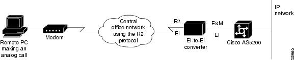
CAS is call signaling that is configured on an E1 controller and enables the access server to send or receive analog calls. The signaling uses the16th channel (time slot); thus, CAS fits in the out-of-band signaling category.
Once CAS is configured on a single E1 controller, remote users can simultaneously dial in to the Cisco device through networks running the R2 protocol (see specifications for your particular network device for the number of dialins supported).
The R2 protocol is an international signaling standard for analog connections. Because R2 signaling is not supported in the Cisco access servers, an E1-to-E1 converter is required.
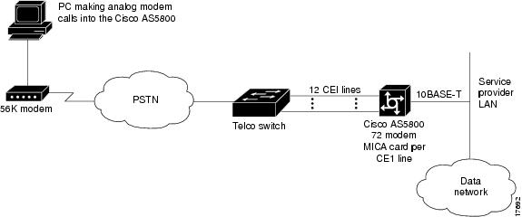
Figure 1 illustrates that, because the Cisco access servers have more than one physical E1 port on the dual E1 PRI board, up to 60 simultaneous connections can be made through one dual E1 PRI board.
Figure 1 Remote PC Accessing Network Resources Through the Cisco AS5000 Series Access Server
Note
Note
Configuring CAS for Analog Calls over E1 Lines
To configure the E1 controllers in the Cisco access servers, use the following commands beginning in global configuration mode:
Step 1
Router(config)# controller e1 number
Defines the controller location in the Cisco access server by unit number (choices for the number argument are 1 or 2) and begins controller configuration mode.
Step 2
Router(config-controller)# cas-group channel-number timeslots range type signal
Configures CAS and the R2 signaling protocol on a specified number of time slots.
Step 3
Router(config-controller)# framing crc4
Defines the framing characteristics as CRC4.
Step 4
Router(config-controller)# linecode hdb3
Defines the line code as HDB3.
Step 5
Router(config-controller)# clock source line primary1
Specifies one E1 line to serve as the primary or most stable clock source line.
1 Specify the other E1 line as the secondary clock source using the clock source line secondary command.
If you do not specify the time slots, CAS is configured on all 30 B channels and one D channel on the specified controller.
See the section "ISDN CAS Examples" for configuration examples.
Configuring CAS on a Cisco Router Connected to a PBX or PSTN
To define E1 channels for the CAS method by which the router connects to a PBX or PSTN, use the following commands beginning in global configuration mode:
Step 1
Specifies the E1 controller that you want to configure with R2 signaling and begins controller configuration.
Step 2
Router(config-controller)# ds0-group ds0-group-no
timeslots timeslot-list type {e&m-immediate |
e&m-delay | e&m-wink | fxs-ground-start |
fxs-loop-start |fxo-ground-start | fxo-loop-start}
Configures channel-associated signaling and the signaling protocol on a specified number of time slots.
Step 3
Defines the framing characteristics as cyclic redundancy check 4 (CRC4).
Step 4
Defines the line code as high-density bipolar 3 (HDB3).
Step 5
Specifies one E1 line to serve as the primary or most stable clock source line.
1 Specify the other E1 line as the secondary clock source using the clock source line secondary command.
If you do not specify the time slots, channel-associated signaling is configured on all 30 B channels and one D channel on the specified controller.
CAS on T1 Voice Channels
Various types of CAS signaling are available in the T1 world. The most common forms of CAS signaling are loop-start, ground-start, and recEive and transMit (E&M). The biggest disadvantage of CAS signaling is its use of user bandwidth to perform signaling functions. CAS signaling is often referred to as robbed-bit-signaling because user bandwidth is being "robbed" by the network for other purposes. In addition to receiving and placing calls, CAS signaling also processes the receipt of DNIS and ANI information, which is used to support authentication and other functions.
This configuration allows the Cisco access servers to provide the automatic number identification/dialed number identification service (ANI/DNIS) delimiter on incoming T1/CAS trunk lines. The digit collection logic in the call switching module (CSM) for incoming T1 CAS calls in dual tone multifrequency (DTMF) is modified to process the delimiters, the ANI digits, and the DNIS digits.
As part of the configuration, a CAS signaling class with the template to process ANI/DNIS delimiters has to be defined. This creates a signaling class structure which can be referred to by its name.
This feature is only functional in a T1 CAS configured for E&M-feature group b (wink start). E&M signaling is typically used for trunks. It is normally the only way that a central office (CO) switch can provide two-way dialing with direct inward dialing. In all the E&M protocols, off-hook is indicated by A=B=1, and on-hook is indicated by A=B=0. If dial pulse dialing is used, the A and B bits are pulsed to indicate the addressing digits.
For this feature, here is an example of configuring for E&M-feature group b:
ds0-group 1 timeslots 1-24 type e&m-fgb dtmf dnisIn the original Wink Start protocol, the terminating side responds to an off-hook from the originating side with a short wink (transition from on-hook to off-hook and back again). This wink tells the originating side that the terminating side is ready to receive addressing digits. After receiving addressing digits, the terminating side then goes off-hook for the duration of the call. The originating endpoint maintains off-hook for the duration of the call.
Configuring ANI/DNIS Delimiters for CAS Calls on CT1
To configure the signaling class and ANI/DNIS delimiters, use the following commands beginning in global configuration mode:
To disable the delimiter, use the command no class under the cas-custom configuration.
To remove the signaling class, use the configuration command no signaling-class cas. When removing a signaling class, make sure the signaling class is no longer used by any controllers; otherwise, the following warning will be displayed:
% Can't delete, signaling class test is being usedHow to Configure Switched 56K Digital Dial-In over Channelized T1 and Robbed-Bit Signaling
Internet service providers (ISPs) can provide switched 56-kbps access to their customers using a Cisco AS5000 series access server. Switched 56K digital dial-in enables many services for ISPs. When using traditional ISDN PRI, the access server uses the bearer capability to determine the type of service. However when providing switched 56K over a CT1 RBS connection, the digital signal level 0 (DS0s) in the access server can be configured to provide either modem or 56-kbps data service. The dial-in user can access a 56-kbps data connection using either an ISDN BRI connection or a 2- or 4-wire switched 56-kbps connection. The telco to which the access server connects must configure its switches to route 56-kbps data calls and voice (modem) calls to the appropriate DS0.
Likewise, an enterprise can provide switched 56-kbps digital dial-in services to its full time telecommuters or small remote offices using ISDN PRI or a CT1 RBS connection.
Switched 56K digital dial-in offers the following benefits:
•
•
The following prerequisites apply to the Switched 56K Digital Dial-In feature:
•
•
•
•
The following restrictions apply to Switched 56K digital dial-in:
•
•
•
•
Switched 56K Scenarios
The following scenarios are provided to show multiple applications for supporting switched 56K over T1 CAS:
•
•
Switched 56K and Analog Modem Calls into T1 CAS
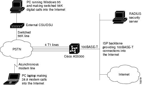
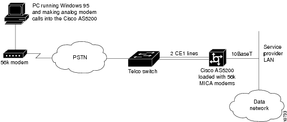
Figure 2 shows a sample network scenario using switched 56K. Two remote PCs are dialing in to the same Cisco access server to get access to the Internet. The desktop PC is making switched 56K digital calls through an external CSU/DSU. The laptop PC is making analog modem calls through a 28.8-kbps modem. The Cisco access server dynamically assigns IP addresses to each node and forwards data packets off to the switched 56K channels and onboard modems respectively.
Figure 2 PCs Making Switched 56K and Analog Modem Calls into a Cisco AS5000 Series Access Server
For the startup running configuration on the Cisco access server shown in Figure 2, see the section "Comprehensive Switched 56K Startup Configuration Example" later in this chapter.
Basic Call Processing Components
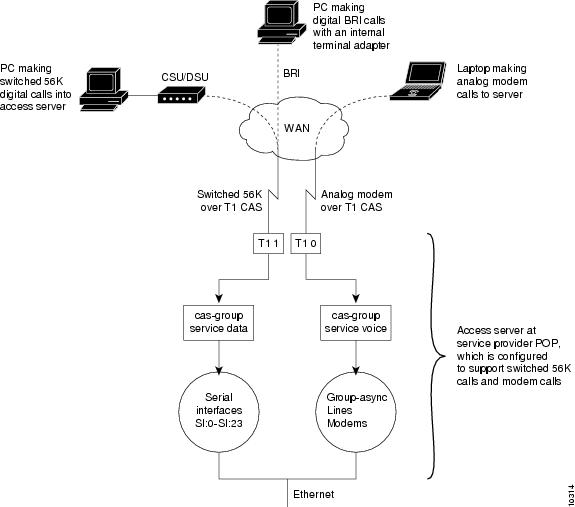
Figure 3 shows the basic components that process switched 56K calls and analog modem calls on board a Cisco access server. Switched 56K and modem calls are signaling using robbed-bit signaling. Digital switched 56K calls utilize logical serial interfaces just like in ISDN PRI. Modem calls utilize asynchronous interfaces, lines, and modems.
Note
Figure 3 Processing Components for Switched 56K Calls Versus Analog Modem Calls
Note
ISDN BRI Calls into T1 CAS
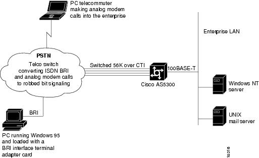
Figure 4 shows how switched 56K functionality can be used to forward ISDN BRI network traffic to a Cisco access server that is configured for switched 56K robbed-bit signaling over CT1.
Note
Figure 4 Remote PC Making BRI Digital Calls via Switched 56K to a Cisco AS5000 Series Access Server
For a configuration example on the Cisco access server, see the section "Comprehensive Switched 56K Startup Configuration Example" at the end of this chapter.
How to Configure Switched 56K Services
This section describes how to configure switched 56K services on a Cisco access server. After the cas-group command is enabled for switched 56K services, a logical serial interface is automatically created for each 56K channel, which must also be configured.
To configure an access server to support switched 56K digital calls, use the following commands beginning in global configuration mode:
For configuration examples, see the section "Switched 56K Configuration Examples" later in this chapter.
How to Configure E1 R2 Signaling
R2 signaling is an international signaling standard that is common to channelized E1 networks. However, there is no single signaling standard for R2. The International Telecommunication Union Telecommunication Standardization Sector (ITU-T) Q.400-Q.490 recommendation defines R2, but a number of countries and geographic regions implement R2 in entirely different ways. Cisco addresses this challenge by supporting many localized implementations of R2 signaling in its Cisco IOS software.
The following sections offer pertinent information about the E1 R2 signaling feature:
•
•
E1 R2 Signaling Overview
R2 signaling is channelized E1 signaling used in Europe, Asia, and South America. It is equivalent to channelized T1 signaling in North America. There are two types of R2 signaling: line signaling and interregister signaling. R2 line signaling includes R2 digital, R2 analog, and R2 pulse. R2 interregister signaling includes R2 compelled, R2 noncompelled, and R2 semicompelled. These signaling types are configured using the cas-group command for Cisco access servers, and the ds0-group command for Cisco routers.
Many countries and regions have their own E1 R2 variant specifications, which supplement the ITU-T Q.400-Q.490 recommendation for R2 signaling. Unique E1 R2 signaling parameters for specific countries and regions are set by entering the cas-custom channel command followed by the country name command.
The Cisco E1 R2 signaling default is ITU, which supports the following countries: Denmark, Finland, Germany, Russia (ITU variant), Hong Kong (ITU variant), and South Africa (ITU variant). The expression "ITU variant" means that there are multiple R2 signaling types in the specified country, but Cisco supports the ITU variant.
Cisco also supports specific local variants of E1 R2 signaling in the following regions, countries, and corporations:
•
•
•
•
•
•
•
•
•
•
•
•
•
•
•
•
•
•
•
•
•
•
•
•
•
•
•
•
•
•
•
•
•
1 Cisco 3620 and 3640 series routers only.
2 Includes Croatia, Russia, and Slovak Republic.
Note
The following are benefits of E1 R2 signaling:
•
•
Cisco's implementation of R2 signaling has DNIS support turned on by default. If you enable the ani option, the collection of DNIS information is still performed. Specifying the ani option does not disable DNIS collection. DNIS is the number being called. ANI is the number of the caller. For example, if you are configuring router A to call router B, then the DNIS number is assigned to router B, the ANI number is assigned to router A. ANI is similar to Caller ID.
Figure 5 shows a sample network topology for using E1 R2 signaling with a Cisco AS5800. All four controllers on the access server are configured with R2 digital signaling. Additionally, localized R2 country settings are enabled on the access server.
Figure 5 Service Provider Using E1 R2 Signaling and a Cisco AS5800
Figure 6 shows a sample network topology for using E1 R2 signaling for voice transfers with a Cisco 2600, 3600, or 7200 series router. All the controllers on the router are configured with R2 digital signaling. Additionally, localized R2 country settings are enabled on the router.
Figure 6 E1 R2 Connections for the Cisco 2600/3600/7200 Series Routers
Configuration examples are supplied in the "Configuration Examples for Channelized E1 and Channelized T1" section at the end of this chapter.
Configuring E1 R2 Signaling
To configure support for E1 R2 signaling on the Cisco access servers, use the following commands beginning in global configuration mode:
For an E1 R2 configuration example, see the section "E1 R2 Signaling Procedure."
Configuring E1 R2 Signaling for Voice
To configure E1 R2 signaling on systems that will be configured for voice, use the following commands beginning in global configuration mode:
Monitoring E1 R2 Signaling
To monitor E1 R2 signaling, use the following commands in EXEC mode as needed:
or
Router> show controllers e1 numberDisplays the status for all controllers or a specific controller. Be sure the status indicates the controller is up and there are no alarms or errors (lines 2, 4, 9, and 10, as shown immediately below in the "Monitoring E1 R2 Using the show controllers e1 Command" section).
Displays status for a specific modem, as shown below in the "Monitoring E1 R2 Signaling Using the show modem csm Command" section.
Monitoring E1 R2 Using the show controllers e1 Command
Router# show controllers e1 0E1 0 is up.Applique type is Channelized E1 - balancedNo alarms detected.Version info of Slot 0: HW: 2, Firmware: 4, PLD Rev: 2Manufacture Cookie is not programmed.Framing is CRC4, Line Code is HDB3, Clock Source is Line Primary.Data in current interval (785 seconds elapsed):0 Line Code Violations, 0 Path Code Violations0 Slip Secs, 0 Fr Loss Secs, 0 Line Err Secs, 0 Degraded Mins0 Errored Secs, 0 Bursty Err Secs, 0 Severely Err Secs, 0 Unavail SecsTotal Data (last 13 15 minute intervals):0 Line Code Violations, 0 Path Code Violations,0 Slip Secs, 12 Fr Loss Secs, 0 Line Err Secs, 0 Degraded Mins,0 Errored Secs, 0 Bursty Err Secs, 0 Severely Err Secs, 12 Unavail SecsMonitoring E1 R2 Signaling Using the show modem csm Command
Router# show modem csm 1/0MODEM_INFO: slot 1, port 0, unit 0, tone r2-compelled, modem_mask=0x0000, modem_port_offset=0tty_hwidb=0x60E63E4C, modem_tty=0x60C16F04, oobp_info=0x00000000, modem_pool=0x60BC60CCmodem_status(0x0002): VDEV_STATUS_ACTIVE_CALL.csm_state(0x0205)=CSM_IC5_CONNECTED, csm_event_proc=0x600CFF70, current call thru CAS lineinvalid_event_count=0, wdt_timeout_count=0wdt_timestamp_started is not activatedwait_for_dialing:False, wait_for_bchan:Falsepri_chnl=TDM_PRI_STREAM(s0, u3, c7), modem_chnl=TDM_MODEM_STREAM(s1, c0)dchan_idb_start_index=0, dchan_idb_index=0, call_id=0x0239, bchan_num=6csm_event=CSM_EVENT_DSX0_CONNECTED, cause=0x0000ring_no_answer=0, ic_failure=0, ic_complete=3dial_failure=0, oc_failure=0, oc_complete=0oc_busy=0, oc_no_dial_tone=0, oc_dial_timeout=0remote_link_disc=2, stat_busyout=2, stat_modem_reset=0oobp_failure=0call_duration_started=00:04:56, call_duration_ended=00:00:00, total_call_duration=00:01:43The calling party phone number =The called party phone number = 9993003total_free_rbs_timeslot = 0, total_busy_rbs_timeslot = 0, total_dynamic_busy_rbs_timeslot = 0, total_static_busy_rbs_timeslot = 0, min_free_modem_threshold = 0Verifying E1 R2 Signaling
To verify the E1 R2 signaling configuration, enter the show controller e1 command to view the status for all controllers, or enter the show controller e1 slot/port command to view the status for a particular controller. Make sure that the status indicates that the controller is up (line 2 in the following example) and that no alarms (line 6 in the following example) or errors (lines 9, 10, and 11 in the following example) have been reported.
Router# show controller E1 1/0E1 1/0 is up.Applique type is Channelized E1Cablelength is short 133Description: E1 WIC card AlphaNo alarms detected.Framing is CRC4, Line Code is HDB3, Clock Source is Line Primary.Data in current interval (1 seconds elapsed):0 Line Code Violations, 0 Path Code Violations0 Slip Secs, 0 Fr Loss Secs, 0 Line Err Secs, 0 Degraded Mins0 Errored Secs, 0 Bursty Err Secs, 0 Severely Err Secs, 0 Unavail SecsTroubleshooting E1 R2 Signaling
If a connection does not come up, check for the following:
•
•
•
•
•
•
If you see errors on the line or the line is going up and down, check the following:
•
•
•
If problems persist, enable the modem management Call Switching Module (CSM) debug mode, using the debug modem csm command, as shown immediately below in the "Debug E1 R1 Signaling Using the debug modem Command" section.
Debug E1 R1 Signaling Using the debug modem Command
Router# debug modem csm 1/0*May 15 04:05:46.675: VDEV_ALLOCATE: slot 2 and port 39 is allocated.*May 15 04:05:46.675: CSM_RX_CAS_EVENT_FROM_NEAT:(04BF): EVENT_CALL_DIAL_IN at slot 2 and port 39*May 15 04:05:46.675: CSM_PROC_IDLE: CSM_EVENT_DSX0_CALL at slot 2, port 39*May 15 04:05:46.675: Mica Modem(2/39): Configure(0x0)*May 15 04:05:46.675: Mica Modem(2/39): Configure(0x3)*May 15 04:05:46.675: Mica Modem(2/39): Configure(0x6)*May 15 04:05:46.675: Mica Modem(2/39): Call Setup*May 15 04:05:46.891: Mica Modem(2/39): State Transition to Call Setup*May 15 04:05:46.891: Mica Modem(2/39): Went offhook*May 15 04:05:46.891: CSM_PROC_IC1_RING: CSM_EVENT_MODEM_OFFHOOK at slot 2, port 39When the E1 controller comes up, you will see the following messages:
%CONTROLLER-3-UPDOWN: Controller E1 0, changed state to upIt also shows these messages for individual timeslots:%DSX0-5-RBSLINEUP: RBS of controller 1 timeslot 1 is up%DSX0-5-RBSLINEUP: RBS of controller 1 timeslot 2 is up%DSX0-5-RBSLINEUP: RBS of controller 1 timeslot 3 is up%DSX0-5-RBSLINEUP: RBS of controller 1 timeslot 4 is up%DSX0-5-RBSLINEUP: RBS of controller 1 timeslot 5 is up%DSX0-5-RBSLINEUP: RBS of controller 1 timeslot 6 is up%DSX0-5-RBSLINEUP: RBS of controller 1 timeslot 7 is up%DSX0-5-RBSLINEUP: RBS of controller 1 timeslot 8 is upEnabling R1 Modified Signaling in Taiwan
Enabling R1 modified signaling allows a Cisco universal access server to communicate with central office trunks that also use R1 modified signaling. R1 modified signaling is an international signaling standard that is common to channelized T1/E1 networks. Cisco IOS Release 12.1 supports R1 modified signaling customized for Taiwan only. You can configure a channelized T1/E1 interface to support different types of R1 modified signaling, which is used in older analog telephone networks.
This feature allows enterprises and service providers to fully interoperate with the installed Taiwanese telecommunications standards, providing interoperability in addition to the vast array of Cisco IOS troubleshooting and diagnostic capability. This feature will provide customers with a seamless, single-box solution for their Taiwan signaling requirements.
Note
The following restrictions are for the use of R1 modified signaling:
•
•
•
R1 Modified Signaling Topology
Figure 7 illustrates a service provider using R1 signaling with E1 and a Cisco AS5200 access server. The network topology would be the same for T1 or a Cisco AS5300 access server.
Figure 7 Service Provider Using E1 R1 Signaling with a Cisco AS5200 Access Server
Figure 8 illustrates a service provider using R1 modified signaling with E1 and a Cisco AS5800 access server.
Figure 8 Service Provider Using E1 R1 Modified Signaling with a Cisco AS5800 Access Server
R1 Modified Signaling Configuration Task List
This section describes how to enable R1 modified signaling on your Cisco access server on both a T1 and E1 interface.
Before beginning the tasks in this section, check for the following hardware and software in your system:
•
•
•
•
For information on upgrading your Cisco IOS images, modem portware, or modem code, go to the following locations and then select your access server type (Cisco AS5200, Cisco AS5300, or Cisco AS5800) and port information:
•
http://www.cisco.com/univercd/cc/td/doc/product/access/acs_serv/Or, follow this path:
Cisco Product Documentation/Access Servers and Access Routers/Access Servers•
Cisco Product Documentation/Access Servers and Access Routers/Access ServersTo configure R1 modified signaling, perform the tasks in the following sections, as required:
•
•
Note
Configuring R1 Modified Signaling on a T1 Interface
To configure R1 modified signaling on a T1 interface, use the following commands beginning global configuration mode:
Step 1
Cisco AS5800 access server
Router(config)# vty-async(config)# controller t1 shelf/slot/port
Router(config)# vty-async(config-controller)#
or
Cisco AS5200 and AS5300 access servers
Router(config)# vty-async(config)# controller t1 [0 | 1 | 2 | 3]
Router(config)# vty-async(config-controller)#
Specifies the T1 controller that you want to configure and begins controller configuration mode. Refer to the Cisco AS5800 Universal Access Server Software Installation and Configuration Guide for port details.
The T1 controller ports are labeled 0 to 3 on the quad T1/PRI cards in the Cisco AS5200 and AS5300 access servers.
Step 2
Router(config)# vty-async (config-controller)# framing {sf|esf}
Entering framing sf configures framing to T1 with sf.
Entering framing esf configures framing to T1 only.
Step 3
Router(config)# vty-async (config-controller)# linecode {ami|b8zs}
Entering linecode ami configures line code to AMI1 encoding.
Entering linecode b8zs configures line code to b8zs encoding.
Step 4
Router(config)# vty-async (config-controller)# clock source {internal | line [primary | secondary]}
Entering clock source internal configures the clock source to the internal clock.
Entering clock source line primary configures the clock source to the primary recovered clock.
Entering clock source secondary configures the clock source to the secondary recovered clock.
Step 5
Router(config)# vty-async(config-controller)# cas-group 1 timeslots 1-24 type {r1-modified {ani-dnis | dnis} | r1-itu {dnis}}
Configures the time slots that belong to each E1 circuit for r1-modified or for r1-itu signaling.2
•
•
•
•
Step 6
Router(config)# vty-async(config-if)# ^Z
Router(config)# vty-async#
%SYS-5-CONFIG_I: Configured from console by console
Returns to enable mode by simultaneously pressing the Ctrl key and the z key. (This message returned is expected and does not indicate an error.)
1 AMI = alternate mark inversion.
2 For a more detailed description of the syntax and arguments of this command, refer to the Cisco IOS Dial Technologies Command Reference.
Configuring R1 Modified Signaling on an E1 Interface
To configure R1 modified signaling on an E1 interface, use the following commands beginning in global configuration mode:
Step 1
Cisco AS5800 access server
Router(config)# controller e1 shelf/slot/port
or
Cisco AS5200 and AS5300 access servers
Router(config)# controller e1 [0 | 1 | 2 | 3]
Specifies the T1 controller that you want to configure and begins controller configuration mode.
Refer to the Cisco AS5800 Universal Access Server Software Installation and Configuration Guide for port details.
The T1 controller ports are labeled 0 to 3 on the quad T1/PRI cards in the Cisco AS5200 and AS5300 access servers.
Step 2
Router (config-controller)# framing {crc4 | no-crc4}
Entering framing crc4 configures framing to E1 with CRC.1
Entering framing no-crc4 configures framing to E1 only.
Step 3
Router (config-controller)# linecode {ami | hdb3}
Entering linecode ami configures line code to AMI2 encoding.
Entering linecode hdb3 configures line code to HDB3 encoding.
Step 4
Router (config-controller)# clock source {internal | line [primary | secondary]}
Entering clock source internal configures the clock source to the internal clock.
Entering clock source line primary configures the clock source to the primary recovered clock.
Entering clock source secondary configures the clock source to the secondary recovered clock.
Step 5
Router(config-controller)# cas-group 1 timeslots 1-15, 17-31 type r1-modified {ani-dnis | dnis}
Configures the time slots that belong to each E1 circuit for R1 modified signaling.4
•
•
•
•
Step 6
(Optional) Enters the channel number to customize.
Step 7
Router(config-controller-cas)# ^Z
Router#
%SYS-5-CONFIG_I: Configured from console by console
Returns to enable mode by simultaneously pressing the Ctrl key and the Z key.
This message is normal and does not indicate an error.
1 CRC = cyclic redundancy check.
2 AMI = alternate mark inversion.
3 HDB = high-density bipolar 3.
4 For a more detailed description of the syntax and arguments of this command, refer to the Cisco IOS Dial Technologies Command Reference.
Troubleshooting Channelized E1 and T1 Channel Groups
Each channelized T1 or channelized E1 channel group is treated as a separate serial interface. To troubleshoot channel groups, first verify configurations and check everything that is normally checked for serial interfaces. You can verify that the time slots and speed are correct for the channel group by checking for CRC errors and aborts on the incoming line.
Note
Two loopbacks are available for channel groups and are described in the following sections:
Interface Local Loopback
Interface local loopback is a bidirectional loopback, which will loopback toward the router and toward the line. The entire set of time slots for the channel group is looped back. The service provider can use a BERT test set to test the link from the central office to your local router, or the remote router can test using pings to its local interface (which will go from the remote site, looped back at your local site, and return to the interface on the remote site).
To place the serial interface (channel group) into local loopback, use the following command in interface configuration mode:
Router(config-if)# loopback local
Places the serial interface (channel group) in local loopback.
Interface Remote Loopback
Remote loopback is the ability to put the remote DDS CSU/DSU in loopback. It will work only with channel groups that have a single DS0 (1 time slot), and with equipment that works with a latched CSU loopback as specified in AT&T specification TR-TSY-000476, "OTGR Network Maintenance Access and Testing." To place the serial interface (channel group) in remote loopback, use the following command in interface configuration mode:
Router(config-if)# loopback remote interface
Places the serial interface (channel group) in remote loopback.
Using the loopback remote interface command sends a latched CSU loopback command to the remote CSU/DSU. The router must detect the response code, at which time the remote loopback is verified.
Configuration Examples for Channelized E1 and Channelized T1
•
•
•
•
•
ISDN PRI Examples
This section contains the following ISDN PRI examples:
•
•
•
•
•
•
•
•
•
•
Global ISDN, BRI, and PRI Switch Example
The following example shows BRI interface 0 configured for a NET3 ISDN switch type (basic-net3 keyword) that will override the National ISDN switch type configured globally. The PRI interface (channelized T1 controller) is configured for ISDN switch type Primary-Net5 and is applied only to the PRI.
isdn switch-type basic-ni
!
interface BRI0
isdn switch-type basic-net3interface serial0:23
! Apply the primary-net5 switch to this interface only.
isdn switch-type primary-net5Global ISDN and Multiple BRI and PRI Switch Using TEI Negotiation Example
In the following example, the global ISDN switch type setting is NET3 ISDN (basic-net3 keyword) and the PRI interface (channelized T1 controller) is configured to use isdn switch-type primary-net5. BRI interface 0 is configured for isdn switch-type basic-ni and isdn tei first-call. TEI first-call negotiation configured on BRI interface 0 overrides the default value (isdn tei powerup).
isdn switch-type basic-net
!
interface serial0:23
 isdn switch-type primary-net5
 ip address 172.21.24.85 255.255.255.0
! interface BRI0 isdn switch-type basic-ni isdn tei first-callNSF Call-by-Call Support Example
The following example configures NSF, which is needed for an AT&T 4ESS switch when it is configured for call-by-call support. In call-by-call support, the PRI 4ESS switch expects some AT&T-specific information when placing outgoing ISDN PRI voice calls. The options are accunet, sdn, and megacom.
This example shows both the controller and interface commands required to make the ISDN interface operational and the DDR commands, such as the dialer map, dialer-group, and map-class dialer commands, that are needed to configure the ISDN interface to make outgoing calls.
! The following lines configure the channelized T1 controller; all time slots are! configured for ISDN PRI.!controller t1 1/1framing esflinecode b8zspri-group timeslots 1-23isdn switchtype primary-4ess!! The following lines configure the D channel for DDR. This configuration applies! to all B channels on the ISDN PRI interface.interface serial 1/1:23description Will mark outgoing calls from AT&T type calls.ip address 10.1.1.1 255.255.255.0encapsulation pppdialer map ip 10.1.1.2 name tommyjohn class sdnplan 14193460913dialer map ip 10.1.1.3 name angus class megaplan 14182616900dialer map ip 10.1.1.4 name angus class accuplan 14193453730dialer-group 1ppp authentication chapmap-class dialer sdnplandialer outgoing sdnmap-class dialer megaplandialer voice-calldialer outgoing megamap-class dialer accuplandialer outgoing accuPRI on a Cisco AS5000 Series Access Server Example
The following example configures ISDN PRI on the appropriate interfaces for IP dial-in on channelized T1:
! T1 PRI controller configurationcontroller T1 0framing esflinecode b8zsclock source line primarypri-group timeslots 1-24!controller T1 1framing esflinecode b8zsclock source line secondarypri-group timeslots 1-24!interface Serial0:23isdn incoming-voice modemdialer rotary-group 1!interface Serial1:23isdn incoming-voice modemdialer rotary-group 1!interface Loopback0ip address 172.16.254.254 255.255.255.0!interface Ethernet0ip address 172.16.1.1 255.255.255.0!interface Group-Async1ip unnumbered Loopback0ip tcp header-compression passiveencapsulation pppasync mode interactivepeer default ip address pool defaultdialer-group 1ppp authentication chap pap defaultgroup-range 1 48!interface Dialer1ip unnumbered Loopback0encapsulation ppppeer default ip address pool defaultip local pool default 172.16.254.1 172.16.254.48dialer in-banddialer-group 1dialer idle-timeout 3600ppp multilinkppp authentication chap pap defaultThe following example configures ISDN PRI on the appropriate interfaces for IP dial-in on channelized E1:
! E1 PRI controller configurationcontroller E1 0framing crc4linecode hdb3clock source line primarypri-group timeslots 1-31!controller E1 1framing crc4linecode hdb3clock source line secondarypri-group timeslots 1-31interface serial0:15isdn incoming-voice modemdialer rotary-group 1!interface serial1:15isdn incoming-voice modemdialer rotary-group 1!interface loopback0ip address 172.16.254.254 255.255.255.0!interface ethernet0ip address 172.16.1.1 255.255.255.0!! The following block of commands configures DDR for all the ISDN PRI interfaces! configured above. The dialer-group and dialer rotary-group commands tie the! interface configuration blocks to the DDR configuration.!interface dialer1ip unnumbered loopback0encapsulation ppppeer default ip address pool defaultip local pool default 172.16.254.1 172.16.254.60dialer in-banddialer-group 1dialer idle-timeout 3600ppp multilinkppp authentication chap pap defaultISDN B-Channel Busyout Example
interface Serial0:23ip address 172.16.0.0 192.168.0.0no ip directed-broadcastencapsulation pppno keepalivedialer idle-timeout 400dialer load-threshold 1 eitherdialer-group 1isdn switch-type primary-5essisdn incoming-voice modemisdn snmp busyout b-channelno fair-queueno cdp enableMultiple ISDN Switch Types Example
The following example configures ISDN switch type keyword primary-4ess on channelized T1 controller 0 and a switch type keyword primary-net5 for channelized T1 controller 1.
controller t1 0framing esflinecode b8zsisdn switchtype primary-4ess !controller t1 1framing esflinecode b8zsisdn switchtype primary-net5The following example shows BRI interface 0 configured for switch type keyword basic-net3 (NET3 ISDN) that will override the global switch type keyword basic-ni (National ISDN). The PRI interface (channelized T1 controller), is configured for ISDN switch type keyword primary-net5 and is applied only to the PRI interface.
isdn switch-type basic-ni
!
interface BRI0
isdn switch-type basic-net3interface serial0:23
! Apply the primary-net5 switch to this interface only.
isdn switch-type primary-net5Outgoing B-Channel Ascending Call Order Example
The following example configures the router to use global ISDN switch-type keyword primary-ni and configures the ISDN outgoing call channel selection to be made in ascending order:
isdn switch-type primary-ni
!
interface serial0:23
 isdn bchan-number-order ascending
Static TEI Configuration Example
The following example shows a static TEI configuration:
interface bri 0isdn static-tei 1Call Reject Configuration Examples
The following example configures the network to accept incoming ISDN voice calls and reject data calls:
interface Serial4:23description Connected to V-Sys R2D2no ip addressisdn switch-type primary-5essisdn incoming-voice modemisdn reject datano cdp enableendThe following example sets cause code 21 to reject all incoming data calls:
interface serial 2/0:23isdn reject dataisdn reject cause 21ISDN Cause Code Override and Guard Timer Example
The following example shows how to configure cause code override and the ISDN guard timer:
interface Serial0:23no ip addressno ip directed-broadcastencapsulation pppdialer rotary-group 0isdn switch-type primary-5essisdn incoming-voice modemisdn disconnect-cause 17isdn guard-timer 3000 on-expiry acceptisdn calling-number 8005551234no fair-queueno cdp enablePRI Groups and Channel Groups on the Same Channelized T1 Controller Example
The following example shows a channelized T1 controller configured for PRI groups and for channel groups. The pri-group command and the channel-group command cannot have overlapping time slots; note the correct time slot configuration in this example.
controller t1 0channel-group 0 timeslot 1-6channel-group 1 timeslot 7channel-group 2 timeslot 8channel-group 3 timeslot 9-11pri-group timeslot 12-24The same type of configuration also applies to channelized E1.
Robbed-Bit Signaling Examples
This section provides sample configurations for the T1 controllers on the Cisco access server. You can configure the 24 channels of a channelized T1 to support ISDN PRI, robbed-bit signaling, channel grouping, or a combination of all three. The following samples are provided:
•
•
Allocating All Channels for Robbed-Bit Signaling Example
The following example configures all 24 channels to support robbed-bit signaling feature group B on a Cisco access server:
controller T1 0cas-group 1 timeslots 1-24 type e&m-fgbMixing and Matching Channels—Robbed-Bit Signaling and Channel Grouping
The following example shows you how to configure all 24 channels to support a combination of ISDN PRI, robbed-bit signaling, and channel grouping. The range of time slots that you allocate must match the time slot allocations that your central office chooses to use. This is a rare configuration due to the complexity of aligning the correct range of time slots on both ends of the connection.
The following configuration creates serial interfaces 0 to 9, which correspond to ISDN PRI time slots 1 to 10 (shown as serial 1:0 through serial 1:9). The serial line 1:23 is the D channel, which carries the analog signal bits that dial the phone number of the modem and determine if a modem is busy or available. The D channel is automatically created and assigned to time slot 24.
controller T1 0! ISDN PRI is configured on time slots 1 through 10.pri-group timeslots 1-10! Channelized T1 data is transmitted over time slots 11 through 16.channel-group 11 timeslots 11-16! The channel-associated signal ear and mouth feature group B is configured on! virtual signal group 17 for time slots 17 to 23, which are used for incoming! and outgoing analog calls.cas-group 17 timeslots 17-23 type e&m-fgbThere is no specific interface, such as the serial interface shown in the earlier examples, that corresponds to the time-slot range.
Switched 56K Configuration Examples
The following switched 56K configuration examples are provided:
•
•
•
•
Switched 56K T1 Controller Procedure
The following procedure shows how to configure one T1 controller on a Cisco access server to support switched 56K digital calls. The Cisco access server has four controllers, which are numbered 0 to 3. If you want all four T1 controllers to support switched 56K calls, then repeat this procedure on each controller.
Step 1
Router# configure terminalEnter configuration commands, one per line. End with CNTL/Z.Step 2
Router(config)# controller t1 1Step 3
Router(config-controller)# cas-group 1 timeslots 1-24 type e&m-fgb service data
Note
Step 4
Router(config-controller)# framing esfStep 5
Router(config-controller)# linecode b8zs
Mixture of Switched 56K and Modem Calls over CT1 CAS Example
The following example configures one T1 controller to accept incoming switched 56K digital calls and analog modem calls over the same T1 CAS line. Time slots 1 through 10 are provisioned by the telco to support switched 56K digital calls. Time slots 11 through 24 are provisioned to support analog modem calls. Due to the DS0s provisioning, it is impossible for analog modems calls to be sent over the DS0s that map to time slots 1 through 10.
controller T1 0cas-group 1 timeslots 1-10 type e&m-fgb service datacas-group 1 timeslots 11-24 type e&m-fgb service voiceframing esfclock source line primarylinecode b8zsexitSwitched 56K and Analog Modem Calls over Separate T1 CAS Lines Example
The following example configures one Cisco access server to accept 50 percent switched 56K digital calls and 50 percent analog modem calls. The controllers T1 0 and T1 1 are configured to support the switched 56K digital calls using the cas-group 1 timeslots 1-24 type e&m-fgb service digital command. Controllers T1 2 and T1 3 are configured to support analog modem calls.
controller T1 0cas-group 1 timeslots 1-24 type e&m-fgb service dataframing esfclock source line primarylinecode b8zsexitcontroller T1 1cas-group 1 timeslots 1-24 type e&m-fgb service dataframing esfclock source line secondarylinecode b8zsexitcontroller T1 2cas-group 1 timeslots 1-24 type e&m-fgb service voiceframing esfclock source internallinecode b8zsexitcontroller T1 3cas-group 1 timeslots 1-24 type e&m-fgb service voiceframing esfclock source internallinecode b8zsexitcopy running-config startup-configComprehensive Switched 56K Startup Configuration Example
The startup configuration in this section runs on the Cisco access server, as shown in Figure 2. This configuration is for an IP dial-in scenario with a mix of switched 56K calls and modem calls. Switched 56K digital calls come into controllers T1 0 and T1 1. Analog modem calls come into controllers T1 2 and T1 3.
In this example, the switched 56K clients are single endpoints in a remote node configuration. If each switched 56K client were instead a router with a LAN behind it without port address translation (PAT) turned on, then a static address, subnet mask, and route must be configured for each remote endpoint. This configuration would best done through RADIUS.
After a T1 time slot is configured with robbed-bit signaling using the cas-group command with the service data option, a logical serial interface is instantly created for each switched 56K channel. For example, signaling configured on all 24 time slots of controller T1 1 dynamically creates serial interfaces S0:0 through S0:23. You must then configure protocol support on each serial interface. No interface group command exists for serial interfaces, unlike asynchronous interfaces via the interface group-async command. Each serial interface must be individually configured. In most cases, the serial configurations will be identical. To streamline or shorten this configuration task, you might consider using a dialer interface, as shown in the following example.
Note
version xx.xservice timestamps debug datetime msecservice timestamps log datetime msecservice password-encryptionno service udp-small-serversno service tcp-small-servers!hostname 5300!aaa new-modelaaa authentication login default localaaa authentication login console enableaaa authentication login vty localaaa authentication login dialin radiusaaa authentication ppp default localaaa authentication ppp dialin if-needed radiusaaa authorization exec local radiusaaa authorization network radiusaaa accounting network start-stop radiusaaa accounting exec start-stop radius!enable secret cisco!username admin password ciscoasync-bootp dns-server 10.1.3.1 10.1.3.2!!! Switched 56K calls come into controllers T1 0 and T1 1. Take note of the keywords ! "service data" in the cas-group command.!controller T1 0framing esfclock source line primarylinecode b8zscas-group 0 timeslots 1-24 type e&m-fgb service data!controller T1 1framing esfclock source line secondarylinecode b8zscas-group 1 timeslots 1-24 type e&m-fgb service data!! Analog modem calls come into controllers T1 2 and T1 3.!controller T1 2framing esfclock source line internallinecode b8zscas-group 2 timeslots 1-24 type e&m-fgb!controller T1 3framing esfclock source line internallinecode b8zscas-group 3 timeslots 1-24 type e&m-fgb!interface loopback0ip address 10.1.2.62 255.255.255.192!interface Ethernet0no ip addressshutdown!interface FastEthernet0ip address 10.1.1.11 255.255.255.0ip summary address eigrp 10.10.1.2.0 255.255.255.192!! Interface serial0:0 maps to the first switched 56K channel. The dialer pool-member ! command connects this channel to dialer interface 1.!interface Serial0:0dialer rotary-group 1!interface Serial0:1dialer rotary-group 1!interface Serial0:2dialer rotary-group 1!interface Serial0:3dialer rotary-group 1!interface Serial0:4dialer rotary-group 1!interface Serial0:5dialer rotary-group 1!interface Serial0:6dialer rotary-group 1!interface Serial0:7dialer rotary-group 1!interface Serial0:8dialer rotary-group 1!interface Serial0:9dialer rotary-group 1!interface Serial0:10dialer rotary-group 1!interface Serial0:11dialer rotary-group 1!interface Serial0:12dialer rotary-group 1!interface Serial0:13dialer rotary-group 1!interface Serial0:14dialer rotary-group 1!interface Serial0:15dialer rotary-group 1!interface Serial0:16dialer rotary-group 1!interface Serial0:17dialer rotary-group 1!interface Serial0:18dialer rotary-group 1!interface Serial0:19dialer rotary-group 1!interface Serial0:20dialer rotary-group 1!interface Serial0:21dialer rotary-group 1!interface Serial0:22dialer rotary-group 1!! Interface serial 0:23 is the last switched 56K channel for controller T1 0.!interface Serial0:23dialer rotary-group 1!! The switched 56K channels for controller T1 1 begin with interface serial 1:0 and end ! with interface serial 1:23.!interface Serial1:0dialer rotary-group 1!interface Serial1:1dialer rotary-group 1!interface Serial1:2dialer rotary-group 1!interface Serial1:3dialer rotary-group 1!interface Serial1:4dialer rotary-group 1!interface Serial1:5dialer rotary-group 1!interface Serial1:6dialer rotary-group 1!interface Serial1:7dialer rotary-group 1!interface Serial1:8dialer rotary-group 1!interface Serial1:9dialer rotary-group 1!interface Serial1:10dialer rotary-group 1!interface Serial1:11dialer rotary-group 1!interface Serial1:12dialer rotary-group 1!interface Serial1:13dialer rotary-group 1!interface Serial1:14dialer rotary-group 1!interface Serial1:15dialer rotary-group 1!interface Serial1:16dialer rotary-group 1!interface Serial1:17dialer rotary-group 1!interface Serial1:18dialer rotary-group 1!interface Serial1:19dialer rotary-group 1!interface Serial1:20dialer rotary-group 1!interface Serial1:21dialer rotary-group 1!interface Serial1:22dialer rotary-group 1!interface Serial1:23dialer rotary-group 1!interface Group-Async1ip unnumbered Loopback0encapsulation pppasync mode interactivepeer default ip address pool dialin_poolno cdp enableppp authentication chap pap dialingroup-range 1 96!interface Dialer1ip unnumbered Loopback0no ip mroute-cacheencapsulation ppppeer default ip address pool dialin_poolno fair-queueno cdp enableppp authentication chap pap dialin!router eigrp 10network 10.0.0.0passive-interface Dialer0no auto-summary!ip local pool dialin_pool 10.1.2.1 10.1.2.96ip default-gateway 10.1.1.1ip classless!dialer-list 1 protocol ip permitradius-server host 10.1.1.23 auth-port 1645 acct-port 1646radius-server host 10.1.1.24 auth-port 1645 acct-port 1646radius-server key cisco!line con 0login authentication consoleline 1 96autoselect pppautoselect during-loginlogin authentication dialinmodem DialInline aux 0login authentication consoleline vty 0 4login authentication vtytransport input telnet rlogin!endISDN CAS Examples
This section provides channelized E1 sample configurations for the Cisco access server. You can configure the 30 available channels with CAS, channel grouping, or a combination of the two. The following examples are provided:
•
•
Allocating All Channels for CAS Example
The following interactive example configures channels (also known as time slots) 1 to 30 with ear and mouth channel signaling and feature group B support on a Cisco access server; it also shows that the router displays informative messages about each time slot. signaling messages are sent in the 16th time slot; therefore, that time slot is not brought up.
Router#%SYS-5-CONFIG_I: Configured from console by consoleRouter# configure terminalEnter configuration commands, one per line. End with CNTL/Z.Router(config)# controller e1 0Router(config-controller)# cas-group 1 timeslots 1-31 type e&m-fgbRouter(config-controller)#%DSX0-5-RBSLINEUP: RBS of controller 0 timeslot 1 is up%DSX0-5-RBSLINEUP: RBS of controller 0 timeslot 2 is up%DSX0-5-RBSLINEUP: RBS of controller 0 timeslot 3 is up%DSX0-5-RBSLINEUP: RBS of controller 0 timeslot 4 is up%DSX0-5-RBSLINEUP: RBS of controller 0 timeslot 5 is up%DSX0-5-RBSLINEUP: RBS of controller 0 timeslot 6 is up%DSX0-5-RBSLINEUP: RBS of controller 0 timeslot 7 is up%DSX0-5-RBSLINEUP: RBS of controller 0 timeslot 8 is up%DSX0-5-RBSLINEUP: RBS of controller 0 timeslot 9 is up%DSX0-5-RBSLINEUP: RBS of controller 0 timeslot 10 is up%DSX0-5-RBSLINEUP: RBS of controller 0 timeslot 11 is up%DSX0-5-RBSLINEUP: RBS of controller 0 timeslot 12 is up%DSX0-5-RBSLINEUP: RBS of controller 0 timeslot 13 is up%DSX0-5-RBSLINEUP: RBS of controller 0 timeslot 14 is up%DSX0-5-RBSLINEUP: RBS of controller 0 timeslot 15 is up%DSX0-5-RBSLINEUP: RBS of controller 0 timeslot 17 is up%DSX0-5-RBSLINEUP: RBS of controller 0 timeslot 18 is up%DSX0-5-RBSLINEUP: RBS of controller 0 timeslot 19 is up%DSX0-5-RBSLINEUP: RBS of controller 0 timeslot 20 is up%DSX0-5-RBSLINEUP: RBS of controller 0 timeslot 21 is up%DSX0-5-RBSLINEUP: RBS of controller 0 timeslot 22 is up%DSX0-5-RBSLINEUP: RBS of controller 0 timeslot 23 is up%DSX0-5-RBSLINEUP: RBS of controller 0 timeslot 24 is up%DSX0-5-RBSLINEUP: RBS of controller 0 timeslot 25 is up%DSX0-5-RBSLINEUP: RBS of controller 0 timeslot 26 is up%DSX0-5-RBSLINEUP: RBS of controller 0 timeslot 27 is up%DSX0-5-RBSLINEUP: RBS of controller 0 timeslot 28 is up%DSX0-5-RBSLINEUP: RBS of controller 0 timeslot 29 is up%DSX0-5-RBSLINEUP: RBS of controller 0 timeslot 30 is up%DSX0-5-RBSLINEUP: RBS of controller 0 timeslot 31 is upMixing and Matching Channels—CAS and Channel Grouping Example
The following interactive example shows you how to configure an E1 controller to support a combination of CAS and channel grouping. The range of time slots that you allocate must match the time slot allocations that your central office chooses to use. This configuration is rare because of the complexity of aligning the correct range of time slots on both ends of the connection.
Time slots 1 through 15 are assigned to channel group 1. In turn, these time slots are assigned to serial interface 0 and virtual channel group 1 (shown as serial 0:1).
Router(config)# controller e1 0Router(config-controller)# channel-group 1 timeslots 1-15Router(config-controller)#%LINEPROTO-5-UPDOWN: Line protocol on Interface Serial0:1, changed state to down%LINK-3-UPDOWN: Interface Serial0:1, changed state to up%LINEPROTO-5-UPDOWN: Line protocol on Interface Serial0:1, changed state to upTime slots 17 to 31 are configured with CAS:
Router(config-controller)# cas-group 2 timeslots 17-31 type e&m-fgb%LINEPROTO-5-UPDOWN: Line protocol on Interface Serial0:1, changed state to downRouter(config-controller)#%DSX0-5-RBSLINEUP: RBS of controller 0 timeslot 17 is up%DSX0-5-RBSLINEUP: RBS of controller 0 timeslot 18 is up%DSX0-5-RBSLINEUP: RBS of controller 0 timeslot 19 is up%DSX0-5-RBSLINEUP: RBS of controller 0 timeslot 20 is up%DSX0-5-RBSLINEUP: RBS of controller 0 timeslot 21 is up%DSX0-5-RBSLINEUP: RBS of controller 0 timeslot 22 is up%DSX0-5-RBSLINEUP: RBS of controller 0 timeslot 23 is up%DSX0-5-RBSLINEUP: RBS of controller 0 timeslot 24 is up%DSX0-5-RBSLINEUP: RBS of controller 0 timeslot 25 is up%DSX0-5-RBSLINEUP: RBS of controller 0 timeslot 26 is up%DSX0-5-RBSLINEUP: RBS of controller 0 timeslot 27 is up%DSX0-5-RBSLINEUP: RBS of controller 0 timeslot 28 is up%DSX0-5-RBSLINEUP: RBS of controller 0 timeslot 29 is up%DSX0-5-RBSLINEUP: RBS of controller 0 timeslot 30 is up%DSX0-5-RBSLINEUP: RBS of controller 0 timeslot 31 is upRouter(config-controller)#E1 R2 Signaling Procedure
The following procedure configures R2 signaling and customizes R2 parameters on controller E1 2 of a Cisco AS5300 access server. In most cases, the same R2 signaling type is configured on each E1 controller.
Step 1
Router# configure terminalEnter configuration commands, one per line. End with CNTL/Z.Step 2
Router(config)# controller e1 2Step 3
Router(config-controller)# cas-group 1 timeslots 1-31 type ?e&m-fgb E & M Type II FGBe&m-fgd E & M Type II FGDe&m-immediate-start E & M Immediate Startfxs-ground-start FXS Ground Startfxs-loop-start FXS Loop Startp7 P7 Switchr2-analog R2 ITU Q411r2-digital R2 ITU Q421r2-pulse R2 ITU Supplement 7sas-ground-start SAS Ground Startsas-loop-start SAS Loop StartThe following example specifies R2 ITU Q421 digital line signaling (r2-digital). This example also specifies R2 compelled register signaling and provisions the ANI ADDR option.
Router(config-controller)# cas-group 1 timeslots 1-31 type r2-digital r2-compelled aniRouter(config-controller)#%DSX0-5-RBSLINEUP: RBS of controller 0 timeslot 1 is up%DSX0-5-RBSLINEUP: RBS of controller 0 timeslot 2 is up%DSX0-5-RBSLINEUP: RBS of controller 0 timeslot 3 is up%DSX0-5-RBSLINEUP: RBS of controller 0 timeslot 4 is up%DSX0-5-RBSLINEUP: RBS of controller 0 timeslot 5 is up%DSX0-5-RBSLINEUP: RBS of controller 0 timeslot 6 is up%DSX0-5-RBSLINEUP: RBS of controller 0 timeslot 7 is up%DSX0-5-RBSLINEUP: RBS of controller 0 timeslot 8 is up%DSX0-5-RBSLINEUP: RBS of controller 0 timeslot 9 is up%DSX0-5-RBSLINEUP: RBS of controller 0 timeslot 10 is up%DSX0-5-RBSLINEUP: RBS of controller 0 timeslot 11 is up%DSX0-5-RBSLINEUP: RBS of controller 0 timeslot 12 is up%DSX0-5-RBSLINEUP: RBS of controller 0 timeslot 13 is up%DSX0-5-RBSLINEUP: RBS of controller 0 timeslot 14 is up%DSX0-5-RBSLINEUP: RBS of controller 0 timeslot 15 is up%DSX0-5-RBSLINEUP: RBS of controller 0 timeslot 17 is up%DSX0-5-RBSLINEUP: RBS of controller 0 timeslot 18 is up%DSX0-5-RBSLINEUP: RBS of controller 0 timeslot 19 is up%DSX0-5-RBSLINEUP: RBS of controller 0 timeslot 20 is up%DSX0-5-RBSLINEUP: RBS of controller 0 timeslot 21 is up%DSX0-5-RBSLINEUP: RBS of controller 0 timeslot 22 is up%DSX0-5-RBSLINEUP: RBS of controller 0 timeslot 23 is up%DSX0-5-RBSLINEUP: RBS of controller 0 timeslot 24 is up%DSX0-5-RBSLINEUP: RBS of controller 0 timeslot 25 is up%DSX0-5-RBSLINEUP: RBS of controller 0 timeslot 26 is up%DSX0-5-RBSLINEUP: RBS of controller 0 timeslot 27 is up%DSX0-5-RBSLINEUP: RBS of controller 0 timeslot 28 is up%DSX0-5-RBSLINEUP: RBS of controller 0 timeslot 29 is up%DSX0-5-RBSLINEUP: RBS of controller 0 timeslot 30 is up%DSX0-5-RBSLINEUP: RBS of controller 0 timeslot 31 is up
Note
Step 4
Router(config-controller)# cas-custom 1Router(config-ctrl-cas)# ?CAS custom commands:ani-digits Expected number of ANI digitsanswer-signal Answer signal to be usedcaller-digits Digits to be collected before requesting CallerIDcategory Category signalcountry Country Namedefault Set a command to its defaultsdnis-digits Expected number of DNIS digitsexit Exit from cas custom modeinvert-abcd invert the ABCD bits before tx and after rxka KA Signalkd KD Signalmetering R2 network is sending metering signalnc-congestion Non Compelled Congestion signalno Negate a command or set its defaultsrequest-category DNIS digits to be collected before requesting categoryunused-abcd Unused ABCD bit valuesRouter(config-ctrl-cas)# country ?argentina Argentinaaustralia Australiabrazil Brazilchina Chinacolombia Colombia...Router(config-ctrl-cas)# country argentina ?use-defaults Use Country defaults<cr>Router(config-ctrl-cas)# country argentina use-defaults
Note
R1 Modified Signaling Using an E1 Interface Example
The following example shows a configuration sample for R1 modified signaling on a Cisco access sever, using an E1 interface:
version xx.xservice timestamps debug datetime msecno service password-encryption!hostname router!enable secret 5 $1$YAaG$L0jTcQ.nMH.gpFYXaOU5c.!no modem fast-answerip host dirt 10.255.254.254ip multicast rpf-check-interval 0isdn switch-type primary-dms100!!controller E1 0clock source line primarycas-group 1 timeslots 1-15,17-31 type r1-modified ani-dnis!controller E1 1clock source line secondarycas-group 1 timeslots 1-15,17-31 type r1-modified ani-dnis!controller E1 2clock source internal!controller E1 3clock source internal!interface Ethernet0ip address 10.19.36.7 255.255.0.0no ip mroute-cache!interface FastEthernet0no ip addressno ip route-cacheno ip mroute-cacheshutdown!interface Group-Async1ip unnumbered Ethernet0encapsulation pppdialer in-banddialer idle-timeout 480dialer-group 1async dynamic addressasync mode interactivepeer default ip address pool DYNAMICno fair-queueno cdp enablegroup-range 1 108!router igrp 200network 10.0.0.0network 192.168.254.0!no ip classlessip route 0.0.0.0 0.0.0.0 Ethernet0logging source-interface Ethernet0!line con 0exec-timeout 0 0line 1 108exec-timeout 0 0modem InOuttransport input allline aux 0line vty 0 4!endR1 Modified Signaling for Taiwan Configuration Example
The following example shows how to configure R1 modified signaling for Taiwan:
service timestamps debug datetime msecno service password-encryption!hostname router!enable secret 5 $1$YAaG$L0jTcQ.nMH.gpFYXaOU5c.!no modem fast-answerip host dirt 192.168.254.254ip multicast rpf-check-interval 0isdn switch-type primary-dms100!!controller T1 1/1/0framing esflinecode b8zscablelength short 133pri-group timeslots 1-24fdl att!controller T1 1/1/1framing esflinecode b8zscablelength short 133cas-group 1 timeslots 1-24 type r1-modifiedfdl att!controller T1 1/1/2framing esflinecode b8zscablelength short 133pri-group timeslots 1-24fdl att!controller T1 1/1/3framing esflinecode b8zscablelength short 133pri-group timeslots 1-24fdl att!Cisco and the Cisco Logo are trademarks of Cisco Systems, Inc. and/or its affiliates in the U.S. and other countries. A listing of Cisco's trademarks can be found at www.cisco.com/go/trademarks. Third party trademarks mentioned are the property of their respective owners. The use of the word partner does not imply a partnership relationship between Cisco and any other company. (1005R)
Any Internet Protocol (IP) addresses and phone numbers used in this document are not intended to be actual addresses and phone numbers. Any examples, command display output, network topology diagrams, and other figures included in the document are shown for illustrative purposes only. Any use of actual IP addresses or phone numbers in illustrative content is unintentional and coincidental.
© 2007-2009 Cisco Systems, Inc. All rights reserved.