Feedback
Table Of Contents
Configuring ITU-T Y.1731 Fault Management Functions in IEEE CFM
Prerequisites for Configuring ITU-T Y.1731 Fault Management Functions
Restrictions for Configuring ITU-T Y.1731 Fault Management Functions
Information About Configuring ITU-T Y.1731 Fault Management Functions
Defect Conditions Detected by a MEP
ETH-AIS Transmission, Reception, and Processing
How to Configure ITU-T Y.1731 Fault Management Functions
Disabling the ETH-AIS Function
Enabling ETH-AIS for a Single Interface SMEP and Disabling ETH-AIS for All Other Ports
Configuration Examples for Configuring ITU-T Y.1731 Fault Management Functions
Example: Enabling IEEE CFM on an Interface
Feature Information for Configuring ITU-T Y.1731 Fault Management Functions
Configuring ITU-T Y.1731 Fault Management Functions in IEEE CFM
First Published: October 27, 2009Last Updated: February 6, 2011This document describes the implementation of the ITU-Y.1731 fault management functions Ethernet Alarm Indication Signal (ETH-AIS) and Ethernet Remote Defect Indication (ETH-RDI) as part of the IEEE Ethernet Connectivity Fault Management (CFM) protocol.
Finding Feature Information
Your software release may not support all the features documented in this module. For the latest feature information and caveats, see the release notes for your platform and software release. To find information about the features documented in this module, and to see a list of the releases in which each feature is supported, see the "Feature Information for Configuring ITU-T Y.1731 Fault Management Functions" section.
Use Cisco Feature Navigator to find information about platform support and Cisco software image support. To access Cisco Feature Navigator, go to http://www.cisco.com/go/cfn. An account on Cisco.com is not required.
Contents
•
Prerequisites for Configuring ITU-T Y.1731 Fault Management Functions
•
•
•
•
•
Prerequisites for Configuring ITU-T Y.1731 Fault Management Functions
Business Requirements
•
•
Technical Requirements
•
•
•
Restrictions for Configuring ITU-T Y.1731 Fault Management Functions
•
–
–
–
–
•
–
–
–
•
•
–
•
Information About Configuring ITU-T Y.1731 Fault Management Functions
•
Continuity Check Messages
CFM continuity check messages (CCMs) are multicast heartbeat messages exchanged periodically among MEPs. CCMs allow MEPs to discover other MEPs within a domain and allow MIPs to discover MEPs. CCMs are confined to a domain.
For more information about CCMs, see the "Continuity Check Messages" section of the Configuring IEEE Standard-Compliant Ethernet CFM in a Service Provider Network configuration module.
Server MEPs
Server MEPs (SMEPs) are virtual MEPs that perform two functions—server layer termination for CFM maintenance associations defined at a link or at the transport layer and server-Ethernet adaptation. When a SMEP detects a defect at the server layer, it issues frames containing ETH-AIS information.
Defect Conditions Detected by a MEP
The defect conditions that a MEP detects and subsequently acts upon are the following:
•
•
–
–
–
–
Note
A notification about the defect condition may be sent immediately and continuously.
•
LOC results when a remote MEP lifetime timer expires and causes an AIS condition for the local MEP. The LOC condition is cleared when connectivity is restored.
•
•
•
–
–
–
–
–
–
Signal fail conditions cause AIS defect conditions for the MEP, resulting in the MEP receiving an AIS frame.
A MEP that detects a signal fail condition sends AIS frames to each of the client layer or sublayer maintenance associations.
•
Determination of an unexpected MPID is possible when a MEP maintains a list of its peer MPIDs. Peer MPIDs must be configured on each MEP during provisioning.
ETH-AIS Function
The ETH-AIS function suppresses alarms when a defect condition is detected at either the server layer or the server sublayer (virtual MEP). Transmission of frames carrying ETH-AIS information can be either enabled or disabled on either a MEP or a SMEP and can be sent at the client maintenance level by either a MEP or SMEP when a defect condition is detected.
SMEPs monitor the entire physical link so that an AIS is generated for each VLAN or server on the network. MEPs monitor VLANs, Ethernet virtual circuits (EVCs), and SMEPs where link up or link down and 802.3ah interworking are supported. A MEP that detects a connectivity fault at a specific level multicasts an AIS in the direction opposite the detected failure at the client maintenance association (MA) level.
An AIS causes a receiving MEP to suppress traps to prevent the network management system (NMS) from receiving an excessive number of redundant traps and also so that clients are asynchronously informed about faults.
In a point-to-point topology, a MEP has a single peer MEP and there is no ambiguity regarding the peer MEP for which it should suppress alarms when it receives ETH-AIS information.
In a multipoint Ethernet topology, a MEP that receives a frame with ETH-AIS information cannot determine which remote peer lost connectivity. The MEP also cannot determine the associated subset of peer MEPs for which it should suppress alarms because the ETH-AIS information does not include that MEP information. Because the MEP cannot determine the affected peer MEPs, it suppresses alarms for all peer MEPs whether or not there is connectivity.
Due to independent restoration capabilities within Spanning Tree Protocol (STP) environments, ETH-AIS is not expected to be applied in these environments; however, ETH-AIS transmission is configurable in STP environments by a network administrator.
ETH-AIS Transmission, Reception, and Processing
Only a MEP or a SMEP can be configured to send frames with ETH-AIS information. When a MEP detects a defect condition, it immediately begins transmitting frames with ETH-AIS information at the configured client maintenance level, which is the level at which the MIP is configured on the interface. Frames are transmitted to peer MEPs in the direction opposite the fault. The first AIS frame must always be transmitted immediately following the detection of a defect condition, but thereafter frames are transmitted at a frequency based on the configured AIS transmission period. The transmitting MEP continues to transmit frames with ETH-AIS information until the defect condition is removed. The period flag in the frame's header indicates the transmission interval. The default is that a MEP clears a defect condition only if no AIS frames are received within a time period equal to 3.5 times the configured transmission interval.
Note
When a MEP receives a frame with ETH-AIS information, it examines the frame to ensure that the maintenance association level corresponds to its own maintenance association level. The MEP detects the AIS condition and suppresses loss-of-continuity alarms associated with all its peer MEPs. Peer MEPs can resume generating loss-of-continuity alarms only when the receiving MEP exits the AIS condition.
The client layer or client sublayer may consist of multiple maintenance associations that should also be notified to suppress alarms when either a server layer or server sublayer MEP detects a defect condition. The first AIS frame for all client layer or sublayer maintenance associations must be transmitted within one second after the defect condition is detected.
AIS and 802.3ah Interworking
The following conditions impact SMEP AIS conditions:
•
•
•
•
•
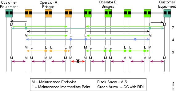
If a detected fault is due to dying gasp, the link goes down in both directions, creating AIS and RDI frame flow as shown in Figure 1.
Figure 1 AIS/RDI Frame Flow with Fault on Both rx and tx
ETH-RDI Function
The ETH-RDI function is used by a MEP to communicate to its peer MEPs that a defect condition has been encountered. ETH-RDI is used only when ETH-CC transmission is enabled.
ETH-RDI has the following two applications:
•
•
A MEP in a defect condition transmits CCMs with ETH-RDI information. A MEP that receives a CCM examines it to ensure that its maintenance association level corresponds to its configured maintenance association level and detects the RDI condition if the RDI field is set. The receiving MEP sets the RDI field in CCMs for the duration of a defect condition, and if the MEP is enabled for CCM transmission, transmits CCMs based on the configured transmission interval. When the defect condition clears, the MEP clears the RDI field in CCMs for subsequent transmissions.
In a point-to-point Ethernet connection, a MEP can clear an RDI condition when it receives the first CCM with the RDI field cleared from its peer MEP. In a multipoint Ethernet connection, a MEP cannot determine the peer MEP with the default condition and can clear an RDI condition only when it receives a CCM with the RDI field cleared from each of its peer MEPs.
The ETH-RDI function is part of continuity checking and is enabled by default. For more information about continuity checking, see the Configuring IEEE Standard-Compliant Ethernet CFM in a Service Provider Network configuration module.
How to Configure ITU-T Y.1731 Fault Management Functions
ETH-AIS and ETH-RDI both are enabled by default when CFM is configured, but each can also be manually enabled by a separate command during CFM configuration. Perform these tasks to either disable or enable the functions.
•
•
Disabling the ETH-AIS Function
Perform this task to disable the ETH-AIS function.
SUMMARY STEPS
1.
2.
3.
4.
5.
6.
7.
8.
9.
DETAILED STEPS
Enabling ETH-AIS for a Single Interface SMEP and Disabling ETH-AIS for All Other Ports
Perform this task to manually enable the ETH-AIS function.
SUMMARY STEPS
1.
2.
3.
4.
5.
6.
7.
8.
9.
10.
11.
12.
13.
14.
15.
16.
17.
DETAILED STEPSConfiguration Examples for Configuring ITU-T Y.1731 Fault Management Functions
•
•
Example: Enabling IEEE CFM on an Interface
The following example shows how to enable IEEE CFM on an interface:
!ethernet cfm domain ServiceProvider level 4mep archive-hold-time 60service MetroCustomer1 vlan 100!ethernet cfm domain OperatorA level 1mep archive-hold-time 65service MetroCustomer1OpA vlan 100!ethernet cfm enableethernet cfm traceroute cacheethernet cfm traceroute cache size 200ethernet cfm traceroute cache hold-time 60!interface gigabitethernet3/0ethernet cfm mip level 1!interface gigabitethernet4/0ethernet cfm mip level 4ethernet cfm mep level 1 mpid 102 vlan 100!ethernet cfm cc enable level 1 vlan 100ethernet cfm cc level any vlan any interval 20 loss-threshold 3Example: Enabling AIS
The following example shows how to enable AIS:!ethernet cfm domain PROVIDER_DOMAIN level 4service customer101provider evc customer101provider@101 vlan 101continuity-checkais period 1ais level 7service customer110provider evc customer110provider@110 vlan 110continuity-check!ethernet cfm ais link-status globaldisable!!interface Ethernet 0/1no ip addressethernet oam remote-loopback supportedethernet oamethernet cfm mip level 4 vlan 1,101,110ethernet cfm ais link-status!Example: Show Commands Output
The following sample output from the show ethernet cfm maintenance-point local detail command shows the settings for the local MEP:
Router# show ethernet cfm maintenance-points local detailMEP Settings:-------------MPID: 2101DomainName: PROVIDERDOMAINLevel: 4Direction: IVlan: 101Interface: Et0/1CC-Status: EnabledMAC: aabb.cc03.8410Defect Condition: AISpresentRDI: TRUEAIS-Status: EnabledAIS Period: 1000(ms)AIS Expiry Threshold: 3.5Level to transmit AIS: DefaultSuppress Alarm configuration: EnabledSuppressing Alarms: YesThe following sample output from the show ethernet cfm smep command shows the settings for a SMEP:
Router# show ethernet cfm smepSMEP Settings:--------------Interface: Ethernet0/0AIS-Status: EnabledAIS Period: 60000 (ms)Level to transmit AIS: 4Defect Condition: No DefectThe following sample output from the show ethernet cfm smep interface command shows the settings for a specific interface on a SMEP:
Router# show ethernet cfm smep interface ethernet 0/1SMEP Settings:--------------Interface: Ethernet0/1LCK-Status: EnabledLCK Period: 60000 (ms)Level to transmit LCK: DefaultAIS-Status: EnabledAIS Period: 60000 (ms)Level to transmit AIS: DefaultDefect Condition: No DefectRouter#The following sample output from the show ethernet cfm errors command shows the Ethernet CFM errors on a device:
Router# show ethernet cfm errorsLevel Vlan MPID Remote MAC Reason Service ID5 102 - aabb.cc00.ca10 Receive AIS service testThe following sample output from the show ethernet cfm maintenance-points remote detail command shows the detailed information about a specific remote MEP:
Router# show ethernet cfm maintenance-points remote detail mpid 66MAC Address: aabb.cc00.ca10Domain/Level: PROVIDERDOMAIN/4EVC: testMPID: 66 (Can ping/traceroute)Incoming Port(s): Ethernet0/2CC Lifetime(sec): 75Age of Last CC Message(sec): 8Receive RDI: TRUEFrame Loss: 0%CC Packet Statistics: 2/0 (Received/Error)R1#MAC Address: aabb.cc00.ca10Domain/Level: PROVIDERDOMAIN/4EVC: testMPID: 66 (Can ping/traceroute)Incoming Port(s): Ethernet0/2CC Lifetime(sec): 75Age of Last CC Message(sec): 8Receive RDI: TRUEFrame Loss: 0%CC Packet Statistics: 2/0 (Received/Error)Additional References
Related Documents
IEEE CFM
Configuring IEEE Standard-Compliant Ethernet CFM in a Service Provider Network
Using OAM
IEEE CFM and Y.1731 commands: complete command syntax, command mode, command history, defaults, usage guidelines, and examples
Cisco IOS commands: master list of commands with complete command syntax, command mode, command history, defaults, usage guidelines, and examples
Standards
IEEE 802.1ag
802.1ag - Connectivity Fault Management
IEEE 802.3ah
Ethernet in the First Mile
ITU-T
ITU-T Y.1731 OAM Mechanisms for Ethernet-Based Networks
MIBs
None
To locate and download MIBs for selected platforms, Cisco software releases, and feature sets, use Cisco MIB Locator found at the following URL:
RFCs
Technical Assistance
Feature Information for Configuring ITU-T Y.1731 Fault Management Functions
Table 1 lists the release history for this feature.
Use Cisco Feature Navigator to find information about platform support and software image support. Cisco Feature Navigator enables you to determine which software images support a specific software release, feature set, or platform. To access Cisco Feature Navigator, go to http://www.cisco.com/go/cfn. An account on Cisco.com is not required.
Note
Table 1 Feature Information for Configuring ITU-T Y.1731 Fault Management Functions
Configuring ITU-T Y.1731 Fault Management Functions
15.0(1)XA
12.2(33)SRE
15.1(1)TThe ITU-Y.1731 Fault Management Functions feature adds to IEEE CFM the ETH-AIS and ETH-RDI functions for fault detection, fault verification, and fault isolation in large MANs and WANs.
The following sections provide information about this feature:
•
•
•
The following commands were introduced or modified: ais, clear ethernet cfm ais, disable (CFM-AIS-link), ethernet cfm ais link-status, ethernet cfm ais link-status global, level (cfm-ais-link), period (cfm-ais-link), show ethernet cfm errors, show ethernet cfm maintenance-points local, show ethernet cfm maintenance-points remote detail, show ethernet cfm smep.
Cisco and the Cisco Logo are trademarks of Cisco Systems, Inc. and/or its affiliates in the U.S. and other countries. A listing of Cisco's trademarks can be found at www.cisco.com/go/trademarks. Third party trademarks mentioned are the property of their respective owners. The use of the word partner does not imply a partnership relationship between Cisco and any other company. (1005R)
Any Internet Protocol (IP) addresses and phone numbers used in this document are not intended to be actual addresses and phone numbers. Any examples, command display output, network topology diagrams, and other figures included in the document are shown for illustrative purposes only. Any use of actual IP addresses or phone numbers in illustrative content is unintentional and coincidental.
© 2009-2011 Cisco Systems, Inc. All rights reserved.