Feedback
Table Of Contents
Multiprotocol over ATM Overview
Multiprotocol over ATM Overview
This chapter describes the Multiprotocol over ATM (MPOA) feature, which is supported in Cisco IOS Release 11.3 and later releases.
MPOA enables the fast routing of internetwork-layer packets across a nonbroadcast multiaccess (NBMA) network. MPOA replaces multihop routing with point-to-point routing using a direct virtual channel connection (VCC) between ingress and egress edge devices or hosts. An ingress edge device or host is defined as the point at which an inbound flow enters the MPOA system; an egress edge device or host is defined as the point at which an outbound flow exits the MPOA system.
Procedures for configuring MPOA are provided in the following chapters in this publication:
•
"Configuring the Multiprotocol over ATM Client" chapter
•
•
This chapter contains the following sections:
For a complete description of the commands in this chapter, refer to the the Cisco IOS Switching Services Command Reference. To locate documentation of other commands that appear in this chapter, use the command reference master index or search online.
To identify the hardware platform or software image information associated with a feature, use the Feature Navigator on Cisco.com to search for information about the feature or refer to the software release notes for a specific release. For more information, see the section "Identifying Supported Platforms" in the chapter "Using Cisco IOS Software."
How MPOA Works
In an NBMA network, intersubnet routing involves forwarding packets hop-by-hop through intermediate routers. MPOA can increase performance and reduce latencies by identifying the edge devices, establishing a direct VCC between the ingress and egress edge devices, and forwarding Layer 3 packets directly over this shortcut VCC, bypassing the intermediate routers. An MPOA client (MPC) provides the direct VCCs between the edge devices or hosts whenever possible and forwards Layer 3 packets over these shortcut VCCs. The MPCs must be used with MPSs resident on routers.
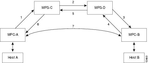
Figure 23 MPOA Message Flow Between MPCs and MPSs
The sequence of events shown in Figure 23 is summarized as follows:
1.
2.
3.
4.
5.
6.
7.
Table 18 lists and defines the MPOA terms used in Figure 23.
Traffic Flow
Figure 23 shows how MPOA messages flow from Host A to Host B. In this figure, an MPC (MPC-A) residing on a host or edge device detects a packet flow to a destination IP address (Host B) and sends an MPOA resolution request. An MPS (MPS-C) residing on a router converts the MPOA resolution request to an NHRP resolution request and passes it to the neighboring MPS/NHS (MPS-D) on the routed path. When the NHRP resolution request reaches the egress point, the MPS (MPS-D) on that router sends an MPOA cache-imposition request to MPC-B. MPC-B acknowledges the request with a cache-imposition reply and adds a tag that allows the originator of the MPOA resolution request to receive the ATM address of MPC-B. As a result, the shortcut VCC between the edge MPCs (MPC-A and MPC-B) is set up.
When traffic flows from Host A to Host B, MPC-A is the ingress MPC and MPC-B is the egress MPC. The ingress MPC contains a cache entry for Host B with the ATM address of the egress MPC. The ingress MPC switches packets destined to Host B on the shortcut VCC with the appropriate tag received in the MPOA resolution reply. Packets traversing through the shortcut VCC do not have any DLL headers. The egress MPC contains a cache entry that associates the IP address of Host B and the ATM address of the ingress MPC to a DLL header. When the egress MPC switches an IP packet through a shortcut path to Host B, it appears to have come from the egress router.
Interaction with LANE
An MPOA functional network must have at least one MPS, one or more MPCs, and zero or more intermediate routers implementing NHRP servers. The MPSs and MPCs use LANE control frames to discover each other's presence in the LANE network.
Caution
An MPC/MPS can serve as one or more LAN Emulation Clients (LECs). The LEC can be associated with any MPC/MPS in the router or Catalyst 5000 series switch. A LEC can be attached both an MPC and an MPS simultaneously.
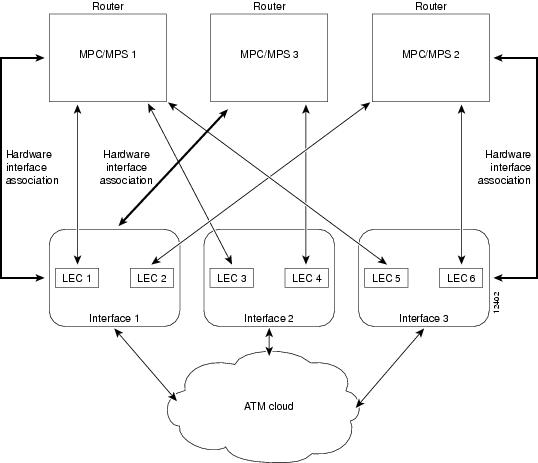
Figure 24 shows the relationships between MPC/MPS and LECs.
Figure 24 MPC-LEC and MPS-LEC Relationships
MPOA Components
The following components are required for an MPOA network:
•
•
•
•
•
An MPC identifies packets sent to an MPS, establishes a shortcut VCC to the egress MPC, and then routes these packets directly over the shortcut VCC. An MPC can be a router or a Catalyst 5000 series ATM module. An MPS can be a router or a Catalyst 5000 series Route Switch Module/Versatile Interface Processor 2 (RSM/VIP2) with an ATM interface.
Note
Benefits
MPOA provides the following benefits:
•
•
•
Configuring an MPC/MPS
To configure an MPC/MPS, perform the following tasks:
•
•
–
–
•
Multiple MPCs/MPSs can run on the same physical interface, each corresponding to different control ATM address. Once an MPC/MPS is attached to a single interface for its control traffic, it cannot be attached to another interface unless you break the first attachment. The MPC/MPS is attached to subinterface 0 of the interface.
In Figure 24, MPC/MPS 1 is attached to interface 1; MPC/MPS 1 can only use interface 1 to set up its control virtual circuits (VCs). MPC/MPS 2 is attached to interface 3; MPC/MPS 2 can only use interface 3 to set up its control VCs.
Note
More than one MPC/MPS can be attached to the same interface. MPC/MPS 3 and MPC/MPS 1 are both attached to interface 1, although they get different control addresses. Any LEC running on any subinterface of a hardware interface can be bound to any MPC/MPS. However, once a LEC is bound to a particular MPC/MPS, it cannot be bound to another MPC/MPS.
Note
Ensure that the hardware interface attached to an MPC/MPS is directly reachable through the ATM network by all the LECs that are bound to it.
Note
Any Internet Protocol (IP) addresses used in this document are not intended to be actual addresses. Any examples, command display output, and figures included in the document are shown for illustrative purposes only. Any use of actual IP addresses in illustrative content is unintentional and coincidental.
© 2007 Cisco Systems, Inc. All rights reserved.