Feedback
Table Of Contents
LANE Operation and Communication
LAN Emulation Overview
This overview chapter gives a high-level description of LAN Emulation (LANE).
Procedures for configuring LANE are provided in the following chapters in this publication:
•
"Configuring LAN Emulation" chapter
•
LAN Emulation
The Cisco implementation of LANE makes an ATM interface look like one or more Ethernet interfaces.
LANE is an ATM service defined by the ATM Forum specification LAN Emulation over ATM, ATM_FORUM 94-0035. This service emulates the following LAN-specific characteristics:
•
•
•
LANE service provides connectivity between ATM-attached devices and connectivity with LAN-attached devices. This includes connectivity between ATM-attached stations and LAN-attached stations and also connectivity between LAN-attached stations across an ATM network.
Because LANE connectivity is defined at the MAC layer, upper protocol-layer functions of LAN applications can continue unchanged when the devices join emulated LANs (ELANs). This feature protects corporate investments in legacy LAN applications.
An ATM network can support multiple independent ELAN networks. Membership of an end system in any of the ELANs is independent of the physical location of the end system. This characteristic enables easy hardware moves and location changes. In addition, the end systems can also move easily from one ELAN to another, whether or not the hardware moves.
LANE in an ATM environment provides routing between ELANs for supported routing protocols and high-speed, scalable switching of local traffic.
The ATM LANE system has three servers that are single points of failure. These are the LANE Configuration Server (LECS), the ELAN server (LES), and the broadcast and unknown server (BUS). Beginning with Cisco IOS Release 11.2, LANE fault tolerance or Simple LANE Service Replication on the ELAN provides backup servers to prevent problems if these servers fail.
The fault tolerance mechanism that eliminates these single points of failure is described in the "Configuring LAN Emulation" chapter. Although this scheme is proprietary, no new protocol additions have been made to the LANE subsystems.
LANE Components
Any number of ELANs can be set up in an ATM switch cloud. A router can participate in any number of these ELANs.
LANE is defined on a LAN client/server model. The following components are implemented:
•
Each LANE client is a member of only one ELAN. However, a router can include LANE clients for multiple ELANs: one LANE client for each ELAN of which it is a member.
If a router has clients for multiple ELANs, the Cisco IOS software can route traffic between the ELANs.
•
The Cisco implementation has a limit of one LES per ELAN.
•
In this release, the LES and the LANE BUS are combined and located in the same Cisco 7000 family or Cisco 4500 series router; one combined LECS and BUS is required per ELAN.
•
One LECS is required per LANE ATM switch cloud.
The LECS's database can have the following four types of entries:
–
–
–
–
Note
LANE Operation and Communication
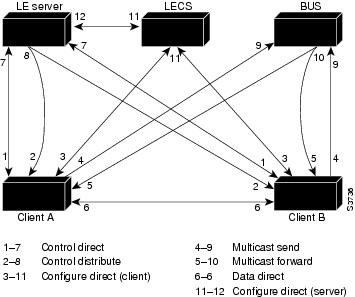
Communication among LANE components is ordinarily handled by several types of switched virtual circuits (SVCs). Some SVCs are unidirectional; others are bidirectional. Some are point-to-point and others are point-to-multipoint. Figure 12 illustrates the various virtual channel connections (VCCs)—also known as virtual circuit connections—that are used in LANE configuration.
Figure 12 shows LANE components: LE server stands for the LANE server (LECS), LECS stands for the LANE configuration server, and BUS stands for the LANE broadcast.
Figure 12 LANE VCC Types
The following section describes various processes that occur, starting with a client requesting to join an ELAN after the component routers have been configured.
Client Joining an ELAN
The following process normally occurs after a LANE client has been enabled:
•
LANE clients find the LECS by using the following methods in the listed order:
–
–
–
–
•
•
Once a Control Direct VCC is established between a LANE client and a LES, it remains up.
•
•
•
Address Resolution
As communication occurs on the ELAN, each client dynamically builds a local LANE ARP (LE ARP) table. A LE ARP table belonging to a client can also have static, preconfigured entries. The LE ARP table maps MAC addresses to ATM addresses.
Note
When a client first joins an ELAN, its LE ARP table has no dynamic entries and the client has no information about destinations on or behind its ELAN. To learn about a destination when a packet is to be sent, the client begins the following process to find the ATM address corresponding to the known MAC address:
•
•
•
•
•
•
For unknown destinations, the client sends a packet to the BUS, which forwards the packet to all clients via flooding. The BUS floods the packet because the destination might be behind a bridge that has not yet learned this particular address.
Multicast Traffic
When a LANE client has broadcast or multicast traffic, or unicast traffic with an unknown address to send, the following process occurs:
•
•
This VCC branches at each ATM switch. The switch forwards such packets to multiple outputs. (The switch does not examine the MAC addresses; it simply forwards all packets it receives.)
Typical LANE Scenarios
In typical LANE cases, one or more Cisco 7000 family routers, or Cisco 4500 series routers are attached to a Cisco LightStream ATM switch. The LightStream ATM switch provides connectivity to the broader ATM network switch cloud. The routers are configured to support one or more ELANs. One of the routers is configured to perform the LECS functions. A router is configured to perform the server function and the BUS function for each ELAN. (One router can perform the server function and the BUS function for several ELANs.) In addition to these functions, each router also acts as a LANE client for one or more ELANs.
This section presents two scenarios using the same four Cisco routers and the same Cisco LightStream ATM switch. Figure 13 illustrates a scenario in which one ELAN is set up on the switch and routers. Figure 14 illustrates a scenario in which several ELANs are set up on the switch and routers.
The physical layout and the physical components of an emulated network might not differ for the single and the multiple ELAN cases. The differences are in the software configuration for the number of ELANs and the assignment of LANE components to the different physical components.
Single ELAN Scenario
In a single ELAN scenario, the LANE components might be assigned as follows:
•
–
–
–
•
•
•
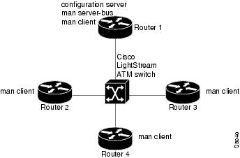
Figure 13 illustrates this single ELAN configured across several routers.
Figure 13 Single ELAN Configured on Several Routers
Multiple ELAN Scenario
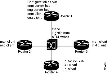
In the multiple LAN scenario, the same switch and routers are used, but multiple ELANs are configured. See Figure 14.
Figure 14 Multiple ELANs Configured on Several Routers
In the following scenario, three ELANs are configured on four routers:
•
–
–
–
–
–
•
•
•
–
–
–
In this scenario, once routing is enabled and network level addresses are assigned, Router 1 and Router 2 can route between the man and the eng ELANs, and Router 3 and Router 4 can route between the man and the mkt ELANs.
Any Internet Protocol (IP) addresses used in this document are not intended to be actual addresses. Any examples, command display output, and figures included in the document are shown for illustrative purposes only. Any use of actual IP addresses in illustrative content is unintentional and coincidental.
© 2007 Cisco Systems, Inc. All rights reserved.