Feedback
Table Of Contents
Configuring the Multiprotocol over ATM Server
Monitoring and Maintaining the MPS
Feature Information for the Multiprotocol over ATM Client
Configuring the Multiprotocol over ATM Server
First Published: October 26, 1998Last Updated: September 12, 2008The Multiprotocol over ATM (MPOA) server (MPS) supplies the forwarding information used by the MPOA clients (MPCs). The MPS responds with the information after receiving a query from a client. To support the query and response functions, MPOA has adopted the Next Hop Resolution Protocol (NHRP). The MPS on the router can also terminate shortcuts.
For a complete description of the commands in this chapter, refer to the the Cisco IOS Switching Services Command Reference. To locate documentation of other commands that appear in this chapter, use the command reference master index or search online.
To identify the hardware platform or software image information associated with a feature, use the Feature Navigator on Cisco.com to search for information about the feature or refer to the software release notes for a specific release. For more information, see the section "Identifying Supported Platforms" in the chapter "Using Cisco IOS Software."
Contents
•
Feature Information for the Multiprotocol over ATM Client
How MPS Works
The MPS software module implements the functionality of the MPS in compliance with the ATM Forum MPOA specification. The following sections describe the functions of MPS:
MPS-NHRP-Routing Interaction
MPS must interact with the NHRP module in the router to smoothly propagate MPOA/NHRP packets end to end. MPOA frames are identical to NHRP frames except for some specific op-codes and extensions for MPOA.
The following process explains the interaction of MPS and NHRP:
1.
2.
3.
Shortcut Domains
Within a router, it is possible to permit shortcuts between one group of LAN Emulation Clients (LECs) and deny it between some other groups of LECs. Cisco introduces a notion of network ID associated with an MPS. By default, all the MPSs in a router get a network ID of 1.
If the administrator wants to segregate traffic, then MPSs can be given different network IDs, in effect preventing shortcuts between LECs served by different MPSs. This can be configured in the definition of an MPS database.
If a router has both MPS and NHRP configured, then the same network ID is required to facilitate requests, replies, and shortcuts across the MPS and NHRP. The interface-specific NHRP command (ip nhrp network-id) must be the same for an MPS; otherwise, there will be a disjointed network.
MPS Configuration Task List
To configure an MPS on your network, perform the following tasks:
•
•
•
•
Configuring the ELAN ID
For MPOA to work properly, a LANE client must have an ELAN ID for all ELANs represented by the LANE clients. To configure an ELAN ID, use either of the following commands in lane database configuration mode or in interface configuration mode when starting up the LAN Emulation Client Server (LECS) for that ELAN:
Caution
Configuring the MPS
To configure an MPS, use the following commands beginning in global configuration mode. The MPS starts functioning only after it is attached to a specific hardware interface:
Configuring the MPS Variables
An MPS must be defined with a specified name before you can change the MPS variables specific to that MPS.
To change MPS variables specific only to a particular MPS, use the following commands beginning in MPS configuration mode:
Monitoring and Maintaining the MPS
To monitor and maintain the configuration of an MPS, use the following commands in EXEC mode, as needed:
MPS Configuration Example
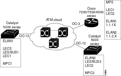
This section contains an example of the commands needed to configure an MPS. The lines beginning with exclamation points (!) are comments explaining the command shown on the following line. Figure 35 shows an example of how you can configure your system to utilize MPOA.
Figure 35 Example of an MPOA Configuration
The following example configures the MPS and attaches the MPS to a hardware interface:
! Define the MPS "MYMPS"mpoa server config name MYMPS! Leave everything as defaultexit! Enter into interface config modeinterface ATM 1/0! Attach MPS MYMPS to the HW interfacempoa server name MYMPS! Go back up to global config modeexitThe following example shows a typical MPS configuration file:
version 11.3hostname MPS! Define the MPS "mps"mpoa server config name mps! Specify the ATM interface to which the MPS is attachedinterface ATM4/0no ip addressatm pvc 1 0 5 qsaalatm pvc 2 0 16 ilmilane config auto-config-atm-addressmpoa server name mps! Specify the ATM interface that contains the LEC to which you will bind the MPSinterface ATM4/0.1 multipointip address 1.1.1.2 255.255.255.0lane client mpoa server name mpslane client ethernet elan1interface ATM4/0.2 multipointip address 1.1.2.1 255.255.255.0lane client mpoa server name mpslane client ethernet elan2endCommand Reference
The following commands are introduced or modified in the feature or features documented in this module. For information about these commands, see the Cisco IOS Asynchronous Transfer Mode Command Reference at http://www.cisco.com/en/US/docs/ios/atm/command/reference/atm_book.html. For information about all Cisco IOS commands, use the Command Lookup Tool at http://tools.cisco.com/Support/CLILookup or a Cisco IOS master commands list.
•
•
•
•
•
•
•
•
Feature Information for the Multiprotocol over ATM Client
Table 19 lists the features in this module and provides links to specific configuration information. Only features that were introduced or modified in Cisco IOS Releases 12.2(1), 12.0(3)S, 12.2(33)SRA, 12.2(33)SXH, or later releases appear in the table.
Not all commands may be available in your Cisco IOS software release. For release information about a specific command, see the command reference documentation.
Use Cisco Feature Navigator to find information about platform support and software image support. Cisco Feature Navigator enables you to determine which Cisco IOS and Catalyst OS software images support a specific software release, feature set, or platform. To access Cisco Feature Navigator, go to http://www.cisco.com/go/cfn. An account on Cisco.com is not required.
Note
Table 19 Feature Information for the Multiprotocol over ATM Client
Multiprotocol over ATM Server
12.0(1)
12.1(1)EThe Multiprotocol over ATM (MPOA) server (MPS) supplies the forwarding information used by the MPOA clients (MPCs). The MPS responds with the information after receiving a query from a client. To support the query and response functions, MPOA has adopted the Next Hop Resolution Protocol (NHRP). The MPS on the router can also terminate shortcuts.
The following sections provide information about this feature:
•
•
The following commands were introduced or modified: clear mpoa server cache, debug mpoa server, lane client mpoa server name, mpoa server config name, mpoa server name, show mpoa server, show mpoa server cache, show mpoa server statistics.
Any Internet Protocol (IP) addresses used in this document are not intended to be actual addresses. Any examples, command display output, and figures included in the document are shown for illustrative purposes only. Any use of actual IP addresses in illustrative content is unintentional and coincidental.
© 2007 Cisco Systems, Inc. All rights reserved.