Feedback
Table Of Contents
Configuring the DHCP Server On-Demand Address Pool Manager
Prerequisites for Configuring the DHCP Server On-Demand Address Pool Manager
Restrictions for Configuring the DHCP Server On-Demand Address Pool Manager
Information About the DHCP Server On-Demand Address Pool Manager
Subnet Allocation Server Operation
How to Configure the DHCP Server On-Demand Address Pool Manager
Defining DHCP ODAPs as the Global Default Mechanism
Defining DHCP ODAPs on an Interface
Configuring the DHCP Pool as an ODAP
Configuring ODAPs to Obtain Subnets Through IPCP Negotiation
Monitoring and Maintaining the ODAP
How to Configure DHCP ODAP Subnet Allocation Server Support
Configuring a Global Pool on a Subnet Allocation Server
Configuring a VRF Subnet Pool on a Subnet Allocation Server
Using a VPN ID to Configure a VRF Subnet Pool on a Subnet Allocation Server
Verifying the Subnet Allocation and DHCP Bindings
Troubleshooting the DHCP ODAP Subnet Allocation Server
Configuration Examples for DHCP Server On-Demand Address Pool Manager
Defining DHCP ODAPs as the Global Default Mechanism: Example
Defining DHCP ODAPs on an Interface: Example
Configuring the DHCP Pool as an ODAP: Example
Configuring the DHCP Pool as an ODAP for Non-MPLS VPNs: Example
IPCP Subnet Mask Delivery: Example
Configuring AAA and RADIUS: Example
Configuring a Global Pool for a Subnet Allocation Server: Example
Configuring a VRF Pool for a Subnet Allocation Server: Example
Using a VPN ID to Configure a VRF Pool on a Subnet Allocation Server: Example
Verifying Local Configuration on a Subnet Allocation Server: Example
Verifying Address Pool Allocation Information: Example
Verifying Subnet Allocation and DHCP Bindings: Example
Feature Information for the DHCP Server On-Demand Address Pool Manager
Configuring the DHCP Server On-Demand Address Pool Manager
The Cisco IOS DHCP server on-demand address pool (ODAP) manager is used to centralize the management of large pools of addresses and simplify the configuration of large networks. ODAP provides a central management point for the allocation and assignment of IP addresses. When a Cisco IOS router is configured as an ODAP manager, pools of IP addresses are dynamically increased or reduced in size depending on the address utilization level. A DHCP pool configured in the router can also be used as an IP address pooling mechanism. The IP address pooling mechanism is configured in the router to specify the source of IP addresses for PPP peers.
Module History
This module was first published on May 2, 2005, and last updated on February 27, 2006.
Finding Feature Information in This Module
Your Cisco IOS software release may not support all features. To find information about feature support and configuration, use the "Feature Information for the DHCP Server On-Demand Address Pool Manager" section.
Contents
•
Prerequisites for Configuring the DHCP Server On-Demand Address Pool Manager
•
•
•
•
•
•
Prerequisites for Configuring the DHCP Server On-Demand Address Pool Manager
Before you configure the ODAP manager, you should understand the concepts documented in the "DHCP Overview" module.
You must configure standard Multiprotocol Label Switching (MPLS) Virtual Private Networks (VPNs) unless you intend to use non-MPLS VPNs.
In order for the IP address pooling mechanism to work correctly, the VPN routing and forwarding instance (VRF) of the PPP session must match that configured on the pool. Typically this matching is done either by configuring the ip vrf forwarding vrf-name command on the virtual template interface, or if AAA is used to authorize the PPP user, it can be part of the user's profile configuration.
Restrictions for Configuring the DHCP Server On-Demand Address Pool Manager
•
•
•
•
Information About the DHCP Server On-Demand Address Pool Manager
Before you configure an ODAP, you should understand the following concepts:
•
ODAP Manager Operation
ODAPs enable pools of IP addresses to be dynamically increased or reduced in size depending on the address utilization level. Once configured, the ODAP is populated with one or more subnets leased from a source server and is ready to serve address requests from DHCP clients or from PPP sessions. The source server can be a remote DHCP server or a RADIUS server (via AAA). Currently, only the Cisco Access Registrar RADIUS server supports ODAPs. Subnets can be added to the pool when a certain utilization level (high utilization mark) is achieved. When the utilization level falls below a certain level (low utilization mark), a subnet can be returned to the server from which it was originally leased. Summarized routes for each leased subnet must be inserted or removed from the related VRF with each addition or removal of subnets into the ODAP.
ODAPs support address assignment using DHCP for customers using private addresses such as in MPLS VPNs. VPNs allow the possibility that two pools in separate networks can have the same address space, with private network addresses, served by the same DHCP server. These IP addresses can be distinguished by a VPN identifier to help select the VPN to which the client belongs.
Each ODAP is configured and associated with a particular MPLS VPN. Cisco IOS software also supports non-MPLS VPN address pools by adding pool name support to the peer default ip address dhcp-pool pool-name command.
For MPLS VPNs, each VPN is associated with one or more VRFs. The VRF is a key element in the VPN technology because it maintains the routing information that defines a customer VPN site. This customer site is attached to a provider edge (PE) router. A VRF consists of an IP routing table, a derived Cisco Express Forwarding (CEF) table, a set of interfaces that use the forwarding table, and a set of rules and routing protocol parameters that control the information that is included in the routing table.
A PPP session belonging to a specific VPN is only allocated an address from the ODAP associated with that VPN. These PPP sessions are terminated on a Virtual Home Gateway (VHG)/PE router where the ODAP is configured. The VHG/PE router maps the remote user to the corresponding MPLS VPNs.
For PPP sessions, individual address allocation from an ODAP follows a First Leased subnet First (FLF) policy. FLF searches for a free address beginning on the first leased subnet, followed by a search on the second leased subnet if no free address is available in the first subnet, and so on. This policy provides the benefit of grouping the leased addresses over time to a set of subnets, which allows an efficient subnet release and route summarization.
However, the FLF policy differs from the normal DHCP address selection policy. Normal DHCP address selection takes into account the IP address of the receiving interface or the gateway address if it is nonzero. To support both policies, the DHCP server needs to be able to distinguish between a normal DHCP address request and an address request for a PPP client. The ODAP manager uses an IP address pooling mechanism for PPP that allows the DHCP server to distinguish between a normal DHCP address request and a request from a PPP client.
Subnet release from an ODAP follows a Last Leased subnet First (LLF) policy, which prefers the last leased subnet to be released first. This LLF policy searches for a releasable subnet (a subnet with no addresses currently being leased) starting with the last leased subnet. If a releasable subnet is found (candidate subnet), it is released, and the summarized route for that subnet is removed. If more than one releasable subnet exists at that time, only the most recently allocated is released. If there are no releasable subnets, no action is taken. If by releasing the candidate subnet, the high utilization mark is reached, the subnet is not released. The first leased subnet is never released (regardless of the instantaneous utilization level) until the ODAP is disabled.
When a DHCP pool receives multiple subnets from an upstream DHCP server, an address from each subnet is automatically configured on the client connected interface so that the addresses within the subnets can be requested by DHCP clients.
The first address in the first subnet is automatically assigned to the primary address on the interface. The first address of each subsequent subnet is assigned to secondary addresses on the interface. In addition, as client addresses are reclaimed, the count of lease addresses for that subnet is decremented. Once a lease counter for a subnet reaches zero (that is, lease expiry), the subnet is returned to the pool. The previous address on the interface is removed and the first secondary address on the interface is promoted as the primary address of the interface.
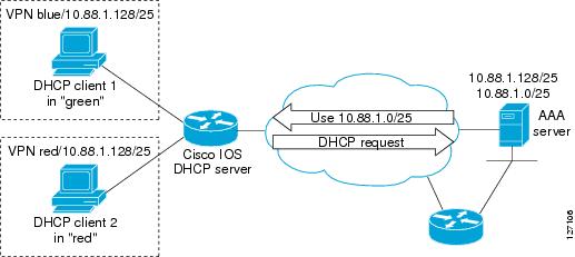
Figure 1 shows an ODAP manager configured on the Cisco IOS DHCP server. The ODAP requests an initial pool from the AAA server. Clients make DHCP requests and the DHCP server fulfills requests from the pool. When the utilization rate meets 90 percent, the ODAP manager requests an expansion and the AAA server allocates another subnet from which the ODAP manager can allocate addresses.
Figure 1 ODAP Address Pool Management for MPLS VPNs
Subnet Allocation Server Operation
You can also configure the ODAP manager to allocate subnets instead of individual IP addresses.
This capability allows the network operator to configure a Cisco IOS router as a subnet allocation server. The operation of a subnet allocation server is similar to the operation of a DHCP server, except that pools of subnets are created and assigned instead of pools of IP addresses. Subnet allocation pools are created and configured by using the subnet prefix-length command in DHCP pool configuration mode. The size of each assigned or allocated subnet is set by the prefix-length argument, using standard Common InterDomain Routing (CIDR) bit count notation to determine the number of addresses that are configured in each subnet lease.
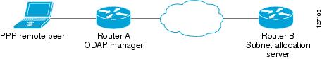
When a DHCP server is configured as a subnet allocation server, it provides subnet allocation pools for ODAP manager allocation. In Figure 2, Router B is the subnet allocation server and allocates subnets to the ODAP manager based on the demand for IP addresses and subnet availability. Router B is configured to allocate an initial amount of address space in the form of subnets to the ODAP manager. The size of the subnet allocated by the ODAP manager is determined by the subnet size that is configured on the subnet allocation server. The ODAP manager will then assign addresses to clients from these subnets and allocate more subnets as the need for address space increases.
Figure 2 Subnet Allocation Server Topology
When the ODAP manager allocates a subnet, the subnet allocation server creates a subnet binding. This binding is stored in the DHCP database for as long as the ODAP manager requires the address space. The binding is removed and the subnet is returned to the subnet pool only when the ODAP manager releases the subnet as address space utilization decreases.
The subnet allocation server can also be associated with a VRF. A VRF consists of an IP routing table, a derived CEF table, a set of interfaces that use the forwarding table, and a set of rules and routing protocol parameters that control the information that is included in the routing table.
Benefits of Using ODAPs
Efficient Address Management
The ODAP manager allows customers to optimize their use of IP addresses, thus conserving address space.
Efficient Route Summarization and Update
The ODAP manager inserts a summarized route when a subnet is added to the ODAP.
Multiple VRF and Independent Private Addressing Support
The ODAP manager automatically injects subnet routing information into the appropriate VRF.
How to Configure the DHCP Server On-Demand Address Pool Manager
This procedure contains the following tasks:
•
•
•
•
•
•
•
•
•
Defining DHCP ODAPs as the Global Default Mechanism
Perform this task to specify that the global default mechanism to use is on-demand address pooling.
IP addressing allows configuration of a global default address pooling mechanism. The DHCP server needs to be able to distinguish between a normal DHCP address request and an address request for a PPP client.
SUMMARY STEPS
1.
2.
3.
DETAILED STEPS
Defining DHCP ODAPs on an Interface
Perform this task to configure on-demand address pools on an interface.
The interface on-demand address pooling configuration overrides the global default mechanism on that interface.
SUMMARY STEPS
1.
2.
3.
4.
DETAILED STEPS
Configuring the DHCP Pool as an ODAP
Perform this task to configure a DHCP address pool as an ODAP pool.
SUMMARY STEPS
1.
2.
3.
4.
5.
6.
7.
8.
9.
DETAILED STEPS
Configuring ODAPs to Obtain Subnets Through IPCP Negotiation
Perform this task to configure your router to use subnets obtained through IP Control Protocol (IPCP) negotiation.
You can assign IP address pools to customer premises equipment (CPE) devices, which, in turn, assign IP addresses to the CPE and to a DHCP pool. This functionality has three requirements:
•
•
•
SUMMARY STEPS
1.
2.
3.
4.
5.
6.
7.
8.
DETAILED STEPS
Configuring AAA
Perform this task to configure AAA.
To allow ODAP to obtain subnets from the RADIUS server, the AAA client must be configured on the VHG/PE router.
SUMMARY STEPS
1.
2.
3.
4.
5.
or
aaa accounting network default stop-only group radius6.
DETAILED STEPS
Configuring RADIUS
Perform this task to configure RADIUS.
SUMMARY STEPS
1.
2.
3.
4.
5.
6.
7.
8.
DETAILED STEPS
Disabling ODAPs
This task shows how to disable an ODAP from a DHCP pool.
When an ODAP is disabled, all leased subnets are released. If active PPP sessions are using addresses from the released subnets, those sessions will be reset. DHCP clients leasing addresses from the released subnets will not be able to renew their leases.
SUMMARY STEPS
1.
2.
3.
4.
DETAILED STEPS
Verifying ODAP Operation
Perform this task to verify ODAP operation.
SUMMARY STEPS
1.
2.
3.
DETAILED STEPS
Step 1
Enables privileged EXEC mode. Enter your password if prompted.
Router> enableStep 2
The following output is for two DHCP pools: Green and Global. Pool Green is configured with a high utilization mark of 50 and a low utilization mark of 30. The pool is also configured to obtain more subnets when the high utilization mark is reached (autogrow). The Subnet size field indicates the values configured in the origin command as the initial and incremental subnet sizes that would be requested by the pool named Green. The Total addresses field is a count of all the usable addresses in the pool. The Leased addresses field is a total count of how many bindings were created from the pool. The Pending event field shows subnet request, which means that a subnet request is pending for the pool. The subnet request was scheduled because the Leased addresses count has exceeded the high utilization level of the pool. Subnets currently added to pool Green are shown in sequence. The Current index column shows the address that would be allocated next from this subnet. The IP address range column shows the range of usable addresses from the subnet. The Leased addresses column shows individual count of bindings created from each subnet. Three subnets are currently added to pool Green. The first two subnets have used all their addresses and thus the Current index is showing 0.0.0.0.
Notice that pool Green and pool Global can have the same subnet (172.16.0.1-172.16.0.6) because pool Green is configured to be in VRF Green, while pool Global is configured to be in the global address space.
Router# show ip dhcp poolPool Green :Utilization mark (high/low) : 50 / 30Subnet size (first/next) : 24 / 24 (autogrow)VRF name : GreenTotal addresses : 18Leased addresses : 13Pending event : subnet request3 subnets are currently in the pool :Current index IP address range Leased addresses0.0.0.0 172.16.0.1 - 172.16.0.6 60.0.0.0 172.16.0.9 - 172.16.0.14 6172.16.0.18 172.16.0.17 - 172.16.0.22 1Pool Global :Utilization mark (high/low) : 100 / 0Subnet size (first/next) : 24 / 24 (autogrow)Total addresses : 6Leased addresses : 0Pending event : none1 subnet is currently in the pool :Current index IP address range Leased addresses172.16.0.1 172.16.0.1 - 172.16.0.6 0Step 3
The following output shows the bindings from pool Green. The Type field shows On-demand, which indicates that the address binding was created for a PPP session. The Lease expiration field shows Infinite, which means that the binding is valid as long as the session is up. If a subnet must be released back to the leasing server while the session is still up, the session is reset so that it will be forced to obtain a new IP address. The Hardware address column for an On-demand entry shows the identifier for the session as detected by PPP. There are no bindings shown under the Bindings from all pools not associated with VRF field because the Global pool has not allocated any addresses.Router# show ip dhcp bindingBindings from all pools not associated with VRF:IP address Hardware address Lease expiration TypeBindings from VRF pool Green:IP address Hardware address Lease expiration Type172.16.0.1 5674.312d.7465.7374. Infinite On-demand2d38.3930.39172.16.0.2 5674.312d.7465.7374. Infinite On-demand2d38.3839.31172.16.0.3 5674.312d.7465.7374. Infinite On-demand2d36.3432.34172.16.0.4 5674.312d.7465.7374. Infinite On-demand2d38.3236.34172.16.0.5 5674.312d.7465.7374. Infinite On-demand2d34.3331.37172.16.0.6 5674.312d.7465.7374. Infinite On-demand2d37.3237.39172.16.0.9 5674.312d.7465.7374. Infinite On-demand2d39.3732.36172.16.0.10 5674.312d.7465.7374. Infinite On-demand2d31.3637172.16.0.11 5674.312d.7465.7374. Infinite On-demand2d39.3137.36172.16.0.12 5674.312d.7465.7374. Infinite On-demand2d37.3838.30172.16.0.13 5674.312d.7465.7374. Infinite On-demand2d32.3339.37172.16.0.14 5674.312d.7465.7374. Infinite On-demand2d31.3038.31172.16.0.17 5674.312d.7465.7374. Infinite On-demand2d38.3832.38172.16.0.18 5674.312d.7465.7374. Infinite On-demand2d32.3735.31
Troubleshooting Tips
By default, the Cisco IOS DHCP server on which the ODAP manager is based attempts to verify an address availability by performing a ping operation to the address before allocation. The default DHCP ping configuration will wait for 2 seconds for an ICMP echo reply. This default configuration results in the DHCP server servicing one address request every 2 seconds. The number of ping packets being sent and the ping timeout are configurable. Thus, to reduce the address allocation time, you can reduce either the timeout or the number of ping packets sent. Reducing the timeout or the ping packets being sent will improve the address allocation time, at the cost of less ability to detect duplicate addresses.
Each ODAP will make a finite number of attempts (up to four retries) to obtain a subnet from DHCP or AAA. If these attempts are not successful, the subnet request from the pool automatically starts when there is another individual address request to the pool (for example, from a newly brought up PPP session). If a pool has not been allocated any subnets, you can force restarting the subnet request process by using the clear ip dhcp pool pool-name subnet * EXEC command.
Monitoring and Maintaining the ODAP
This task shows how to monitor and maintain the ODAP.
Note the following behavior for the clear ip dhcp binding, clear ip dhcp conflict, and clear ip dhcp subnet commands:
•
•
•
•
SUMMARY STEPS
1.
2.
3.
4.
5.
6.
7.
8.
9.
DETAILED STEPS
How to Configure DHCP ODAP Subnet Allocation Server Support
This procedure contains the following tasks:
•
•
•
•
•
Configuring a Global Pool on a Subnet Allocation Server
Perform this task to configure a global subnet pool on a subnet allocation server.
Global Subnet Pools
Global subnet pools are created in a centralized network. The ODAP manager allocates subnets from the subnet allocation server based on subnet availability. When the ODAP manager allocates a subnet, the subnet allocation server creates a subnet binding. This binding is stored in the DHCP database for as long as the ODAP manager requires the address space. The binding is destroyed and the subnet is returned to the subnet pool only when the ODAP manager releases the subnet as address space utilization decreases.
SUMMARY STEPS
1.
2.
3.
4.
5.
DETAILED STEPS
Configuring a VRF Subnet Pool on a Subnet Allocation Server
This task shows how to configure a VRF subnet pool on a subnet allocation server.
VRF Subnet Pools
A subnet allocation server can be configured to assign subnets from VRF subnet allocation pools for MPLS VPN clients. VPN routes between the ODAP manager and the subnet allocation server are configured based on VRF name or VPN ID configuration. The VRF and VPN ID are configured to maintain routing information that defines customer VPN sites. The VPN customer site (or Customer Equipment [CE]) is attached to a provider edge (PE) router. The VRF is used to specify the VPN and consists of an IP routing table, a derived Cisco Express Forwarding (CEF) table, a set of interfaces that use the forwarding table, and a set of rules and routing protocol parameters that control the information that is included in the routing table.
Prerequisites
The VRF name and VPN ID can be configured on the ODAP manager and subnet allocation server prior to the configuration of the subnet allocation pool.
SUMMARY STEPS
1.
2.
3.
4.
5.
6.
DETAILED STEPS
Using a VPN ID to Configure a VRF Subnet Pool on a Subnet Allocation Server
Perform this task to configure a VRF subnet pool, using a VPN ID, on a subnet allocation server.
VRF Pools and VPN IDs
A subnet allocation server can also be configured to assign subnets from VPN subnet allocation pools based on the VPN ID of a client. The VPN ID (or Organizational Unique Identifier [OUI]) is a unique identifier assigned by the IEEE.
Prerequisites
The VRF name and VPN ID can be configured on the ODAP manager and subnet allocation server prior to the configuration of the subnet allocation pool.
SUMMARY STEPS
1.
2.
3.
4.
5.
6.
7.
8.
9.
10.
11.
DETAILED STEPS
Verifying the Subnet Allocation and DHCP Bindings
Perform this task to verify subnet allocation and DHCP bindings.
The show ip dhcp pool and show ip dhcp binding commands do not need to be issued together or even in the same session as there are differences in the information that is provided. These commands, however, can be used to display and verify subnet allocation and DHCP bindings. The show running-config | begin dhcp command is used to display the local configuration of DHCP and the configuration of the subnet prefix-length command.
SUMMARY STEPS
1.
2.
3.
4.
DETAILED STEPS
Troubleshooting the DHCP ODAP Subnet Allocation Server
Perform this task to troubleshoot the DHCP ODAP subnet allocation server.
SUMMARY STEPS
1.
2.
3.
DETAILED STEPS
Configuration Examples for DHCP Server On-Demand Address Pool Manager
This section provides the following configuration examples:
•
•
•
•
•
•
•
•
•
•
•
•
Defining DHCP ODAPs as the Global Default Mechanism: Example
The following example shows how to configure the on-demand address pooling mechanism to be used to serve an address request from a PPP client.
ip address-pool dhcp-pool!ip dhcp pool Green-poolDefining DHCP ODAPs on an Interface: Example
The following example shows how to configure an interface to retrieve an IP address from an on-demand address pool:
interface Virtual-Template1ip vrf forwarding greenip unnumbered loopback1ppp authentication chappeer default ip address dhcp-pool!Configuring the DHCP Pool as an ODAP: Example
The following example shows two ODAPs configured to obtain their subnets from an external DHCP server:
Router# show runBuilding configuration...Current configuration : 3943 bytes!version 12.2service timestamps debug uptimeservice timestamps log uptimeno service password-encryption!hostname Router!no logging consoleenable password lab!username vpn_green_net1 password 0 labusername vpn_red_net1 password 0 labip subnet-zero!ip dhcp pool green_poolvrf Greenutilization mark high 60utilization mark low 40origin dhcp subnet size initial /24 autogrow /24!ip dhcp pool red_poolvrf Redorigin dhcp!ip vrf Greenrd 200:1route-target export 200:1route-target import 200:1!ip vrf Redrd 300:1route-target export 300:1route-target import 300:1ip cefip address-pool dhcp-pool!no voice hpi capture bufferno voice hpi capture destination!interface Loopback0ip address 1.1.1.1 255.255.255.255!interface Loopback1ip vrf forwarding Greenip address 100.10.10.1 255.255.255.255!interface Loopback2ip vrf forwarding Redip address 110.10.10.1 255.255.255.255!interface ATM2/0no ip addressshutdownno atm ilmi-keepalive!interface ATM3/0no ip addressno atm ilmi-keepalive!interface Ethernet4/0ip address 10.0.105.12 255.255.255.224duplex half!interface Ethernet4/1ip address 150.10.10.1 255.255.255.0duplex half!interface Ethernet4/2ip address 120.10.10.1 255.255.255.0duplex halftag-switching ip!interface Virtual-Template1ip vrf forwarding Greenip unnumbered Loopback1ppp authentication chap!interface Virtual-Template2ip vrf forwarding Greenip unnumbered Loopback1ppp authentication chap!interface Virtual-Template3ip vrf forwarding Greenip unnumbered Loopback1ppp authentication chap!interface Virtual-Template4ip vrf forwarding Redip unnumbered Loopback2ppp authentication chap!interface Virtual-Template5ip vrf forwarding Redip unnumbered Loopback2ppp authentication chap!interface Virtual-Template6ip vrf forwarding Redip unnumbered Loopback2ppp authentication chap!router ospf 100log-adjacency-changesredistribute connectednetwork 1.1.1.1 0.0.0.0 area 0network 120.10.10.0 0.0.0.255 area 0network 150.10.10.0 0.0.0.255 area 0!router bgp 100no synchronizationbgp log-neighbor-changesneighbor 3.3.3.3 remote-as 100neighbor 3.3.3.3 update-source Loopback0!address-family ipv4 vrf Redredistribute connectedredistribute staticno auto-summaryno synchronizationnetwork 110.0.0.0exit-address-family!address-family ipv4 vrf Greenredistribute connectedredistribute staticno auto-summaryno synchronizationnetwork 100.0.0.0exit-address-family!address-family vpnv4neighbor 3.3.3.3 activateneighbor 3.3.3.3 send-community extendedexit-address-family!ip classlessip route 172.19.0.0 255.255.0.0 10.0.105.1no ip http serverip pim bidir-enable!call rsvp-sync!mgcp profile default!dial-peer cor custom!gatekeepershutdown!line con 0exec-timeout 0 0line aux 0line vty 0 4password lablogin!endConfiguring the DHCP Pool as an ODAP for Non-MPLS VPNs: Example
The following example shows how to configure an interface to retrieve an IP address from an on-demand address pool. In this example, two non-VRF ODAPs are configured. There are two virtual-templates and two DHCP address pools, usergroup1 and usergroup2. Each virtual-template interface is configured to obtain IP addresses for the peer from the associated address pool.
!ip dhcp pool usergroup1origin dhcp subnet size initial /24 autogrow /24lease 0 1!ip dhcp pool usergroup2origin dhcp subnet size initial /24 autogrow /24lease 0 1!interface virtual-template1ip unnumbered loopback1peer default ip address dhcp-pool usergroup1!interface virtual-template2ip unnumbered loopback1peer default ip address dhcp-pool usergroup2IPCP Subnet Mask Delivery: Example
The following example shows a Cisco 827 router configured to use IPCP subnet masks:
Router# show runBuilding configuration...Current configuration :1479 bytes!version 12.2no service single-slot-reload-enableno service padservice timestamps debug datetime msecservice timestamps log uptimeno service password-encryption!hostname Router!no logging bufferedlogging rate-limit console 10 except errors!username 6400-nrp2 password 0 labip subnet-zeroip dhcp smart-relay!ip dhcp pool IPPOOLTESTimport allorigin ipcp!no ip dhcp-client network-discovery!interface Ethernet0ip address pool IPPOOLTESTip verify unicast reverse-pathhold-queue 32 in!interface ATM0no ip addressatm ilmi-keepalivebundle-enabledsl operating-mode autohold-queue 224 in!interface ATM0.1 point-to-pointpvc 1/40no ilmi manageencapsulation aal5mux ppp dialerdialer pool-member 1!!interface Dialer0ip unnumbered Ethernet0ip verify unicast reverse-pathencapsulation pppdialer pool 1dialer-group 1no cdp enableppp authentication chap callinppp chap hostname Routerppp chap password 7 12150415ppp ipcp accept-addressppp ipcp dns requestppp ipcp wins requestppp ipcp mask request!ip classlessip route 0.0.0.0 0.0.0.0 Dialer0no ip http server!dialer-list 1 protocol ip permitline con 0exec-timeout 0 0transport input nonestopbits 1line vty 0 4login!scheduler max-task-time 5000endConfiguring AAA and RADIUS: Example
The following example shows one pool "Green" configured to obtain its subnets from the AAA (RADIUS) server located at IP address 172.16.1.1:
!aaa new-model!aaa authorization configuration default group radiusaaa accounting network default start-stop group radiusaaa session-id common!ip subnet-zero!ip dhcp ping packets 0!ip dhcp pool Greenvrf Greenutilization mark high 50utilization mark low 30origin aaa subnet size initial /28 autogrow /28!ip vrf Greenrd 300:1route-target export 300:1route-target import 300:1!interface Ethernet1/1ip address 172.16.1.12 255.255.255.0duplex half!interface Virtual-Template1ip vrf forwarding Greenno ip address!ip radius source-interface Ethernet1/1!!IP address of the RADIUS server hostradius-server host 172.16.1.1 auth-port 1645 acct-port 1646radius-server retransmit 3radius-server attribute 32 include-in-access-reqradius-server attribute 44 include-in-access-reqradius-server key ciscoradius-server vsa send accountingradius-server vsa send authenticationConfiguring a Global Pool for a Subnet Allocation Server: Example
The following example shows how to configure a router to be a subnet allocation server and create a global subnet allocation pool named "GLOBAL-POOL" that allocates subnets from the 10.0.0.0/24 network. The configuration of the subnet prefix-length command in this example configures the size of each subnet that is allocated from the subnet pool to support 254 host IP addresses.
ip dhcp pool GLOBAL-POOLnetwork 10.0.0.0 255.255.255.0subnet prefix-length 24!Configuring a VRF Pool for a Subnet Allocation Server: Example
The following example shows how to configure a router to be a subnet allocation server and create a VRF subnet allocation pool named "VRF-POOL" that allocates subnets from the 172.16.0.0/16 network and configures the VPN to match the VRF named "RED." The configuration of the subnet prefix-length command in this example configures the size of each subnet that is allocated from the subnet pool to support 62 host IP addresses.
ip dhcp pool VRF-POOLvrf REDnetwork 172.16.0.0 /16subnet prefix-length 26!Using a VPN ID to Configure a VRF Pool on a Subnet Allocation Server: Example
The following example shows how to configure a router to be a subnet allocation server and create a VRF subnet allocation pool named "VRF-POOL" that allocates subnets from the 192.168.0.0/24 network and configures the VRF named "RED." The VPN ID must match the unique identifier that is assigned to the client site. The route target and route distinguisher are configured in the as-number:network-number format. The route target and route distinguisher must match. The configuration of the subnet prefix-length command in this example configures the size of each subnet that is allocated from the subnet pool to support 30 host IP addresses.
ip vrf REDrd 100:1route-target both 100:1vpn id 1234:123456exitip dhcp pool VPN-POOLvrf REDnetwork 192.168.0.0 /24subnet prefix-length /27exitVerifying Local Configuration on a Subnet Allocation Server: Example
The following example is output from the show running-config command. This command can be used to verify the local configuration on a subnet allocation server. The output from this command displays the configuration of the subnet prefix-length command under the DHCP pool named "GLOBAL-POOL." The total size of the subnet allocation pool is set to 254 addresses with the network command. The configuration of the subnet prefix-length command configures this pool to allocate a subnet that will support 254 host IP addresses. Because the total pool size supports only 254 addresses, only one subnet can be allocated from this pool.
Router# show running-config | begin dhcpip dhcp pool GLOBAL-POOLnetwork 10.0.0.0 255.255.255.0subnet prefix-length 24!Verifying Address Pool Allocation Information: Example
The following examples are output from the show ip dhcp pool command. This command can be used to verify subnet allocation pool configuration on the subnet allocation server and the ODAP manager. The output from this command displays information about the address pool name, utilization level, configured subnet size, total number of addresses (from subnet), pending events, and specific subnet lease information.
The following sample output shows that the configured subnet allocation size is /24 (254 IP addresses), that there is a pending subnet allocation request, and there are no subnets in the pool:
Router> show ip dhcp pool ISP-1Pool ISP-1 :Utilization mark (high/low) :100 / 0Subnet size (first/next) :24 / 24 (autogrow)Total addresses :0Leased addresses :0Pending event :subnet request0 subnet is currently in the poolThe next example shows that the configured subnet allocation size is /24 (254 IP address), the configured VRF name is "RED", and a subnet containing 254 IP addresses has been allocated but no IP addresses have been leased from the subnet:
Router> show ip dhcp pool SUBNET-ALLOCPool SUBNET-ALLOC :Utilization mark (high/low) :100 / 0Subnet size (first/next) :24 / 24 (autogrow)VRF name :REDTotal addresses :254Leased addresses :0Pending event :none1 subnet is currently in the pool :Current index IP address range Leased addresses10.0.0.1 10.0.0.1 - 10.0.0.254 0Verifying Subnet Allocation and DHCP Bindings: Example
The following example is from the show ip dhcp binding command. This command can be used to display subnet allocation to DHCP binding mapping information. The output of this command shows the subnet lease to MAC address mapping, the lease expiration, and the lease type (subnet lease bindings are configured to be automatically created and released by default). The output that is generated for DHCP IP address assignment and subnet allocation is almost identical, except that subnet leases display an IP address followed by the subnet mask (which shows the size of the allocated subnet) in CIDR bit count notation. Bindings for individual IP address only display an IP address and are not followed by a subnet mask.
Router# show ip dhcp bindingBindings from all pools not associated with VRF:IP address Client-ID/ Lease expiration TypeHardware address/User name10.0.0.0/26 0063.6973.636f.2d64. Mar 29 2003 04:36 AM Automatic656d.6574.6572.2d47.4c4f.4241.4cAdditional References
The following sections provide references related to configuring the DHCP ODAP manager.
Related Documents
Standards
MIBs
RFCs
Technical Assistance
Glossary
AAA—authentication, authorization, and accounting. Suite of network security services that provide the primary framework through which access control can be set up on your Cisco router or access server.
Cisco Access Registrar—A RADIUS server that supports service provider deployment of access services by centralizing AAA information and simplifying provisioning and management.
client—A host trying to configure its interface (obtain an IP address) using DHCP or BOOTP protocols.
DHCP—Dynamic Host Configuration Protocol.
incremental subnet size—The desired size of the second and subsequent subnets requested for an on-demand pool.
initial subnet size—The desired size of the first subnet requested for an on-demand pool.
IPCP—IP Control Protocol. Protocol that establishes and configures IP over PPP.
MPLS—Multiprotocol Label Switching. Emerging industry standard upon which tag switching is based.
ODAP—on-demand address pool.
PE router—provider edge router.
PPP—Point-to-Point Protocol.
RADIUS— Remote Authentication Dial-In User Service. Database for authenticating modem and ISDN connections and for tracking connection time.
relay agent—A router that forwards DHCP and BOOTP messages between a server and a client on different subnets.
releasable subnet—A leased subnet that has no address leased from it.
server—DHCP or BOOTP server.
VHG—Virtual Home Gateway. A Cisco IOS software component that terminates PPP sessions. It is owned and managed by the service provider on behalf of its customer to provide access to remote users of that customers network. A single service provider device (router) can host multiple VHGs of different customers. A VHG can be dynamically brought up and down based on the access pattern of the remote users. Note that there is no single IOS feature called the VHG; it is a collection of function and features.
VHG/PE router—A device that terminates PPP sessions and maps the remote users to the corresponding MPLS VPNs.
VPN—Virtual Private Network. Enables IP traffic to use tunneling to travel securely over a public TCP/IP network.
VPN information—In this document, VPN information refers to VRF name or VPN ID.
VRF—VPN routing and forwarding instance. A VRF consists of an IP routing table, a derived forwarding table, a set of interfaces that use the forwarding table, and a set of rules and routing protocols that determine what goes into the forwarding table. In general, a VRF includes the routing information that defines a customer VPN site that is attached to a PE router. Each VPN instantiated on the PE router has its own VRF.
Note
Feature Information for the DHCP Server On-Demand Address Pool Manager
Table 1 lists the features in this module and provides links to specific configuration information. Only features that were introduced or modified in Cisco IOS Releases 12.2(1) or a later release appear in the table.
Not all commands may be available in your Cisco IOS software release. For details on when support for specific commands was introduced, see the command reference documents.
For information on a feature in this technology that is not documented here, see the "DHCP Features Roadmap".
Cisco IOS software images are specific to a Cisco IOS software release, a feature set, and a platform. Use Cisco Feature Navigator to find information about platform support and Cisco IOS software image support. Access Cisco Feature Navigator at http://www.cisco.com/go/fn. You must have an account on Cisco.com. If you do not have an account or have forgotten your username or password, click Cancel at the login dialog box and follow the instructions that appear.
Note
Table 1 Feature Information for the DHCP On-Demand Address Pool Manager
DHCP Server On-Demand Address Pool Manager for Non-MPLS VPNs
12.2(15)T
12.2(28)SB
This feature was enhanced to provide ODAP support for non-MPLS VPNs.
The following section provides information about this feature:
•
The following command was modified by this feature: peer default ip address
DHCP ODAP Server Support
12.2(15)T
12.2(28)SB
This feature introduces the capability to configure a DHCP server (or router) as a subnet allocation server. This capability allows the Cisco IOS DHCP server to be configured with a pool of subnets for lease to ODAP clients.
The following section provides information about this feature:
•
The following command was introduced by this feature: subnet prefix-length.
The following command was modified by this feature: show ip dhcp binding.
DHCP Server On-Demand Address Pool Manager
12.2(8)T
12.28(SB)
The ODAP manager is used to centralize the management of large pools of addresses and simplify the configuration of large networks. ODAP provides a central management point for the allocation and assignment of IP addresses. When a Cisco IOS router is configured as an ODAP manager, pools of IP addresses are dynamically increased or reduced in size depending on the address utilization level.
The following section provides information about this feature:
•
The following commands were introduced by this feature: aaa session-id, clear ip dhcp subnet, ip address pool, ip dhcp aaa default username, origin, show ip dhcp pool, utilization mark high, utilization mark low, vrf.
The following commands were modified by this feature: clear ip dhcp binding, clear ip dhcp conflict, ip address-pool, peer default ip address.
Any Internet Protocol (IP) addresses used in this document are not intended to be actual addresses. Any examples, command display output, and figures included in the document are shown for illustrative purposes only. Any use of actual IP addresses in illustrative content is unintentional and coincidental.
Copyright © 2006 Cisco Systems, Inc. All rights reserved.
This module first published May 2, 2005. Last updated February 27, 2006.