Feedback
Table Of Contents
Configuring Ethernet, Fast Ethernet, or Gigabit Ethernet Interfaces
Ethernet, Fast Ethernet, and Gigabit Ethernet Interface Configuration Task List
Specifying an Ethernet, Fast Ethernet, or Gigabit Ethernet Interface
Specifying an Ethernet Encapsulation Method
Specifying Full-Duplex Operation
Specifying the Media and Connector Type
Extending the 10BASE-T Capability
Configuring Fast Ethernet 100BASE-T
Configuring PA-12E/2FE Port Adapters
Configuring the 100VG-AnyLAN Port Adapter
Configuring the Cisco 7200-I/O-GE+E and Cisco 7200-I/O-2FE/E Input/Output Controllers
Cisco 7200-I/O-GE+E and Cisco 7200-I/O-2FE/E Configuration Task List
Configuring the Interface Transmission Mode
Configuring the Ethernet, Fast Ethernet, and Gigabit Ethernet Interfaces
Monitoring and Maintaining the Cisco 7200-I/O GE+E and Cisco 7200-I/O-2FE/E
Fast EtherChannel Configuration Task List
Configuring the Port-Channel Interface
Configuring the Fast Ethernet Interfaces
Configuring the Gigabit Ethernet Interfaces
Source-Route Bridging over FDDI on Cisco 4000-M, Cisco 4500-M, and Cisco 4700-M Routers
Particle-Based Switching of Source-Route Bridge Packets on Cisco 7200 Series Routers
Using Connection Management Information
Enabling FDDI Bridging Encapsulation
Enabling Full-Duplex Mode on the FDDI Interface
Setting the Token Rotation Time
Setting the Transmission Valid Timer
Controlling the Transmission Timer
Modifying the FDDI Timeout Timer
Controlling SMT Frame Processing
Enabling Duplicate Address Checking
Setting FDDI Frames per Token Limit
Controlling the FDDI SMT Message Queue Size
Preallocating Buffers for Bursty FDDI Traffic
Disabling or Enabling Automatic Receiver Polarity Reversal
Disabling or Enabling the Link Test Function
Enabling Source Address Control
Enabling SNMP Illegal Address Trap
Configuring a Token Ring Interface
Particle-Based Switching of Source-Route Bridge Packets on Cisco 7200 Series Routers
Dedicated Token Ring Port Adapter
Token Ring Interface Configuration Task List
Specifying a Token Ring Interface
Configuring PCbus Token Ring Interface Management
Enabling a Token Ring Concentrator Port
Monitoring and Maintaining the Port
LAN Interface Configuration Examples
Ethernet Encapsulation Enablement Example
Full-Duplex Enablement Operation Example
PA-12E/2FE Port Configuration Examples
PA-VG100 Port Adapter Configuration Example
Cisco 7200-I/O-GE+E and Cisco 7200-I/O-2FE/E Configuration Examples
Configuring the Gigabit Ethernet Interface on the Cisco 7200-I/O-GE+E
Configuring Autonegotiation on the Cisco 7200-I/O-2FE/E
Fast EtherChannel Configuration Examples
FDDI Frames Configuration Example
Source Address for an Ethernet Hub Port Configuration Examples
SNMP Illegal Address Trap Enablement for Hub Port Example
Configuring LAN Interfaces
Use the information in this chapter to configure LAN interfaces supported on Cisco routers and access servers.
To identify the hardware platform or software image information associated with a feature, use Cisco Feature Navigator on Cisco.com to search for information about the feature.
This chapter describes the processes for configuring LAN interfaces and includes the following sections:
•
Configuring Ethernet, Fast Ethernet, or Gigabit Ethernet Interfaces
•
•
•
For examples of configuration tasks, see the "LAN Interface Configuration Examples" section.
For hardware technical descriptions and information about installing interfaces, refer to the hardware installation and configuration publication for your product. For a complete description of the LAN interface commands used in this chapter, refer to the Cisco IOS Interface and Hardware Component Command Reference. To locate documentation of other commands that appear in this chapter, use the master commands list or search online.
Configuring Ethernet, Fast Ethernet, or Gigabit Ethernet Interfaces
Cisco supports 10-Mbps Ethernet, 100-Mbps Fast Ethernet, and 1000-Mbps Gigabit Ethernet. Support for the 10-Mbps, 100-Mbps, and 1000-Mbps Ethernet interface is supplied on various Ethernet network interface cards or systems.
Fast Ethernet NP-1FE Module Benefits
•
•
•
With the Catalyst 3000 or Catalyst 5000 system, the Fast Ethernet processor can be used to aggregate up to twelve 10-Mbps LANs and give them high-speed access to such Layer 3 routing services as providing firewalls and maintaining access lists.
Cisco 7200 Series Routers with Fast Ethernet and Gigabit Ethernet
Cisco 7200 series routers support an I/O controller with an RJ-45 interface for Fast Ethernet support and an I/O controller with both RJ-45 and GBIC interfaces for Gigabit Ethernet support.
The Cisco 7200-I/O-GE+E is an Input/Output controller that provides one Gigabit Ethernet and one Ethernet port. It is equipped with a GBIC receptacle for 1000 Mbps operation and an RJ-45 receptacle for 10-Mbps operation.
The Cisco 7200-I/O-2FE/E is an I/O controller that provides two autosensing Fast Ethernet ports and is equipped with two RJ-45 receptacles for 10/100 Mbps operation.
You can configure the Fast Ethernet port for use at 100-Mbps full-duplex or half-duplex operation (half duplex is the default). The Fast Ethernet port is equipped with either a single MII receptacle or an MII receptacle and an RJ-45 receptacle. To support this new feature, the media-type interface command has been modified. The media-type command now supports two options:
•
•
The Gigabit Ethernet interface on the Cisco 7200-I/O-GE+E operates at full duplex and cannot be configured for half-duplex mode.
Second-generation Fast Ethernet Interface Processors (FEIP2-DSW-2TX and FEIP2-DSW-2FX) are available on Cisco 7500 series routers and on Cisco 7000 series routers with the 7000 Series Route Switch Processor (RSP7000) and 7000 Series Chassis Interface (RSP7000CI). The FEIP2-DSW is a dual-port, fixed-configuration interface processor that provides two 100-Mbps Fast Ethernet (FE) interfaces. Each interface on the FEIP2-DSW supports both half-duplex and full-duplex.
Refer to the Cisco Product Catalog for specific platform and hardware compatibility information.
Use the show interfaces, show controllers mci, and show controllers cbus EXEC commands to display the Ethernet port numbers. These commands provide a report for each interface supported by the router or access server.
Use the show interfaces fastethernet command to display interface statistics, and use the show controllers fastethernet to display information about the Fast Ethernet controller chip. The output shows statistics, including information about initialization block information, transmit ring, receive ring, and errors.
Use the show interfaces gigabitethernet command to display interface statistics, and use the show controllers gigabitethernet to display the information about the Gigabit Ethernet controller chip. The output shows statistics, including information about initialization block information, transmit ring, receive ring, and errors.
For information on how to configure Fast EtherChannel, see the tasks listed in the "Configuring Fast EtherChannel" section.
Ethernet, Fast Ethernet, and Gigabit Ethernet Interface Configuration Task List
To configure features on an Ethernet, Fast Ethernet, or Gigabit Ethernet interface, perform the tasks in the following sections:
•
•
•
•
•
•
•
•
Specifying an Ethernet, Fast Ethernet, or Gigabit Ethernet Interface
To specify an Ethernet interface and enter interface configuration mode, use one of the following commands in global configuration mode.
To display the Fast Ethernet slots and ports, use the show interfaces fastethernet command. The Fast Ethernet network interface module (NIM) and the Fast Ethernet Interface Processor (FEIP) default to half-duplex mode.
Specifying an Ethernet Encapsulation Method
Currently, there are three common Ethernet encapsulation methods:
•
•
•
The encapsulation method that you use depends upon the routing protocol that you are using, the type of Ethernet media connected to the router or access server, and the routing or bridging application that you configure.
To establish Ethernet encapsulation of IP packets, use one of the following commands in interface configuration mode.
For an example of selecting Ethernet encapsulation for IP, see the "Ethernet Encapsulation Enablement Example" section.
Specifying Full-Duplex Operation
The default is half-duplex mode on the FEIP2-DSW-2FX. To enable full-duplex mode on the FEIP2-DSW-2FX (for a maximum aggregate bandwidth of 200 Mbps), use either of the following commands in interface configuration mode.
Router(config-if)# full-duplex
or
Router(config-if)# no half-duplex
Enables full-duplex on the Fast Ethernet interface of the FEIP2-DSW-2FX.
For an example of enabling full-duplex mode on Fast Ethernet, see the "Full-Duplex Enablement Operation Example" section.
Caution
The FEIP2-DSW-2TX supports half-duplex only and should not be configured for full-duplex.
Specifying the Media and Connector Type
You can specify that the Ethernet network interface module (NIM) on the Cisco 4000 series routers use either the default of an attachment unit interface (AUI) and a 15-pin connector, or 10BASE-T and an RJ-45 connector. To do so, use one of the following commands in interface configuration mode.
Router(config-if)# media-type aui
Selects a 15-pin Ethernet connector.
Router(config-if)# media-type 10baset
Selects an RJ-45 Ethernet connector.
The default media connector type is an RJ-45 or SC (fiber-optic) connector. You can specify that the interface uses either an MII connector, or an RJ-45 or SC (fiber-optic) connector (this is the default). To do so, use one of the following commands in interface configuration mode.
Note
Extending the 10BASE-T Capability
On a Cisco 4000 series or Cisco 4500 series routers, you can extend the twisted-pair 10BASE-T capability beyond the standard 100 meters by reducing the squelch (signal cutoff time). This feature applies only to the LANCE controller 10BASE-T interfaces. LANCE is the AMD controller chip for the Cisco 4000 and Cisco 4500 Ethernet interface and does not apply to the Fast Ethernet interface.
To reduce squelch, use the first command in the following table in interface configuration mode. You can later restore the squelch by using the second command.
Router(config-if)# squelch reduced
Reduces the squelch.
Router(config-if)# squelch normal
Returns squelch to normal.
Configuring Fast Ethernet 100BASE-T
You must configure the Fast Ethernet 100BASE-T interface on a Cisco AS5300 so that it can be recognized as a device on the Ethernet LAN. The Fast Ethernet interface supports 10- and 100-Mbps speeds with the 10BASE-T and 100BASE-T routers, hubs, and switches.
To configure the interface, use the following commands beginning in privileged EXEC mode.
Step 1
Router# configure terminal
Enters global configuration mode.
Step 2
Router(config)# interface fastethernet number
Enters Fast Ethernet interface configuration mode.
Step 3
Router(config-if)# ip address address subnet-mask
Assigns an IP address and subnet mask to the interface.
Step 4
Router(config-if)# speed {10 | 100 | auto}
Assigns a speed to the interface. The default is 100 Mbps.1
For relationship between duplex and speed command options, see Table 4.
Step 5
Router(config-if)# duplex {full | half | auto}
Sets up the duplex configuration on the Fast Ethernet interface. The default is half duplex.1
For relationship between duplex and speed command options, see Table 4.
1 The auto option automatically negotiates the speed on the basis of the speed and the peer router, hub, or switch media.
To use the autonegotiation capability (that is, to detect speed and duplex modes automatically), you must set both speed and duplex command to auto. Setting the speed command to auto negotiates speed only, and setting duplex command to auto negotiates duplex only. Table 4 describes the performance of the access server for different combinations of the duplex and speed command options. The specified duplex command option plus the specified speed command option produces the resulting system action.
Configuring PA-12E/2FE Port Adapters
The PA-12E/2FE Ethernet switch port adapter provides Cisco 7200 series routers with up to twelve 10-Mbps and two 10/100-Mbps switched Ethernet (10BASE-T) and Fast Ethernet (100BASE-TX) interfaces for an aggregate bandwidth of 435 Mbps, full-duplex. The PA-12E/2FE port adapter supports the Ethernet, IEEE 802.3, and IEEE 802.3u specifications for 10-Mbps and 100-Mbps transmission over unshielded twisted pair (UTP) cables.
The PA-12E/2FE port adapter offloads Layer 2 switching from the host CPU by using store-and-forward or cut-through switching technology between interfaces within the same virtual LAN (VLAN) on the PA-12E/2FE port adapter. The PA-12E/2FE port adapter supports up to four VLANs (bridge groups).
Note
All interfaces on the PA-12E/2FE port adapter support autosensing and autonegotiation of the proper transmission mode (half-duplex or full-duplex) with an attached device. The first two PA-12E/2FE interfaces (port 0 and port 1) also support autosensing and autonegotiation of the proper connection speed (10 Mbps or 100 Mbps) with an attached device. If an attached device does not support autosensing and autonegotiation of the proper transmission mode, the PA-12E/2FE interfaces attached to the device automatically enter half-duplex mode. Use the show system:running-config command to determine if a PA-12E/2FE interface is autosensing and autonegotiating the proper transmission mode with an attached device. Use the full-duplex and the half-duplex commands to change the transmission mode of a PA-12E/2FE interface. After changing the transmission mode, use the show interfaces command to verify the transmission mode of the interface.
Note
To configure the PA-12E/2FE port adapter, perform the tasks in the following sections. Each task in the list is identified as either required or optional.
•
•
•
Note
For information on other commands that can be used to configure a PA-12E/2FE port adapter, refer to the Cisco IOS Interface and Hardware Component Command Reference. For information on bridging, refer to the "Configuring Transparent Bridging" chapter in the Cisco IOS Bridging and IBM Networking Configuration Guide.
For PA-12E/2FE port adapter configuration examples, see the "PA-12E/2FE Port Configuration Examples" section.
Configuring the PA-12E/2FE Port Adapter
This section provides instructions for a basic configuration. You might also need to enter other configuration commands depending on the requirements for your system configuration and the protocols that you plan to route on the interface. For complete descriptions of configuration commands and the configuration options available, refer to the other configuration guides and command references in the Cisco IOS documentation set.
To configure the interfaces on the PA-12E/2FE port adapter, use the following commands beginning in global configuration mode.
To enable integrated routing and bridging on the bridge groups, use the following commands beginning in global configuration mode.
Monitoring and Maintaining the PA-12E/2FE Port Adapter
After configuring the new interface, you can display its status and verify other information. To display information about the PA-12E/2FE port adapter, use the following commands in EXEC mode.
Configuring Bridge Groups Using the 12E/2FE VLAN Configuration WebTool
The 12E/2FE VLAN Configuration WebTool, shown in Figure 3, is a web browser-based Java applet that displays configured interfaces and bridge groups for PA-12E/2FE port adapters installed in Cisco routers. With the WebTool you can perform the following tasks:
•
•
•
•
•
You can access the 12E/2FE VLAN Configuration WebTool from the home page of your router. For complete procedures on how to use the VLAN Configuration WebTool, refer to the PA-12E/2FE Ethernet Switch Port Adapter book that accompanies the hardware.
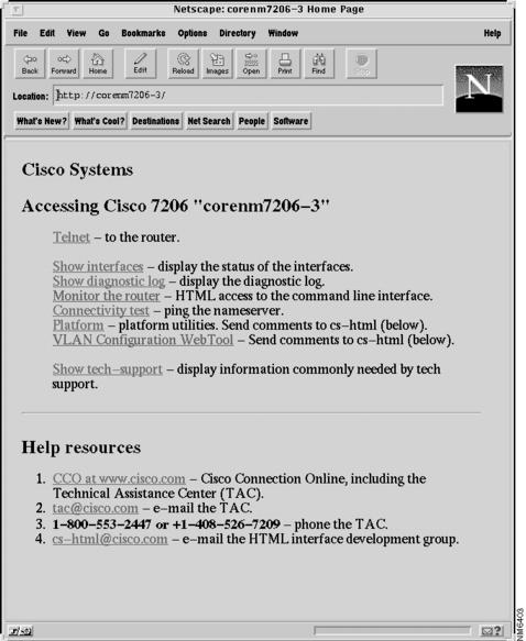
Figure 3 Example Home Page for a Cisco 7200 Series Router (Cisco 7206 Shown)
All Cisco routers that run Cisco IOS Release 11.0 or later have a home page. All Cisco router home pages are password protected. Contact your network administrator if you do not have the name or password for your Cisco 7200 series router.
If your router has an installed PA-12E/2FE port adapter, the 12E/2FE VLAN Configuration WebTool shown in Figure 3 can be accessed from the home page of the router using a Java-enabled web browser.
Configuring the 100VG-AnyLAN Port Adapter
The 100VG-AnyLAN port adapter (PA-100VG) is available on Cisco 7200 series routers and on Cisco 7500 series routers.
The PA-100VG provides a single interface compatible with and specified by IEEE 802.12 to support 100 Mbps over Category 3 or Category 5 UTP cable with RJ-45 terminators. The PA-100VG supports 802.3 Ethernet packets and can be monitored with the IEEE 802.12 Interface MIB.
To configure the PA-100VG port adapter, use the following commands beginning in global configuration mode.
Note
Configuring the PA-100VG interface is similar to configuring an Ethernet or Fast Ethernet interface. To display information about the 100VG-AnyLAN port adapter, use the show interfaces vg-anylan EXEC command.
Configuring the Cisco 7200-I/O-GE+E and Cisco 7200-I/O-2FE/E Input/Output Controllers
The Cisco 7200-I/O-GE+E is an Input/Output controller that provides one Gigabit Ethernet and one Ethernet port. It is equipped with a GBIC receptacle for 1000-Mbps operation and an RJ-45 receptacle for 10-Mbps operation.
The Cisco 7200-I/O-2FE/E is an Input/Output controller that provides two autosensing Fast Ethernet ports and is equipped with two RJ-45 receptacles for 10/100-Mbps operation.
I/O controllers support the following features:
•
•
•
•
•
Cisco 7200-I/O-GE+E and Cisco 7200-I/O-2FE/E Configuration Task List
See the following sections for configuration tasks for the Cisco 7200-I/O-GE+E and the Cisco 7200-I/O-2FE/E feature. Each task in the list is identified as required or optional.
•
•
•
•
•
Note
Configuring the Interface Transmission Mode
To configure the interface transmission mode, use the following commands beginning in privileged EXEC mode. The Fast Ethernet and Ethernet interfaces on the Cisco 7200-I/O-2FE/E are duplex auto by default.
Step 1
Enters global configuration mode and specifies that the console terminal is the source of the configuration subcommands.
Step 2
Selects the Fast Ethernet interface to configure.
Step 3
Changes the Fast Ethernet interface port transmission mode to full duplex from autonegotiation.
1 Use the interface fastethernet router-shelf/slot/port command for a Cisco 7200 VXR used as a router shelf in an AS5800 Universal Access Server.
Configuring Interface Speed
To configure the two autosensing Ethernet/Fast Ethernet interfaces on the C7200-I/O-2FE/E, use the speed command. The the default interface speed is auto. The following procedure configures the C7200-I/O-2FE/E for a speed of 10 Mbps.
Step 1
Enters global configuration mode and specifies that the console terminal is the source of the configuration subcommands.
Step 2
Selects the Ethernet interface to configure.
Selects the Fast Ethernet interface to configure.
Step 3
Sets the Ethernet or Fast Ethernet interface speed to 10 Mbps.
1 Use the interface ethernet router-shelf/slot/port command for a Cisco 7200 VXR used as a router shelf in an AS5800 Universal Access Server.
2 Use the interface fastethernet router-shelf/slot/port command for a Cisco 7200 VXR used as a router shelf in an AS5800 Universal Access Server.
Configuring the Ethernet, Fast Ethernet, and Gigabit Ethernet Interfaces
The following procedure explains a basic configuration for an Ethernet, Fast Ethernet, or Gigabit Ethernet interface on a C7200-I/O-GE+E or a C7200-I/O-2FE/E.
Step 1
Enters global configuration mode and specifies that the console terminal is the source of the configuration subcommands.
Step 2
Selects the Ethernet interface on the I/O controller in slot 0 in port adapter slot 1 to configure.
Selects the Fast Ethernet interface on the I/O controller in slot 0 in port adapter slot 2 to configure.
Selects the Gigabit Ethernet interface on the I/O controller in slot 0 in port adapter slot 0 to configure.
Step 3
Assigns an IP address and subnet mask to the interface (if IP routing is enabled on the system).
Step 4
Changes the Fast Ethernet interface port transmission mode to autonegotiation.
Step 5
Router#(config-if)# Ctrl-ZExits configuration mode.
1 Use the interface ethernet router-shelf/slot/port command for a Cisco 7200 VXR used as a router shelf in an AS5800 Universal Access Server.
2 Use the interface fastethernet router-shelf/slot/port command for a Cisco 7200 VXR used as a router shelf in an AS5800 Universal Access Server.
3 Use the interface gigabitethernet router-shelf/slot/port command for a Cisco 7200 VXR used as a router shelf in an AS5800 Universal Access Server.
Verifying the Configuration
Use the show interfaces {ethernet | fastethernet | gigabitethernet} command to verify that the interface and line protocol are in the correct state (up) and that the transmission mode is configured on the interface. You can configure full, half, or auto transmission mode for Ethernet and Fast Ethernet interfaces. You can configure forced transmission mode for Gigabit Ethernet interfaces. The following is sample output from the show interfaces gigabitethernet command.
Router# show interfaces gigabitethernet 0/0GigabitEthernet0/0 is up, line protocol is upHardware is 82543 (Livengood), address is 00d0.ffb6.4c00 (bia 00d0.ffb6.4c00)Internet address is 10.1.1.0/0MTU 1500 bytes, BW 1000000 Kbit, DLY 10 usec,reliability 255/255, txload 1/255, rxload 1/255Encapsulation ARPA, loopback not setKeepalive set (10 sec)Full-duplex mode, link type is autonegotiation, media type is SXoutput flow-control is on, input flow-control is onARP type:ARPA, ARP Timeout 04:00:00Last input 00:00:04, output 00:00:03, output hang neverLast clearing of "show interface" counters neverQueueing strategy:fifoOutput queue 0/40, 0 drops; input queue 0/75, 0 drops5 minute input rate 0 bits/sec, 0 packets/sec5 minute output rate 0 bits/sec, 0 packets/sec2252 packets input, 135120 bytes, 0 no bufferReceived 2252 broadcasts, 0 runts, 0 giants, 0 throttles0 input errors, 0 CRC, 0 frame, 0 overrun, 0 ignored0 watchdog, 0 multicast, 0 pause input0 input packets with dribble condition detected2631 packets output, 268395 bytes, 0 underruns0 output errors, 0 collisions, 2 interface resets0 babbles, 0 late collision, 0 deferred0 lost carrier, 0 no carrier, 0 pause output0 output buffer failures, 0 output buffers swapped outMonitoring and Maintaining the Cisco 7200-I/O GE+E and Cisco 7200-I/O-2FE/E
To monitor and maintain the Gigabit Ethernet or Ethernet interfaces on the Cisco 7200-I/O-GE+E, use the following commands in privileged EXEC mode.
Displays hardware and software information about the Ethernet interface.
Displays information about the Ethernet interface on the router.
Displays hardware and software information about the Gigabit Ethernet interface.
Displays information about a Gigabit Ethernet interface on the router.
1 Use the show interfaces ethernet router-shelf/slot/port command for a Cisco 7200 VXR used as a router shelf in an AS5800 Universal Access Server
2 Use the interface gigabitethernet router-shelf/slot/port command for a Cisco 7200 VXR used as a router shelf in an AS5800 Universal Access Server.
To monitor and maintain the Fast Ethernet or Ethernet interfaces on the Cisco 7200-I/O-2FE/E, use the following commands in privileged EXEC mode.
Displays hardware and software information about the Ethernet interface.
Displays information about an Ethernet interface on the router.
Displays hardware and software information about the Fast Ethernet interfaces.
Displays information about a Fast Ethernet interface on the router.
1 Use the show interfaces ethernet router-shelf/slot/port command for a Cisco 7200 VXR used as a router shelf in an AS5800 Universal Access Server.
Configuring Fast EtherChannel
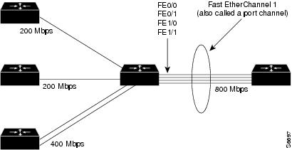
The Fast EtherChannel feature allows multiple Fast Ethernet point-to-point links to be bundled into one logical link to provide bidirectional bandwidth of up to 800 Mbps. Fast EtherChannel builds on standards-based 802.3 full-duplex Fast Ethernet to provide fault-tolerant, high-speed links between switches, routers, and servers. This feature can be configured between Cisco 7200 series routers, Cisco 7500 series routers, and Cisco 7000 series routers with the 7000 Series Route Switch Processor (RSP7000) and 7000 Series Chassis Interface (RSP7000CI) or between a Cisco 7500 series router or a Cisco 7000 series router with the RSP7000 and RSP7000CI and a Catalyst 5000 switch.
Note
Fast EtherChannel provides higher bidirectional bandwidth, redundancy, and load sharing. Up to four Fast Ethernet interfaces can be bundled in a port channel, and the router or switch can support up to four port channels. The Fast EtherChannel feature is capable of load balancing traffic across the Fast Ethernet links. Unicast, broadcast, and multicast traffic is distributed across the links providing higher performance and redundant parallel paths. In the event of a link failure, traffic is redirected to remaining links within the Fast EtherChannel without user intervention.
Fast EtherChannel feature, IP traffic is distributed over the port channel interface while traffic from other routing protocols is sent over a single link. Bridged traffic is distributed on the basis of the Layer 3 information in the packet. If the Layer 3 information does not exist in the packet, the traffic is sent over the first link.
Fast EtherChannel supports all features currently supported on the Fast Ethernet interface. You must configure these features on the port-channel interface rather than on the individual Fast Ethernet interfaces. Fast EtherChannel connections are fully compatible with Cisco IOS VLAN and routing technologies. The Inter-Switch Link (ISL) VLAN trunking protocol can carry multiple VLANs across a Fast EtherChannel, and routers attached to Fast EtherChannel links can provide full multiprotocol routing with support for host standby using Hot Standby Router Protocol (HSRP).
The port channel (consisting of up to four Fast Ethernet interfaces) is treated as a single interface. A port channel is used in the Cisco IOS software to maintain compatibility with existing commands on the Catalyst 5000 switch. You create the Fast EtherChannel by using the interface port-channel interface configuration command. You can assign up to four Fast Ethernet interfaces to a port channel by using the channel-group interface configuration command.
Additional Fast EtherChannel features include
•
For more information about configuring HSRP, refer to the "Configuring IP Services" chapter in the Cisco IOS IP Application Services Configuration Guide.
•
For more information about configuring CEF, refer to the "Configuring Cisco Express Forwarding" part of the Cisco IOS IP Switching Configuration Guide.
For information on how to configure Ethernet or Fast Ethernet, see the tasks listed in the "Configuring the Ethernet, Fast Ethernet, and Gigabit Ethernet Interfaces" section.
Fast EtherChannel Configuration Task List
To configure Fast EtherChannel, perform the tasks in the following sections. Each task is identified as required or optional.
•
•
For information on other commands that can be used by the Fast EtherChannel, refer to the other configuration guides and command references in the Cisco IOS documentation set.
Configuring the Port-Channel Interface
To configure the port-channel interface, use the following commands beginning in global configuration mode.
Note
Caution
Configuring the Fast Ethernet Interfaces
To assign the Fast Ethernet interfaces to the Fast EtherChannel, use the following commands beginning in global configuration mode.
Caution
To remove a Fast Ethernet interface from a Fast EtherChannel, use the following commands beginning in global configuration mode.
The Cisco IOS software automatically removes a Fast Ethernet interface from the Fast EtherChannel if the interface goes down, and the software automatically adds the Fast Ethernet interface to the Fast EtherChannel when the interface is back up.
Currently, Fast EtherChannel relies on keepalives to detect whether the line protocol is up or down. Keepalives are enabled by default on the Fast Ethernet interfaces. If the line protocol on the interface goes down because it did not receive a keepalive signal, the Fast EtherChannel detects that the line protocol is down and removes the interface from the Fast EtherChannel. However, if the line protocol remains up because keepalives are disabled on the Fast Ethernet interface, the Fast EtherChannel cannot detect this link failure (other than a cable disconnect) and does not remove the interface from the Fast EtherChannel even if the line protocol goes down. This can result in unpredictable behavior. The implementation of the Port Aggregation Protocol in a subsequent release of this feature will remove the dependency on keepalives.
See the "LAN Interface Configuration Examples" section for configuration examples.
You can monitor the status of the Fast EtherChannel interface by using the show interfaces port-channel EXEC command.
Configuring the Gigabit Ethernet Interfaces
To assign the Gigabit Ethernet interfaces to the Gigabit EtherChannel, use the following commands beginning in global configuration mode.
To remove a Gigabit Ethernet interface from a Gigabit EtherChannel, use the following commands beginning in global configuration mode.
You can monitor the status of the Gigabit EtherChannel interface by using the show interfaces port-channel EXEC command.
Configuring a FDDI Interface
The FDDI is an ANSI-defined standard for timed 100-Mbps token passing over fiber-optic cable. FDDI is not supported on access servers.
A FDDI network consists of two counter-rotating, token-passing fiber-optic rings. On most networks, the primary ring is used for data communication and the secondary ring is used as a hot standby. The FDDI standard sets a total fiber length of 200 kilometers. (The maximum circumference of the FDDI network is only half the specified kilometers because of the wrapping or looping back of the signal that occurs during fault isolation.)
The FDDI standard allows a maximum of 500 stations with a maximum distance between active stations of 2 kilometers when interconnecting them with multimode fiber or 10 kilometers when interconnected via single mode fiber, both of which are supported by our FDDI interface controllers. The FDDI frame can contain a minimum of 17 bytes and a maximum of 4500 bytes. Our implementation of FDDI supports Station Management (SMT) Version 7.3 of the X3T9.5 FDDI specification, offering a single MAC dual-attach interface that supports the fault-recovery methods of the dual attachment stations (DASs). The mid-range platforms also support single attachment stations (SASs).
Refer to the Cisco Product Catalog for specific information on platform and interface compatibility. For installation and configuration information, refer to the installation and configuration publication for the appropriate interface card or port adapter.
Source-Route Bridging over FDDI on Cisco 4000-M, Cisco 4500-M, and Cisco 4700-M Routers
Source-route bridging (SRB) is supported on the FDDI interface to the Cisco 4000-M, Cisco 4500-M, and Cisco 4700-M routers. For instructions on configuring autonomous FDDI SRB or fast-switching SRB over FDDI, refer to the "Configuring Source-Route Bridging" chapter of the Cisco IOS Bridging and IBM Networking Configuration Guide.
Particle-Based Switching of Source-Route Bridge Packets on Cisco 7200 Series Routers
SRB is supported over FDDI. Particle-based switching is supported for SRB packets (over FDDI and Token Ring) by default.
Particle-based switching adds scatter-gather capability to SRB to improve performance. Particles represent a communications data packet as a collection of noncontiguous buffers. The traditional Cisco IOS packet has a packet type control structure and a single contiguous data buffer. A particle packet has the same packet type control structure, but also maintains a queue of particle type structures, each of which manages its own block.
The scatter-gather architecture used by particle-based switching provides the following advantages:
•
•
•
For information about configuring SRB over FDDI, refer to the "Configuring Source-Route Bridging" chapter of the Cisco IOS Bridging and IBM Networking Configuration Guide.
Using Connection Management Information
Connection management (CMT) is a FDDI process that handles the transition of the ring through its various states (off, on, active, connect, and so on) as defined by the X3T9.5 specification. The FIP (FDDI Interface Processor) provides CMT functions in microcode.
A partial sample output of the show interfaces fddi command follows, along with an explanation of how to interpret the CMT information in the output.
Phy-A state is active, neighbor is B, cmt signal bits 08/20C, status ALSPhy-B state is active, neighbor is A, cmt signal bits 20C/08, status ILSCFM is thru A, token rotation 5000 usec, ring operational 0:01:42Upstream neighbor 0800.2008.C52E, downstream neighbor 0800.2008.C52EThe show interfaces fddi example shows that Physical A (Phy-A) completed CMT with its neighbor. The state is active, and the display indicates a Physical B-type neighbor.
The sample output indicates CMT signal bits 08/20C for Phy-A. The transmit signal bits are 08. Looking at the pulse code modulation (PCM) state machine, 08 indicates that the port type is A, that the port compatibility is set, and that the LCT duration requested is short. The receive signal bits are 20C, that indicate that the neighbor type is B, that port compatibility is set, that there is a MAC on the port output, and so on.
The neighbor is determined from the received signal bits, as follows:
Interpreting the bits in the diagram above, the received value equals 0x20C. Bit positions 1 and 2 (0 1) indicate a Physical B-type connection.
The transition states displayed indicate that the CMT process is running and actively trying to establish a connection to the remote physical connection. The CMT process requires state transition with different signals being transmitted and received before moving on to the state ahead as indicated in the PCM state machine. The 10 bits of CMT information are transmitted and received in the Signal State. The NEXT state is used to separate the signaling performed in the Signal State. Therefore, in the preceding sample output, the NEXT state was entered 11 times.
Note
The CFM state is through A in the sample output, which means the Phy-A of this interface has successfully completed CMT with the Phy-B of the neighbor and Phy-B of this interface has successfully completed CMT with the Phy-A of the neighbor.
The display (or nondisplay) of the upstream and downstream neighbor does not affect the ability to route data. Because the upstream neighbor is also its downstream neighbor in the sample, there are only two stations in the ring: the network server and the router at address 0800.2008.C52E.
FDDI Configuration Task List
To configure a FDDI interface, perform the tasks in the following sections. Each task in the list is identified as either required or optional.
•
•
•
•
•
•
•
•
•
•
•
•
•
•
•
•
•
Specifying a FDDI Interface
To specify a FDDI interface and enter interface configuration mode, use one of the following commands in global configuration mode.
Enabling FDDI Bridging Encapsulation
By default, Cisco FDDI uses the SNAP encapsulation format defined in RFC 1042. It is not necessary to define an encapsulation method for this interface when using the FIP.
FIP fully supports transparent and translational bridging for the following configurations:
•
•
•
Enabling FDDI bridging encapsulation places the FIP into encapsulation mode when doing bridging. In transparent mode, the FIP interoperates with earlier versions of encapsulating interfaces when performing bridging functions on the same ring. When using the FIP, you can specify the encapsulation method by using the following command in interface configuration mode.
Router(config-if)# fddi encapsulate
Specifies the encapsulation method for the FIP.
When you are doing translational bridging, use routing for routable protocols and use translational bridging for the rest, such as local-area transport (LAT).
Note
We are currently aware of problems with the following protocols when bridged between Token Ring and other media: AppleTalk, DECnet, IP, Novell IPX, Phase IV, VINES, and XNS. Further, the following protocols might have problems when bridged between FDDI and other media: Novell IPX and XNS. We recommend that these protocols be routed whenever possible.
Enabling Full-Duplex Mode on the FDDI Interface
To enable full-duplex mode on the PA-F/FD-SM and PA-F/FD-MM port adapters, use one of the following commands in interface configuration mode.
Router(config-if)# full-duplex
or
Router(config-if)# no half-duplex
Enables full-duplex on the FDDI interface of the PA-F/FD-SM and PA-F/FD-MM port adapter.
Setting the Token Rotation Time
You can set the FDDI token rotation time to control ring scheduling during normal operation and to detect and recover from serious ring error situations. To do so, use the following command in interface configuration mode.
Router(config-if)# fddi token-rotation-time microseconds
Sets the FDDI token rotation time.
The FDDI standard restricts the allowed time to greater than 4000 microseconds and less than 165,000 microseconds. As defined in the X3T9.5 specification, the value remaining in the token rotation timer (TRT) is loaded into the token holding timer (THT). Combining the values of these two timers provides the means to determine the amount of bandwidth available for subsequent transmissions.
Setting the Transmission Valid Timer
You can set the transmission timer to recover from a transient ring error by using the following command in interface configuration mode.
Router(config-if)# fddi valid-transmission-time microseconds
Sets the FDDI valid transmission timer.
Controlling the Transmission Timer
You can set the FDDI control transmission timer to control the FDDI TL-Min time, which is the minimum time to transmit a Physical Sublayer or PHY line state before advancing to the next Physical Connection Management or PCM state as defined by the X3T9.5 specification. To do so, use the following command in interface configuration mode.
Router(config-if)# fddi tl-min-time microseconds
Sets the FDDI control transmission timer.
Modifying the C-Min Timer
You can modify the C-Min timer on the PCM from its default value of 1600 microseconds by using the following command in interface configuration mode.
Router(config-if)# fddi c-min microseconds
Sets the C-Min timer on the PCM.
Modifying the TB-Min Timer
You can change the TB-Min timer in the PCM from its default value of 100 milliseconds. To do so, use the following command in interface configuration mode.
Modifying the FDDI Timeout Timer
You can change the FDDI timeout timer in the PCM from its default value of 100 ms. To do so, use the following command in interface configuration mode.
Router(config-if)# fddi t-out milliseconds
Sets the timeout timer in the PCM.
Controlling SMT Frame Processing
You can disable and enable SMT frame processing for diagnostic purposes. To do so, use one of the following commands in interface configuration mode.
Router(config-if)# no fddi smt-frames
Disables SMT frame processing.
Router(config-if)# fddi smt-frames
Enables SMT frame processing.
Enabling Duplicate Address Checking
You can enable the duplicate address detection capability on the FDDI. If the FDDI finds a duplicate address, it displays an error message and shuts down the interface. To enable duplicate address checking, use the following command in interface configuration mode.
Router(config-if)# fddi duplicate-address-check
Enables duplicate address checking capability.
Setting the Bit Control
You can set the FDDI bit control to control the information transmitted during the Connection Management (CMT) signaling phase. To do so, use the following command in interface configuration mode.
Router(config-if)# fddi cmt-signal-bits signal-bits [phy-a | phy-b]
Sets the FDDI bit control.
Controlling the CMT Microcode
You can control whether the CMT onboard functions are on or off. The FIP provides CMT functions in microcode. These functions are separate from those provided on the processor card and are accessed through EXEC commands.
The default is for the FIP CMT functions to be on. A typical reason to disable these functions is when you work with new FDDI equipment and have problems bringing up the ring. If you disable the CMT microcode, the following actions occur:
•
•
To disable the CMT microcode, use the following command in interface configuration mode.
Starting and Stopping FDDI
In normal operation, the FDDI interface is operational once the interface is connected and configured. You can start and stop the processes that perform the CMT function and allow the ring on one fiber to be stopped. To do so, use either of the following commands in EXEC mode.
Do not use either of the preceding commands during normal operation of FDDI; they are used during interoperability tests.
Setting FDDI Frames per Token Limit
The FDDI interface is able to transmit multiple frames per token on a Cisco 4000, a Cisco 4500, and a Cisco 4700 series router, instead of transmitting only a single frame at a time. You can specify the maximum number of frames to be transmitted with each token capture. This significantly improves your throughput when you have heavy or very bursty traffic.
To configure the FDDI interface to transmit a maximum number of frames per token capture, use the following commands beginning in privileged EXEC mode.
Controlling the FDDI SMT Message Queue Size
You can set the maximum number of unprocessed FDDI Station Management (SMT) frames that will be held for processing. Setting this number is useful if the router that you are configuring gets bursts of messages that arrive faster than the router can process. To set the number of frames, use the following command in global configuration mode.
Preallocating Buffers for Bursty FDDI Traffic
The FCI card preallocates three buffers to handle bursty FDDI traffic (for example, Network File System (NFS) bursty traffic). You can change the number of preallocated buffers use the following command in interface configuration mode.
Router(config-if)# fddi burst-count
Preallocates buffers to handle bursty FDDI traffic.
Configuring a Hub Interface
Cisco 2500 series includes routers that have hub functionality for an Ethernet interface. The hub is a multiport repeater. The advantage of an Ethernet interface over a hub is that the hub provides a star-wiring physical network configuration while the Ethernet interface provides 10BASE-T physical network configuration. The router models with hub ports and their configurations are as follows:
•
•
•
Cisco provides Simple Network Management Protocol (SNMP) management of the Ethernet hub as specified in RFC 1516, Definitions of Managed Objects for IEEE 802.3 Repeater Devices.
To configure hub functionality on an Ethernet interface, perform the tasks in the following sections Each task in the list is identified as either required or optional.
•
•
•
•
•
For configuration examples, see the "Hub Configuration Examples" section.
Enabling a Hub Port
To enable a hub port, use the following commands in global configuration mode.
Disabling or Enabling Automatic Receiver Polarity Reversal
On Ethernet hub ports only, the hub ports can invert, or correct, the polarity of the received data if the port detects that the received data packet waveform polarity is reversed because of a wiring error. This receive circuitry polarity correction allows the hub to repeat subsequent packets with correct polarity. When enabled, this function is executed once after reset of a link fail state.
Automatic receiver polarity reversal is enabled by default. To disable this feature on a per-port basis, use the following command in hub configuration mode.
Router(config-hub)# no auto-polarity
Disables automatic receiver polarity reversal.
To enable automatic receiver polarity reversal on a per-port basis, use the following command in hub configuration mode.
Router(config-hub)# auto-polarity
Enables automatic receiver polarity reversal.
Disabling or Enabling the Link Test Function
The link test function applies to Ethernet hub ports only. The Ethernet ports implement the link test function as specified in the 802.3 10BASE-T standard. The hub ports will transmit link test pulses to any attached twisted pair device if the port has been inactive for more than 8 to 17 milliseconds.
If a hub port does not receive any data packets or link test pulses for more than 65 to 132 milliseconds and the link test function is enabled for that port, that port enters link fail state and cannot transmit or receive. The hub port is enabled again when it receives four consecutive link test pulses or a data packet.
The link test function is enabled by default. To allow the hub to interoperate with 10BASE-T twisted-pair networks that do not implement the link test function, the link test receive function of the hub can be disabled on a per-port basis. To do so, use the following command in hub configuration mode.
To enable the link test function on a hub port connected to an Ethernet interface, use the following command in hub configuration mode.
Enabling Source Address Control
On an Ethernet hub port only, you can configure a security measure such that the port accepts packets only from a specific MAC address. For example, suppose your workstation is connected to port 3 on a hub, and source address control is enabled on port 3. Your workstation has access to the network because the hub accepts any packet from port 3 with the MAC address of the workstation. Any packets that arrive with a different MAC address cause the port to be disabled. The port is enabled again after 1 minute, and the MAC address of incoming packets is checked again.
To enable source address control on a per-port basis, use the following command in hub configuration mode.
If you omit the optional MAC address, the hub remembers the first MAC address that it receives on the selected port and allows only packets from the learned MAC address.
See the examples of establishing source address control in the "Hub Configuration Examples" section.
Enabling SNMP Illegal Address Trap
To enable the router to issue an SNMP trap when an illegal MAC address is detected on an Ethernet hub port, use the following commands in hub configuration mode.
You may need to set up a host receiver for this trap type (snmp-server host) for a Network Management System (NMS) to receive this trap type. The default is no trap. For an example of configuring a SNMP trap for an Ethernet hub port, see the "Hub Configuration Examples" section.
Configuring a Token Ring Interface
Cisco supports various Token Ring interfaces. Refer to the Cisco Product Catalog for information about platform and hardware compatibility.
The Token Ring interface supports both routing (Layer 3 switching) and source-route bridging (Layer 2 switching) on a per-protocol basis. For example, IP traffic could be routed, while SNA traffic is bridged. Routing features enhance source-route bridges
The Token Ring MIB variables support the specification in RFC 1231, IEEE 802.5 Token Ring MIB. The mandatory Interface Table and Statistics Table are implemented, but the optional Timer Table of the Token Ring MIB is not. The Token Ring MIB has been implemented for the Token Ring Interface Processor (TRIP).
Use the show interfaces, show controllers token, and show controllers cbus EXEC commands to display the Token Ring numbers. These commands provide a report for each ring that Cisco IOS software supports.
Note
By default, the Token Ring interface uses the SNAP encapsulation format defined in RFC 1042. It is not necessary to define an encapsulation method for this interface.
Particle-Based Switching of Source-Route Bridge Packets on Cisco 7200 Series Routers
Particle-based switching is supported for SRB packets (over FDDI and Token Ring) by default.
Particle-based switching adds scatter-gather capability to SRB to improve performance. Particles represent a communications data packet as a collection of noncontiguous buffers. The traditional Cisco IOS packet has a packet type control structure and a single contiguous data buffer. A particle packet has the same packet type control structure, but it also maintains a queue of particle type structures, each of which manages its own block.
The scatter-gather architecture used by particle-based switching provides the following advantages:
•
•
•
For information about configuring SRB over FDDI, refer to the "Configuring Source-Route Bridging" chapter of the Cisco IOS Bridging and IBM Networking Configuration Guide.
Dedicated Token Ring Port Adapter
The Dedicated Token Ring port adapter (PA-4R-DTR) is available on Cisco 7500 series routers, Cisco 7200 series routers, and Cisco 7000 series routers with the 7000 Series Route Switch Processor (RSP7000) and 7000 Series Chassis Interface (RSP7000CI).
The PA-4R-DTR provides up to four IBM Token Ring or IEEE 802.5 Token Ring interfaces. Each Token Ring interface can be set for 4-Mbps or 16-Mbps half-duplex or full-duplex operation and can operate as a standard Token Ring station or as a concentrator port. The default for all interfaces is Token Ring station mode with half-duplex 16-Mbps operation. The PA-4R-DTR connects over Type 1 lobe or Type 3 lobe cables, with each interface providing an RJ-45 receptacle.
Token Ring Interface Configuration Task List
To configure a Token Ring interface, perform the tasks in the following sections. Each task is identified as either required or optional.
•
•
•
•
•
Specifying a Token Ring Interface
To specify a Token Ring interface and enter interface configuration mode, use one of the following commands in global configuration mode.
Enabling Early Token Release
Cisco Token Ring interfaces support early token release, a method whereby the interface releases the token back onto the ring immediately after transmitting rather than waiting for the frame to return. This feature can help to increase the total bandwidth of the Token Ring. To configure the interface for early token release, use the following command in interface configuration mode.
Configuring PCbus Token Ring Interface Management
The Token Ring interface on the AccessPro PC card can be managed by a remote LAN manager over the PCbus interface. Currently, the LanOptics Hub Networking Management software running on an IBM-compatible PC is supported.
To enable LanOptics Hub Networking Management of a PCbus Token Ring interface, use the following command in interface configuration mode.
Enabling a Token Ring Concentrator Port
To enable an interface to operate as a concentrator port, use the following command in interface configuration mode.
Monitoring and Maintaining the Port
To monitor the Token Ring concentrator port, use one or more of the following commands in EXEC mode.
LAN Interface Configuration Examples
This section provides the following examples to illustrate configuration tasks described in this chapter.
•
•
•
•
•
•
•
Ethernet Encapsulation Enablement Example
These commands enable standard Ethernet Version 2.0 encapsulation on the Ethernet interface processor in slot 4 on port 2 of a Cisco 7500 series router:
interface ethernet 4/2encapsulation arpaFull-Duplex Enablement Operation Example
The following example assigns an IP address and subnet mask, specifies an MII Ethernet connector, and enables full-duplex mode on Fast Ethernet interface port 0 in slot 1 port adapter 0:
Router(config)# interface fastethernet 1/0/0Router(config-if)# ip address 10.1.1.10 255.255.255.0Router(config-if)# full-duplexRouter(config-if)# media-type miiRouter(config-if)# exitRouter(config)# exitPA-12E/2FE Port Configuration Examples
The following is an example of a configuration for the PA-12E/2FE port adapter interface. Bridge groups 10, 20, and 30 use IEEE Spanning Tree Protocol. The first four interfaces of a PA-12E/2EF port adapter in port adapter slot 3 use bridge groups 10 and 20. Each interface is assigned to a bridge group, and the shutdown state is set to up. The PA-12E/2FE port adapter supports store-and-forward or cut-through switching technology between interfaces within the same bridge group; store-and-forward is the default. In the following example, the cut-through command is used to configure each interface for cut-through switching of received and transmitted data:
Router# configure terminalEnter configuration commands, one per line. End with CNTL-Z.Router(config)# bridge 10 protocol ieeeRouter(config)# bridge 20 protocol ieeeRouter(config)# bridge 30 protocol ieeeRouter(config)# interface fastethernet 3/0Router(config-if)# bridge-group 10Router(config-if)# cut-throughRouter(config-if)# no shutdownRouter(config-if)# exitRouter(config)#%LINEPROTO-5-UPDOWN: Line protocol on Interface Fast Ethernet3/0, changed state to up%LINK-3-UPDOWN: Interface Fast Ethernet3/0, changed state to upRouter(config)# interface fastethernet 3/1Router(config-if)# bridge-group 10Router(config-if)# cut-throughRouter(config-if)# no shutdownRouter(config-if)# exitRouter(config)#%LINEPROTO-5-UPDOWN: Line protocol on Interface Fast Ethernet3/1, changed state to up%LINK-3-UPDOWN: Interface Fast Ethernet3/1, changed state to upRouter(config)# interface ethernet 3/2Router(config-if)# bridge-group 20Router(config-if)# cut-throughRouter(config-if)# no shutdownRouter(config-if)# exitRouter(config)#%LINEPROTO-5-UPDOWN: Line protocol on Interface Ethernet3/2, changed state to up%LINK-3-UPDOWN: Interface Ethernet3/2, changed state to upRouter(config)# interface ethernet 3/3Router(config-if)# bridge-group 20Router(config-if)# cut-throughRouter(config-if)# no shutdownRouter(config-if)# exitRouter(config)#%LINEPROTO-5-UPDOWN: Line protocol on Interface Ethernet3/3, changed state to up%LINK-3-UPDOWN: Interface Ethernet3/3, changed state to upThe following example shows integrated routing and bridging enabled on the bridge groups. Bridge group 10 is assigned an IP address and subnet mask, and the shutdown state is changed to up. Bridge group 10 is configured to route IP.
Router(config)# bridge irbRouter(config)# interface bvi 10Router(config-if)# ip address 10.1.15.1 255.255.255.0Router(config-if)# no shutdownRouter(config-if)# exitRouter(config)#%LINEPROTO-5-UPDOWN: Line protocol on Interface BVI10, changed state to upRouter(config)# bridge 10 route ipRouter(config)# exitRouter#PA-VG100 Port Adapter Configuration Example
The following is an example of a basic configuration for the PA-VG100 port adapter interface in slot 1 on a Cisco 7500 series router. In this example, IP routing is enabled on the router, so an IP address and subnet mask are assigned to the interface.
configure terminalinterface vg-anylan 1/0/0ip address 10.1.1.10 255.255.255.0no shutdownexitexitCisco 7200-I/O-GE+E and Cisco 7200-I/O-2FE/E Configuration Examples
This section provides the following configuration examples:
•
•
Configuring the Gigabit Ethernet Interface on the Cisco 7200-I/O-GE+E
The following example configures the Gigabit Ethernet interface on the Cisco 7200-I/O-GE+E. The following commands are configured on slot 0, port 0.
Router# configure terminalEnter configuration commands, one per line. End with CNTL/Z.Router(config)# interface gigabitethernet 0/0Router(config-if)# ip address 10.1.1.10 255.255.255.252Router(config-if)# negotiation autoRouter(config-if)# endConfiguring Autonegotiation on the Cisco 7200-I/O-2FE/E
The following example configures the Fast Ethernet interface on the Cisco 7200-I/O-2FE/E for fully enabled autonegotiation:
Router# configure terminalEnter configuration commands, one per line. End with CNTL/Z.Router(config)# interface fastethernet 0/0Router(config-if)# duplex autoRouter(config-if)# speed autoFast EtherChannel Configuration Examples
Figure 4 shows four point-to-point Fast Ethernet interfaces that are aggregated into a single Fast EtherChannel interface.
Figure 4 Fast Ethernet Interfaces Aggregated into a Fast EtherChannel
The configuration file that illustrates this topology follows.
The following is an example of how to create a Fast EtherChannel (port-channel interface) with four Fast Ethernet interfaces. In this example, ISL is enabled on the Fast EtherChannel, and an IP address is assigned to the subinterface.
Router# configure terminalRouter(config)# interface port-channel 1Router(config-if)# no shutdownRouter(config-if)# exitRouter(config)# interface port-channel 1.1Router(config-if)# ip address 10.1.1.10 255.255.255.0Router(config-if)# encapsulation isl 100Router(config-if)# exitRouter(config)# interface fastethernet 0/0/0Router(config-if)# no ip addressRouter(config-if)# channel-group 1Fast Ethernet 0/0 added as member-1 to port-channel1.Router(config-if)# exitRouter(config)# interface fastethernet 0/1/0Router(config-if)# no ip addressRouter(config-if)# channel-group 1Fast Ethernet 0/1 added as member-2 to port-channel1.Router(config-if)# exitRouter(config)# interface fastethernet 1/0/0Router(config-if)# no ip addressRouter(config-if)# channel-group 1Fast Ethernet 1/0 added as member-3 to port-channel1.Router(config-if)# exitRouter(config)# interface fastethernet 1/1/0Router(config-if)# no ip addressRouter(config-if)# channel-group 1Fast Ethernet 1/1 added as member-4 to port-channel1.Router(config-if)# exitRouter(config)# exitRouter#The following is a partial example of a configuration file. The MAC address is automatically added to the Fast Ethernet interface when the interfaces are added to the Fast EtherChannel.
Note
interface Port-channel1ip address 10.1.1.10 255.255.255.0!interface Port-channel1.1encapsulation isl 100!interface Fast Ethernet0/0/0mac-address 00e0.1476.7600no ip addresschannel-group 1!interface Fast Ethernet0/1/0mac-address 00e0.1476.7600no ip addresschannel-group 1!interface Fast Ethernet1/0/0mac-address 00e0.1476.7600no ip addresschannel-group 1!interface Fast Ethernet1/1/0mac-address 00e0.1476.7600no ip addresschannel-group 1FDDI Frames Configuration Example
The following example shows how to configure the FDDI interface to transmit four frames per token capture:
! Enter global configuration mode.4700# configure terminal! Enter interface configuration mode.4700(config)# interface fddi0! Show the fddi command options.4700(config-if)# fddi ?encapsulate Enable FDDI Encapsulation bridgingframes-per-token Maximum frames to transmit per service opportunitytl-min-time Line state transmission timetoken-rotation-time Set the token rotation timervalid-transmission-time Set transmission valid timer! Show fddi frames-per-token command options.4700(config-if)# fddi frames-per-token ?<1-10> Number of frames per token, default = 3! Specify 4 as the maximum number of frames to be transmitted per token.4700(config-if)# fddi frames-per-token 4Hub Configuration Examples
This section provides the following hub configuration examples:
•
•
Hub Port Startup Examples
The following example configures port 1 on hub 0 of Ethernet interface 0:
hub ethernet 0 1no shutdownThe following example configures ports 1 through 8 on hub 0 of Ethernet interface 0:
hub ethernet 0 1 8no shutdownSource Address for an Ethernet Hub Port Configuration Examples
The following example configures the hub to allow only packets from MAC address 1111.2222.3333 on port 2 of hub 0:
hub ethernet 0 2source-address 1111.2222.3333The following example configures the hub to remember the first MAC address received on port 2 and allow only packets from that learned MAC address:
hub ethernet 0 2source-addressHub Port Shutdown Examples
The following example shuts down ports 3 through 5 on hub 0:
hub ethernet 0 3 5shutdownThe following example shuts down port 3 on hub 0:
hub ethernet 0 3shutdownSNMP Illegal Address Trap Enablement for Hub Port Example
The following example specifies the gateway IP address and enables an SNMP trap to be issued to the host 172.16.40.51 when a MAC address violation is detected on hub ports 2, 3, or 4. It specifies that Ethernet interface 0 is the source for all traps on the router. The community string is defined as the string public and the read/write parameter is set.
ip route 0.0.0.0 0.0.0.0 172.22.10.1snmp-server community public rwsnmp-server trap-source ethernet 0snmp-server host 172.16.40.51 publichub ethernet 0 2 4snmp trap illegal-address