
 Feedback
Contents
- Stateful MLPPP with MR-APS
- Finding Feature Information
- Contents
- Prerequisites for Configuring Stateful MLPPP with MR-APS
- Restrictions for Stateful MLPPP with MR-APS
- Information About Stateful MLPPP with MR-APS
- Stateful MLPPP with MR-APS Overview
- MR-APS Deployment
- Interchassis Redundancy Manager
- Automatic Protection Switching
- CCM Enhancements
- Redundancy Group Facility
- Failure Protection Scenarios
- Active APS SONET Controller Failure
- RP Failure and Node Failure
- How to Configure Stateful MLPPP with MR-APS
- Setting Up an ICRM Session
- Setting Up the BFD Interval
- Configuring the SONET Controller
- Configuring the Serial Interface to Enable MLPPP
- Configuring the Multilink Interface
- Configuring the APS Group for the SONET Controller
- Verifying the Functionality of Stateful MLPPP with MR-APS
- Configuration Examples for Stateful MLPPP with MR-APS
- Example Configuring Stateful MLPPP with MR-APS on a Working Router
- Example Configuring Stateful MLPPP with MR-APS on a Protect Router
- Additional References
- Feature Information for Stateful MLPPP with MR-APS
Stateful MLPPP with MR-APS
First Published: July 22, 2011
Last Updated: July 22, 2011
The Stateful MLPPP with MR-APS feature supports Interchassis Stateful Switchover (IC-SSO) for Multilink PPP (MLPPP) sessions, thereby allowing Multirouter Automatic Protection Switching (MR-APS) from one router to another, while maintaining the MLPPP sessions and avoiding session renegotiation. This feature is available only on Cisco 7600 series routers.
- Finding Feature Information
- Contents
- Prerequisites for Configuring Stateful MLPPP with MR-APS
- Restrictions for Stateful MLPPP with MR-APS
- Information About Stateful MLPPP with MR-APS
- How to Configure Stateful MLPPP with MR-APS
- Configuration Examples for Stateful MLPPP with MR-APS
- Additional References
- Feature Information for Stateful MLPPP with MR-APS
Finding Feature Information
Your software release may not support all the features documented in this module. For the latest feature information and caveats, see the release notes for your platform and software release. To find information about the features documented in this module, and to see a list of the releases in which each feature is supported, see the Feature Information for Stateful MLPPP with MR-APS.
Prerequisites for Configuring Stateful MLPPP with MR-APS
- To enable Stateful MLPPP with MR-APS across two routers, both routers must be manually configured with similar MR-APS MLPPP configurations.
- SONET controllers must be configured and enabled on the routers before the Stateful MLPPP with MR-APS feature can be configured.
Restrictions for Stateful MLPPP with MR-APS
- In-Service Software Upgrade (ISSU) is not supported.
- Applications running over PPP/MLPPP sessions such as Internet Group Management Protocol (IGMP) and TCP are not synchronized across the chassis. During Automatic Protection Switchover (APS), IGMP joints and TCP sessions need to be reestablished.
- APS session throttling for groups is not supported.
- Broadband sessions such as Point-to-Point Protocol over X (PPPoX) and IP are not supported in this feature.
- Intelligent Services Gateway (ISG) features are not supported on APS groups.
- The Authentication, Authorization, and Accounting (AAA) protocol is not supported on MR-APS.
- Config-sync is not supported.
- To enable Stateful MLPPP with MR-APS across two routers, both routers must be manually configured with similar MR-APS MLPPP configurations.
Information About Stateful MLPPP with MR-APS
- Stateful MLPPP with MR-APS Overview
- MR-APS Deployment
- Interchassis Redundancy Manager
- Automatic Protection Switching
- CCM Enhancements
- Redundancy Group Facility
- Failure Protection Scenarios
Stateful MLPPP with MR-APS Overview
Traditionally, Multirouter Automatic Protection Switching provides Layer 1 (L1) switchover for optical links under 50 milliseconds across two routers. However, if there are MLPPP or PPP sessions on the optical link during an MR-APS switchover, all active MLPPP or PPP sessions need to renegotiate resulting in traffic loss.
The Stateful MLPPP with MR-APS feature provides IC-SSO for PPP and MLPPP sessions across two routers without renegotiating the session or reprogramming the hardware when the switchover occurs. IC-SSO for MLPPP maintains the control plane state by synchronizing it from the router hosting the MR-APS active interface to the router hosting the MR-APS inactive interface. Using this synchronized information, the second router maintains the forwarding plane in a state of readiness to forward traffic immediately after an MR-APS switchover.
Interchassis MR-APS MLPPP SSO is achieved by leveraging and enhancing the existing functionality of MR-APS, Interchassis Redundancy Manager (ICRM), MLPPP, and Cluster Control Manager (CCM) components and protocols.
MR-APS Deployment
The MR-APS deployment involves multiple cell site routers connected to the provider network using bundled T1/E1 connections. These T1/E1 connections are aggregated into Optical Carrier 3 (OC3) or Optical Carrier 12 (OC12) links using Add-Drop Multiplexers (ADMs). GUID-D981CC38-EE15-4381-A6C5-C02F0FC56249A shows the MR-APS deployment using Cisco 7600 routers. Router 1 (R1) is the cell site router, Router 2 (R2) is the core router, Routers 3 (R3) is the working provider edge (PE) router, and Router 4 (R4) is the protect PE router. To implement the Stateful MLPPP with MR-APS feature, you must configure MR-APS IC-SSO on both the working and the protect Cisco 7600 series routers.

Unlike the conventional SSO model, where one router is active and the other is in standby mode, in IC-SSO, during an MR-APS deployment, both routers are in the active state with SONET controllers synchronized on both routers. The controllers running on one router are in standby mode on the other router and vice versa. When MR-APS detects a failure in a SONET OC3 or OC12 controller on the working router, it activates the corresponding inactive controller on the protect router. This switchover from the inactive to the active state ensures minimal traffic outage to the end user, and this is achieved by ensuring that the MLPPP/PPP sessions per SONET controller (APS group) are stateful across the routers.
Interchassis Redundancy Manager
The Interchassis Redundancy Manager (ICRM) provides the following capabilities for the implementation of the Stateful MLPPP with MR-APS feature:
Node-health monitoring for complete node/PE/box failure detection. ICRM also detects failures to applications registered with an ICRM group.
Reliable data channeling to transfer state information to the peer.
Active RP failure detection. This failure is detected as a node failure and the controllers are notified.
- On failure of the active Route Processor (RP), ICRM on the standby RP reestablishes the communication channel with the peer node.
Automatic Protection Switching
Automatic Protection Switching (APS), the building block of the MR-APS feature, is responsible for managing the active and standby progression events on APS groups. Each APS group is a logical representation of a physical SONET controller redundancy state.
APS allows the switchover of OC3/OC12 channels in the event of a failure. APS involves a protect interface in the network as the backup for an active (working) interface. When the active interface fails, the protect interface takes care of the traffic load. Depending on the configuration, the two interfaces may be terminated on the same router or different routers. Based on where the interfaces terminate, APS is categorized into two types: single-router APS (SR-APS) and multirouter APS (MR-APS).
CCM Enhancements
The Cluster Control Manager (CCM) acts as a high availability (HA) abstract layer for all types of PPP sessions. The CCM is responsible for collecting all the required information from all clients that are part of a given session and syncing the information to the standby RP, thereby re-creating the session on the standby RP. Traditionally, the CCM is only aware of the RP HA state, which is either standby or active. This means that if the RP is active, the CCM treats all sessions on that RP as active, and if the RP is standby, the CCM treats all sessions on that RP as standby.
However, for the implementation of the Stateful MLPPP with MR-APS feature, the CCM is enhanced to have logical partitions of CCM sessions, also known as CCM groups. These CCM groups provide the capability to logically group broadband sessions and apply redundancy operations to only those set of sessions that belong to a CCM group. This feature enables broadband routers to act as standby for a group of broadband sessions that are active on a remote router, while hosting its own active broadband sessions. Therefore, this enhancement will enable each CCM group to be either active or standby on a given active RP and a given active RP to have multiple active CCM groups and multiple standby CCM groups.
Redundancy Group Facility
A new module called the redundancy group facility (RGF) has been developed to act as an agent between CCM, ICRM, and APS. This module is responsible for propagating redundancy state progressions to the CCM by receiving the redundancy state as active or standby from APS and deriving the CCM group progressions to reach either the active or the standby hot state. RGF also works as a mediator between ICRM and CCM groups for check-pointing session data. It will also accept node failure events from ICRM and propagate them to CCM groups.
Failure Protection Scenarios
The Stateful MLPPP feature provides network resiliency by protecting against the following scenarios:
Active APS SONET Controller Failure
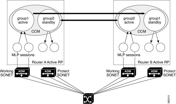
GUID-8E082ED7-5A52-40ED-84C0-A0DC1FD30B2EB shows MLPPP sessions in an MR-APS configuration before an active APS group fails. On Router A active RP, group1 is CCM group 1 and group2 is CCM group 2. All sessions of group1 are active and all sessions of group2 are standby on Router A. Similarly, on Router B, all sessions of group2 are active and all sessions of group1 are in standby state.
When an APS group on Router A fails, the APS informs the corresponding standby APS group on Router B to take over as the active APS group. Here APS will be enhanced to inform CCM about the failure to the corresponding CCM group. The CCM group takes over as the active group and all sessions in that group will become active, while the previous active CCM group reinitializes itself before moving into the standby state. Figure 3 shows how MLPPP sessions switch over after the failure of an active APS group.
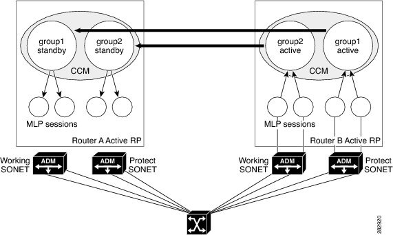
The standby group1 on the remote router takes over as the active group and reinitializes itself before going into the standby state.
RP Failure and Node Failure
ICRM treats an active RP failure as a complete node failure and sends the go-active event to all standby CCM groups directing them to take over as active. Also, all standby APS groups move to active state on receiving the go-active event message, ensuring that both the APS and CCM groups are in the same state, even though APS can detect node failure on its own. Standby CCM groups take over as active and RGF updates its groups with the "peer not available" status.
When the failed node comes up, ICRM establishes fresh connectivity and RGF connects to all groups on the remote router that is becoming active. Since peer groups are detected, RGF ensures bulk syncing of active CCM groups. The standby groups on the peer box receive this bulk sync data and automatically move into a hot-standby state.
GUID-B7F87B69-8539-46D7-ACE0-6C2062F305354 shows CCM/APS groups on two peer nodes: Router A and Router B.
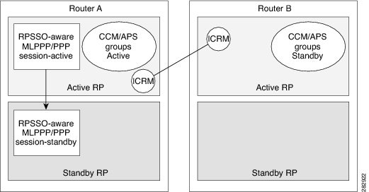
When the active RP of Router A fails, applications using ICRM should switch over to Router B (remote box). Consequently, all APS/CCM groups should switch over to Router B. Now, Router B has all the active APS/CCM groups. All APS/CCM groups on the standby RP of Router A are set to Init state after the standby RP changes to the active RP on Router A. Applications that are RP SSO aware (non-ICRM clients) switch over to the standby RP on Router A. Figure 5 shows APS groups after the active RP on Router A fails.
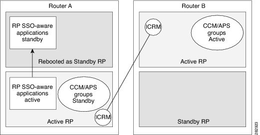
The ICRM establishes fresh connections with the new active RP on Router A and APS synchronizes the group states from Router B to Router A in the standby state. This event triggers all APS groups on Router A to go to the standby state, and the synchronization process is initiated from Router B. On Router A, the failed RP reboots as the new standby RP and RP SSO-aware applications are synchronized to the new standby RP.
How to Configure Stateful MLPPP with MR-APS
- Setting Up an ICRM Session
- Setting Up the BFD Interval
- Configuring the SONET Controller
- Configuring the Serial Interface to Enable MLPPP
- Configuring the Multilink Interface
- Configuring the APS Group for the SONET Controller
- Verifying the Functionality of Stateful MLPPP with MR-APS
Setting Up an ICRM Session
Perform this task on both the working and the protect router to set up ICRM sessions to establish communication between the routers.
DETAILED STEPS
Setting Up the BFD Interval
Perform this task on both the working and the protect router to set up the baseline Bidirectional Forwarding Detection (BFD) parameters between the routers.
DETAILED STEPS
| Command or Action | Purpose | |
|---|---|---|
Step 1 |
enable
Example: Router> enable |
Enables privileged EXEC mode. Enter your password if prompted. |
Step 2 |
configure
terminal
Example: Router# configure terminal |
Enters global configuration mode. |
Step 3 |
interface
gigabitethernet
slot
/
subplot
/
port
Example: Router(config)# interface GigabitEthernet3/1/0 |
Specifies the Gigabit Ethernet interface to be configured, where slot/subslot/port specifies the location of the interface. |
Step 4 |
ip
address
ip-address
subnet-mask
Example: Router(config-if)# ip address 10.1.1.1 255.255.255.0 |
Configures the IP address for the interface. |
Step 5 |
load-interval
seconds
Example: Router(config-if)# load-interval 30 |
Sets the length of time for which data is used for load calculations. |
Step 6 |
negotiation
{forced| auto} Example: Router(config-if)# negotiation auto |
Enables the negotiation of speed, duplex mode, and flow control on a Gigabit Ethernet interface. |
Step 7 |
mpls
ip
Example: Router(config-if)# mpls ip |
Enables MPLS. |
Step 8 |
mpls
label
protocol
{ldp | tdp | both} Example: Router(config-if)# mpls label protocol both |
Configures the label or tag distribution protocol or both on the interface. |
Step 9 |
bfd
interval
milliseconds
min_rx
milliseconds
multiplier
interval-multiplier
Example: Router(config-if)# bfd interval 50 min_rx 150 multiplier 3 |
Configures the transmit interval between BFD packets. |
Step 10 |
end
Example: Router(config-if)# end |
Exits interface configuration mode and returns to privileged EXEC mode. |
Configuring the SONET Controller
Perform this task on the working and the protect router to configure SONET controllers on the routers.
DETAILED STEPS
Configuring the Serial Interface to Enable MLPPP
Perform this task on both the working and the protect router to configure the serial interface to enable MLPPP sessions on the routers.
DETAILED STEPS
Configuring the Multilink Interface
DETAILED STEPS
Configuring the APS Group for the SONET Controller
Perform this task on both the working and protect router to configure the APS group for a SONET controller.
DETAILED STEPS
| Command or Action | Purpose | |
|---|---|---|
Step 1 |
enable
Example: Router> enable |
Enables privileged EXEC mode. Enter your password if prompted. |
Step 2 |
configure
terminal
Example: Router# configure terminal |
Enters global configuration mode. |
Step 3 |
controller
sonet
slot
/
bay
/
port
Example: Router(config)# controller sonet 3/2/0 |
Selects and configures a SONET controller and enters controller configuration mode. |
Step 4 |
shutdown
Example: Router(config-controller)# shutdown |
Shuts down the SONET controller. |
Step 5 |
aps
group
group-id
Example: Router(config-controller)# aps group 1 |
Configures an APS group for the SONET controller. |
Step 6 |
aps
[working| protect] aps-group-number[ip-address-working-router] Example: Router(config-controller)# aps working 1 10.2.2.1 |
Configures the APS group as the working or protect interface, depending on whether the router is the working router or the protect router. The ip-address-working-router attribute is only required while configuring the protect router. |
Step 7 |
aps
interchassis
group
group-number
Example: Router(config-controller)# aps interchassis group 1 |
Associates an APS group with an ICRM group number. |
Step 8 |
no
shutdown
Example: Router(config-controller)# no shutdown |
Enables the interface. |
Step 9 |
end
Example: Router(config-controller)# end |
Exits controller configuration mode and returns to privileged EXEC mode. |
Verifying the Functionality of Stateful MLPPP with MR-APS
Perform the following steps to verify the functionality of the Stateful MLPPP with MR-APS feature configured on the working and protect router.
DETAILED STEPS
| Step 1 |
show
aps
Use this command to display detailed information about the APS configuration on the working or protect router. The following is sample output of the command on the protect router: Example:
Router# show aps
SONET 3/2/0 APS Group 1: protect channel 0 (Inactive) (HA)
Working channel 1 at 10.1.1.2 (Enabled) (HA)
bidirectional, non-revertive
PGP timers (extended for HA): hello time=1; hold time=10
hello fail revert time=120
SONET framing; SONET APS signalling by default
Received K1K2: 0x00 0x05
No Request (Null)
Transmitted K1K2: 0x00 0x05
No Request (Null)
Remote APS configuration: (null)
Protect-Router#
The following is sample output of the command on the working router: Example:
Router# show aps
SONET 1/2/0 APS Group 1: working channel 1 (Active) (HA)
Protect at 10.1.1.2
PGP timers (from protect): hello time=1; hold time=10
SONET framing
Remote APS configuration: (null)
|
| Step 2 |
show
rgf
groups
Use this command to get information about the state of the router and the peer. The following is sample output of the command on the protect router: Example:
Router# show rgf groups
Total RGF groups: 1
----------------------------------------------------------
STANDBY RGF GROUP
RGF Group ID : 1
RGF Peer Group ID: 0
ICRM Group ID : 1
APS Group ID : 1
RGF State information:
My State Present : Standby-hot
Previous : Standby-bulk
Peer State Present: Active-fast
Previous: Standby-cold
Misc:
Communication state Up
aps_bulk: 0
aps_stby: 0
peer_stby: 0
-> Driven Peer to [peer Standby Bulk] Progression
-> We sent Bulk Sync start Progression to Active
RGF GET BUF: 366 RGF RET BUF 366
The following is sample output of the command on the working router: Example:
Router# show rgf groups
Total RGF groups: 1
----------------------------------------------------------
ACTIVE RGF GROUP
RGF Group ID : 1
RGF Peer Group ID: 0
ICRM Group ID : 1
APS Group ID : 1
RGF State information:
My State Present : Active-fast
Previous : Standby-cold
Peer State Present: Standby-hot
Previous: Standby-bulk
Misc:
Communication state Up
aps_bulk: 0
aps_stby: 0
peer_stby: 0
-> Driven Peer to [Peer Standby Hot] Progression
-> Standby sent Bulk Sync start Progression
RGF GET BUF: 366 RGF RET BUF 366 If the value of "My State Present" is "Standby-hot," the router is in standby state. If the value of "My State Present" is "Active-fast," the router is in active state. |
Configuration Examples for Stateful MLPPP with MR-APS
This section provides the following configuration examples:
Example Configuring Stateful MLPPP with MR-APS on a Working Router
Example Configuring Stateful MLPPP with MR-APS on a Protect Router
- Example Configuring Stateful MLPPP with MR-APS on a Working Router
- Example Configuring Stateful MLPPP with MR-APS on a Protect Router
Example Configuring Stateful MLPPP with MR-APS on a Working Router
This example shows how to configure Stateful MLPPP with MR-APS on a Working Router.
Router> enable
Router# configure terminal
Enter configuration commands, one per line.  End with CNTL/Z.
Router(config)# redundancy
Router(config-red)# interchassis group 1
Router(config-r-ic)# monitor peer bfd
Router(config-r-ic)# member ip 10.1.1.2
Router(config-r-ic)# end
Router#
configure terminal
Enter configuration commands, one per line.  End with CNTL/Z.
Router(config)# interface GigabitEthernet3/1/0 <<<<<<< ICRM link >>>>>>>>
Router(config-if)# ip address 10.1.1.1 255.255.255.0
Router(config-if)# load-interval 30
Router(config-if)# negotiation auto
Router(config-if)# mpls ip
Router(config-if)# mpls label protocol both
Router(config-if)# bfd interval 50 min_rx 150 multiplier 3
Router(config-if)# end
Router# configure terminal
Enter configuration commands, one per line.  End with CNTL/Z.
Router(config-if)# interface GigabitEthernet3/1/1 <<<<< PGP Link>>>>>>>
Router(config-if)# ip address 10.1.1.3 255.255.255.0
Router(config-if)# negotiation auto
Router(config-if)# cdp enable
Router(config-if)# end
Router# configure terminal
Enter configuration commands, one per line.  End with CNTL/Z.
Router(config)#controller SONET 4/2/0
Router(config-controller)# no ais-shut
Router(config-controller)# framing sonet
Router(config-controller)# clock source line
Router(config-controller)# sts-1 1
Router(config-ctrlr-sts1)# mode vt-15
Router(config-ctrlr-sts1)# vtg 1 t1 1 channel-group 0 timeslots 1-24
Router(config-ctrlr-sts1)# end
Router# configure terminal
Enter configuration commands, one per line.  End with CNTL/Z.
Router(config)# interface Multilink1
Router(config-if)# ip address 10.1.1.4 255.255.255.0
Router(config-if)# carrier-delay msec 1
Router(config-if)# ppp multilink
Router(config-if)# ppp multilink group 1
Router(config-if)# ppp multilink endpoint string mlp_aps_1
Router(config-if)# ppp timeout retry 0 250
Router(config-if)# end
Router# configure terminal
Enter configuration commands, one per line.  End with CNTL/Z.
Router(config)# interface Serial4/2/0.1/1/1:0
Router(config-if)# no ip address
Router(config-if)# encapsulation ppp
Router(config-if)# ppp multilink
Router(config-if)# ppp multilink group 1
Router(config-if)# end
Router# configure terminal
Enter configuration commands, one per line.  End with CNTL/Z.
Router(config)# controller sonet 3/2/0
Router(config-controller)# shutdown
Router(config-controller)# aps group 1
Router(config-controller)# aps working 1
Router(config-controller)# aps interchassis group 1
Router(config-controller)# no shutdown
Router(config-controller)# end
Example Configuring Stateful MLPPP with MR-APS on a Protect Router
This example shows how to configure Stateful MLPPP with MR-APS on a Protect router.
Protect-Router> enable
Protect-Router# configure terminal
Enter configuration commands, one per line.  End with CNTL/Z.
Router(config)# redundancy
Router(config-red)# interchassis group 1
Router(config-r-ic)# monitor peer bfd
Router(config-r-ic)# member ip 10.1.1.7
Router(config-r-ic)# end
Router# configure terminal
Enter configuration commands, one per line.  End with CNTL/Z.
Router(config)# interface GigabitEthernet2/1/0
Router(config-if)# ip address 10.1.1.8 255.255.255.0
Router(config-if)# load-interval 30
Router(config-if)# negotiation auto
Router(config-if)# mpls ip
Router(config-if)# mpls label protocol both
Router(config-if)# bfd interval 50 min_rx 150 multiplier 3
Router(config-if)# end
Router# configure terminal
Enter configuration commands, one per line.  End with CNTL/Z.
Router(config-if)# interface GigabitEthernet2/1/1
Router(config-if)# ip address 10.1.1.9 255.255.255.0
Router(config-if)# negotiation auto
Router(config-if)# end
Router# configure terminal
Enter configuration commands, one per line.  End with CNTL/Z.
Router(config)#controller SONET 3/2/0
Router(config-controller)# no ais-shut
Router(config-controller)# framing sonet
Router(config-controller)# clock source line
Router(config-controller)# sts-1 1
Router(config-ctrlr-sts1)# mode vt-15
Router(config-ctrlr-sts1)# vtg 1 t1 1 channel-group 0 timeslots 1-24
Router(config-ctrlr-sts1)# end
Router# configure terminal
Enter configuration commands, one per line.  End with CNTL/Z.
Router(config)# interface Multilink1
Router(config-if)# ip address 10.1.1.10 255.255.255.0
Router(config-if)# carrier-delay msec 1
Router(config-if)# ppp multilink
Router(config-if)# ppp multilink group 1
Router(config-if)# ppp multilink endpoint string mlp_aps_1
Router(config-if)# ppp timeout retry 0 250
Router(config-if)# end
Router# configure terminal
Enter configuration commands, one per line.  End with CNTL/Z.
Router(config)# interface Serial3/2/0.1/1/1:0
Router(config-if)# no ip address
Router(config-if)# encapsulation ppp
Router(config-if)# ppp multilink
Router(config-if)# ppp multilink group 1
Router(config-if)# end
Router# configure terminal
Enter configuration commands, one per line.  End with CNTL/Z.
Router(config)# controller sonet 3/2/0
Router(config-controller)# shut
Router(config-controller)# aps group 1
Router(config-controller)# aps protect 1 10.1.1.3
Router(config-controller)# aps interchassis group 1
Router(config-controller)# no shutdown
Router(config-controller)# end
Additional References
Related Documents
MIBs
Technical Assistance
|
Description |
Link |
|---|---|
|
The Cisco Support and Documentation website provides online resources to download documentation, software, and tools. Use these resources to install and configure the software and to troubleshoot and resolve technical issues with Cisco products and technologies. Access to most tools on the Cisco Support and Documentation website requires a Cisco.com user ID and password. |
Feature Information for Stateful MLPPP with MR-APS
GUID-E656E13E-5E5B-4B53-A1DF-FD99D877DFB8B lists the features in this module and provides links to specific configuration information.
Use Cisco Feature Navigator to find information about platform support and software image support. Cisco Feature Navigator enables you to determine which software images support a specific software release, feature set, or platform. To access Cisco Feature Navigator, go to http://www.cisco.com/go/cfn . An account on Cisco.com is not required.
GUID-E656E13E-5E5B-4B53-A1DF-FD99D877DFB8B lists only the software release that introduced support for a given feature in a given software release train. Unless noted otherwise, subsequent releases of that software release train also support that feature.
| Table 1 | Feature Information for the Stateful MLPPP with MR-APS feature |
|
Feature Name |
Releases |
Feature Information |
|---|---|---|
|
Stateful MLPPP with MR-APS |
15.1(3)S |
The Stateful MLPPP with MR-APS feature supports IC-SSO for MLPPP sessions, thereby allowing MR-APS from one router to another, while maintaining the MLPPP sessions and avoiding session renegotiation. This feature is available only on Cisco 7600 series routers. In Cisco IOS Release 15.1(3)S, this feature was introduced on the Cisco 7600 series routers. The following sections provide information about this feature: The following commands were introduced or modified: aps interchassis group, debug rgf detail, debug rgf error, debug rgf event, show ccm group all, show ccm group id, show ccm session id, show rgf groups, show rgf history, show rgf statistics. |