
 Feedback
Contents
- Layer 2 Local Switching
- Finding Feature Information
- Prerequisites for Layer 2 Local Switching
- Restrictions for Layer 2 Local Switching
- Cisco 7200 and 7500 Series Router Restrictions
- Cisco 7600 and 6500 Series Router Restrictions
- Cisco 10000 Series Router Restrictions
- Gigabit Switch Router Restrictions
- Unsupported Hardware
- Information About Layer 2 Local Switching
- Layer 2 Local Switching Overview
- NSF SSO - Local Switching Overview
- Layer 2 Local Switching Applications
- Access Circuit Redundancy Local Switching
- ACR for ATM-to-ATM Local Switching
- ACR for CEM-to-CEM Local Switching
- How to Configure Layer 2 Local Switching
- Configuring ATM-to-ATM PVC Local Switching and Same-Port Switching
- Configuring ATM-to-ATM PVP Local Switching
- Configuring ATM PVP Same-Port Switching
- Configuring ATM-to-Ethernet Port Mode Local Switching
- Configuring ATM-to-Ethernet VLAN Mode Local Switching
- Configuring Ethernet VLAN Same-Port Switching
- Configuring Ethernet Port Mode to Ethernet VLAN Local Switching
- Configuring ATM-to-Frame Relay Local Switching
- Configuring Frame Relay-to-Frame Relay Local Switching
- Configuring Frame Relay Same-Port Switching
- Configuring HDLC Local Switching
- Configuring ACR for ATM-to-ATM Local Switching
- Configuring CEM-to-CEM ACR Local Switching
- Verifying Layer 2 Local Switching
- Verifying Layer 2 Local Switching Configuration
- Verifying the NSF SSO Local Switching Configuration
- Troubleshooting Tips
- Configuration Examples for Layer 2 Local Switching
- Example ATM-to-ATM Local Switching
- Example ATM PVC Same-Port Switching
- Example ATM PVP Same-Port Switching
- Example ATM-to-Ethernet Local Switching
- Example ATM to Ethernet VLAN
- Example ATM to Ethernet Port Mode
- Example Ethernet VLAN Same-Port Switching
- Example ATM-to-Frame Relay Local Switching
- Example Frame Relay-to-Frame Relay Local Switching
- Example Frame Relay DLCI Same-Port Switching
- Example HDLC Local Switching
- Example NSF SSO Ethernet Port Mode to Ethernet VLAN Local Switching
- Additional References
- Feature Information for Layer 2 Local Switching
Layer 2 Local Switching
The Layer 2 Local Switching feature allows you to switch Layer 2 data in two ways:
- Between two interfaces on the same router
- Between two circuits on the same interface port, which is called same-port switching
The interface-to-interface switching combinations supported by this feature are:
- ATM to ATM
- ATM to Ethernet
- ATM to Frame Relay
- Ethernet to Ethernet VLAN
- Frame Relay to Frame Relay (and Multilink Frame Relay in Cisco IOS Release 12.0(28)S and later)
- High-Level Data Link Control (HDLC)
The following same-port switching features are supported:
- Finding Feature Information
- Prerequisites for Layer 2 Local Switching
- Restrictions for Layer 2 Local Switching
- Information About Layer 2 Local Switching
- How to Configure Layer 2 Local Switching
- Configuration Examples for Layer 2 Local Switching
- Additional References
- Feature Information for Layer 2 Local Switching
Finding Feature Information
Your software release may not support all the features documented in this module. For the latest feature information and caveats, see the release notes for your platform and software release. To find information about the features documented in this module, and to see a list of the releases in which each feature is supported, see the Feature Information Table at the end of this document.
Use Cisco Feature Navigator to find information about platform support and Cisco software image support. To access Cisco Feature Navigator, go to www.cisco.com/go/cfn. An account on Cisco.com is not required.
Prerequisites for Layer 2 Local Switching
- You must enable Cisco Express Forwarding for the Cisco 7200 series router. You must use Cisco Express Forwarding or Distributed Cisco Express Forwarding for the Cisco 7500 series router. (Distributed Cisco Express Forwarding is enabled already by default on the Gigabit Switch Router [GSR]).
- For Frame Relay local switching, you must globally issue the frame-relay switchingcommand.
Restrictions for Layer 2 Local Switching
- Cisco 7200 and 7500 Series Router Restrictions
- Cisco 7600 and 6500 Series Router Restrictions
- Cisco 10000 Series Router Restrictions
- Gigabit Switch Router Restrictions
- Unsupported Hardware
Cisco 7200 and 7500 Series Router Restrictions
- In ATM single cell relay AAL0, the ATM virtual path identifier/virtual channel identifier (VPI/VCI) values must match between the ingress and egress ATM interfaces on the Cisco 7200 series and 7500 series routers. If Layer 2 local switching is desired between two ATM VPIs and VCIs whose values do not match and are on two different interfaces, choose ATM AAL5. However, if the ATM AAL5 is using Operation, Administration, and Maintenance (OAM) transparent mode, the VPI and VCI values must match.
- NSF/SSO: Layer 2 local switching is supported on Cisco 7500 series routers.
Layer 2 local switching is supported on the following interface processors in the Cisco 7200 series routers:
- C7200-I/O-2FE
- C7200-I/O-GE+E (Only the Gigabit Ethernet port of this port adapter is supported.)
- C7200-I/O-FE
Layer 2 local switching is supported on the following interface processors in the Cisco 7500 series routers:
- GEIP (Gigabit Ethernet interface processor)
- GEIP+ (enhanced Gigabit Ethernet interface processor)
Layer 2 local switching is supported on the following port adapters in the Cisco 7200 and 7500 series routers:
- PA-FE-TX (single-port Fast Ethernet 100BASE-TX)
- PA-FE-FX (single-port Fast Ethernet 100BASE-FX)
- PA-2FE-TX (dual-port Fast Ethernet 100BASE-TX)
- PA-2FE-FX (dual-port Fast Ethernet 100BASE-FX)
- PA-4E (4-port Ethernet adapter)
- PA-8E (8-port Ethernet adapter)
- PA-4T (4-port synchronous serial port adapter)
- PA-4T+ (enhanced 4-port synchronous serial port adapter)
- PA-8T (8-port synchronous serial port adapter)
- PA-12E/2FE (12-port Ethernet/2-port Fast Ethernet (FE) adapter) [Cisco 7200 only]
- PA-GE (Gigabit Ethernet port adapter) [Cisco 7200 only]
- PA-H (single-port High-Speed Serial Interface (HSSI) adapter)
- PA-2H (dual-port HSSI adapter)
- PA-MC-8E1 (8-port multichannel E1 G.703/G.704 120-ohm interfaces)
- PA-MC-2EI (2-port multichannel E1 G.703/G.704 120-ohm interfaces)
- PA-MC-8T1 (8-port multichannel T1 with integrated data service units (DSUs) and channel service units CSUs))
- PA-MC-4T1 (4-port multichannel T1 with integrated CSUs and DSUs)
- PA-MC-2T1 (2-port multichannel T1 with integrated CSUs and DSUs)
- PA-MC-8TE1+ (8-port multichannel T1/E1)
- PA-MC-T3 (1-port multichannel T3 interface)
- PA-MC-E3 (1-port multichannel E3 interface)
- PA-MC-2T3+ (2-port enhanced multichannel T3 port adapter)
- PA-MC-STM1 (1-port multichannel STM-1 port adapter) [Cisco 7500 only]
- PA-T3 (single-port T3 port adapter)
- PA-E3 (single-port E3 port adapter)
- PA-2E3 (2-port E3 port adapter)
- PA-2T3 (2-port T3 port adapter)
- PA-POS-OC-3SML (single-port Packet over SONET (POS), single-mode, long reach)
- PA-POS-OC-3SMI (single-port PoS, single-mode, intermediate reach)
- PA-POS-OC-3MM (single-port PoS, multimode)
- PA-A3-OC-3 (1-port ATM OC-3/STM1 port adapter, enhanced)
- PA-A3-OC-12 (1-port ATM OC-12/STM-4 port adapter, enhanced) [Cisco 7500 only]
- PA-A3-T3 (DS3 high-speed interface)
- PA-A3-E3 (E3 medium-speed interface)
- PA-A3-8T1IMA (ATM inverse multiplexer over ATM port adapter with 8 T1 ports)
- PA-A3-8E1IMA (ATM inverse multiplexer over ATM port adapter with 8 E1 ports)
- PA-A6 (Cisco ATM Port Adapter)
Cisco 7600 and 6500 Series Router Restrictions
-
Layer 2 local switching supports the following port adapters and interface processors on the Cisco 7600-SUP720/MSFC3 router:
- All port adapters on the Enhanced FlexWAN module
- All shared prot adaptors (SPAs) on the SIP-200 line cards
- On the Cisco 6500 series and 7600 series routers, only like-to-like local switching is supported (ATM to ATM and Frame Relay to Frame Relay).
- Same-port switching is not supported on the Cisco 6500 series and 7600 series routers.
Cisco 10000 Series Router Restrictions
For information about Layer 2 local switching on the Cisco 10000 series routers, see Configuring Layer 2 Local Switching .
Gigabit Switch Router Restrictions
- VPI/VCI rewrite is supported.
- All GSR line cards support Frame Relay-to-Frame Relay local switching.
- 8-port OC-3 ATM Engine 2 line cards support only like-to-like Layer 2 local switching.
- IP Service Engine (ISE) (Engine 3) line cards support like-to-like and any-to-any local switching. Non-ISE line cards support only like-to-like local switching.
Starting in Cisco IOS Release 12.0(31)S2, ISE customer edge-facing interfaces support the following types of like-to-like and any-to-any local switching:
 Note | Native Layer 2 Tunnel Protocol Version 3 (L2TPv3) tunnel sessions on customer edge-facing line cards can coexist with tunnel sessions that use a tunnel-server card. |
- Starting in Cisco IOS Release 12.0(32)SY, customer edge-facing interfaces on Engine 5 SPAs and SPA Interface Processors (SIPs) support the following types of like-to-like local switching:
- For ATM-to-ATM local switching, the following ATM types are supported for the Layer 2 Local Switching feature:
- Starting with Cisco IOS Release 12.0(30)S, you can use local switching and cell packing with ATM VP or VC mode on the GSR on IP Services Engine (ISE/Engine 3) line cards. For information about how to configure cell packing, refer to Any Transport over MPLS.
Unsupported Hardware
The following hardware is not supported:
- Cisco 7200--non-VXR chassis
- Cisco 7500--Route Switch Processor (RSP)1 and 2
- Cisco 7500--Versatile Interface Processor (VIP) 2-40 and below
- GSR--4-port OC-3 ATM Engine-0 line card
- GSR--4-port OC-12 ATM Engine-2 line card
- GSR--1-port OC-12 ATM Engine-0 line card
- GSR--Ethernet Engine-1, Engine-2, and Engine-4 line cards
Information About Layer 2 Local Switching
- Layer 2 Local Switching Overview
- NSF SSO - Local Switching Overview
- Layer 2 Local Switching Applications
- Access Circuit Redundancy Local Switching
Layer 2 Local Switching Overview
Local switching allows you to switch Layer 2 data between two interfaces of the same type (for example, ATM to ATM, or Frame Relay to Frame Relay) or between interfaces of different types (for example, Frame Relay to ATM) on the same router. The interfaces can be on the same line card or on two different cards. During these kinds of switching, the Layer 2 address is used, not any Layer 3 address.
Additionally, same-port local switching allows you to switch Layer 2 data between two circuits on the same interface.
NSF SSO - Local Switching Overview
Nonstop forwarding (NSF) and stateful switchover (SSO) improve the availability of the network by providing redundant Route Processors (RPs) and checkpointing of data to ensure minimal packet loss when the primary RP goes down. NSF/SSO support is available for the following locally switched attachment circuits:
- Ethernet to Ethernet VLAN
- Frame Relay to Frame Relay
Layer 2 Local Switching Applications
Incumbent local exchange carriers (ILECs) who use an interexchange carrier (IXC) to carry traffic between two local exchange carriers can use the Layer 2 Local Switching feature. Telecom regulations require the ILECs to pay the IXCs to carry that traffic. At times, the ILECs cannot terminate customer connections that are in different local access and transport areas (LATAs). In other cases, customer connections terminate in the same LATA, which may also be on the same router.
For example, company A has more than 50 LATAs across the country and uses three routers for each LATA. Company A uses companies B and C to carry traffic between local exchange carriers. Local switching of Layer 2 frames on the same router might be required.
Similarly, if a router is using, for example, a channelized interface, it might need to switch incoming and outgoing traffic across two logical interfaces that reside on a single physical port. The same-port local switching feature addresses that implementation.
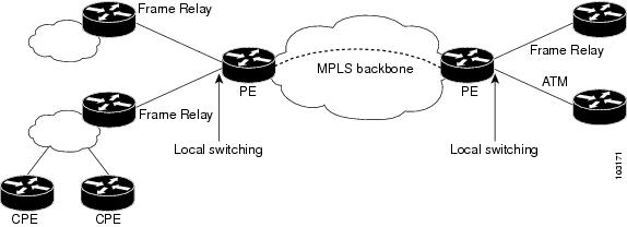
The figure below shows a network that uses local switching for both Frame Relay to Frame Relay and ATM to Frame Relay local switching.
Access Circuit Redundancy Local Switching
The Automatic Protection Switching (APS) mechanism provides a switchover time of less than 50 milliseconds. However, the switchover time is longer in a pseudowire configuration due to the time the pseudowire takes to enter the UP state on switchover. The switchover time of the pseudowire can be eliminated if there is a single pseudowire on the working and protect interfaces instead of separate pseudowire configurations. A single pseudowire also eliminates the need to have Label Distribution Protocols (LDP) negotiations on a switchover. The virtual interface or controller model provides a method to configure a single pseudowire between the provider edge (PE) routers.
Access Circuit Redundancy (ACR) ensures low data traffic downtime by reducing the switchover time. ACR works on the APS 1+1, nonrevertive model where each redundant line pair consists of a working line and a protect line. If a signal fail condition or a signal degrade condition is detected, the hardware switches from the working line to the protect line.
The working and protect interfaces can be on the following:
- Same SPA
- Different SPA but on the same line card
- SPAs on different line cards
When the working or protection interface is configured with ACR, a virtual interface is created and a connection is established between the virtual interfaces to facilitate the switching of data between the interfaces.
ACR for ATM-to-ATM Local Switching
ACR for ATM-to-ATM local switching supports the ATM AAL5 and ATM AAL0 encapsulation types and switches Layer 2 data between L2 transport virtual circuits (VCs).
Note | The L2 transport VCs must be configured with the same encapsulation type. |
The figure below shows the ACR for ATM-to-ATM local switching model.
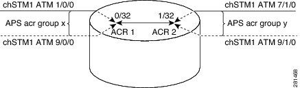
In the figure:
- ATM 1/0/0 and ATM 9/0/0 are configured as working and protection interfaces of ACR 1 group.
- ATM 7/1/0 and ATM 9/1/0 are configured as working and protection interfaces of ACR 2 group.
- A connection is established between the ACRs.
- The Add/Drop Multiplexer (ADM) sends data to both the interfaces, which are part of the ACR group ACR 1.
- The cells or packets received on the APS active interface VC (0/32) of ACR group 1 are switched to the ACR 2 interface VC (1/32) and the cells or packets from the APS inactive interface are dropped.
- The packets received on the ACR 2 VC (1/32) interface are replicated on both the physical interfaces, which are part of the ACR group ACR 2.
ACR for CEM-to-CEM Local Switching
Circuit Emulation (CEM) transports Time Division Multiplexing (TDM) data over TDM pseudowires, allowing mobile operators to carry TDM traffic over an IP or Multiprotocol Label Switching (MPLS) network. ACR for CEM-to-CEM involves creating a virtual controller and associating the virtual controller with the physical controllers. The virtual controller is created when APS and ACR are configured on the physical controller. All commands executed on the virtual controller apply to the working and protect controller. The virtual controller simplifies the single point of configuration and provides the flexibility of not running a backup pseudowire for the protect controller in the event of a failure. This way there is no switchover between the pseudowires, which in turn reduces the recovery time when the physical link fails.
When the CEM group is configured on the virtual controller, a virtual CEM-ACR interface is created and associated with the CEM circuit. ACR creates CEM interfaces and CEM circuits on the physical interfaces that correspond to the physical controllers belonging to the same ACR group.
The figure below shows the ACR for CEM-to-CEM local switching model:
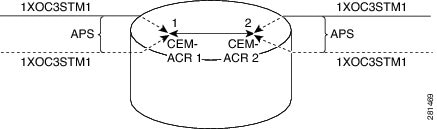
In the figure:
- Packets are received from the ADM. The packets from the APS inactive interface are dropped and the packets received on the APS active interface are switched.
- The packets received on the CEM circuit ID 1 of the APS active interface, which is part of ACR group 1, are switched to the CEM circuit ID 2 of the APS active interface, which is part of ACR group 2.
- The packets are duplicated and sent on both the APS active and inactive physical CEM interfaces that are part of ACR group 2.
How to Configure Layer 2 Local Switching
For information about Layer 2 local switching on the Cisco 10000 series routers, see Configuring Layer 2 Local Switching .
- Configuring ATM-to-ATM PVC Local Switching and Same-Port Switching
- Configuring ATM-to-ATM PVP Local Switching
- Configuring ATM PVP Same-Port Switching
- Configuring ATM-to-Ethernet Port Mode Local Switching
- Configuring ATM-to-Ethernet VLAN Mode Local Switching
- Configuring Ethernet VLAN Same-Port Switching
- Configuring Ethernet Port Mode to Ethernet VLAN Local Switching
- Configuring ATM-to-Frame Relay Local Switching
- Configuring Frame Relay-to-Frame Relay Local Switching
- Configuring Frame Relay Same-Port Switching
- Configuring HDLC Local Switching
- Configuring ACR for ATM-to-ATM Local Switching
- Configuring CEM-to-CEM ACR Local Switching
- Verifying Layer 2 Local Switching
Configuring ATM-to-ATM PVC Local Switching and Same-Port Switching
You can configure local switching for both ATM AAL5 and ATM AAL0 encapsulation types.
Creating the ATM PVC is not required. If you do not create a PVC, one is created for you. For ATM-to-ATM local switching, the autoprovisioned PVC is given the default encapsulation type AAL0 cell relay.
Note | Starting with Cisco IOS Release 12.0(30)S, you can configure same-port switching following the steps in this section. |
DETAILED STEPS
Configuring ATM-to-ATM PVP Local Switching
Perform this task to configure ATM-to-ATM PVP local switching.
Starting with Cisco IOS Release 12.0(30)S, you can configure same-port switching, as detailed in the Configuring ATM PVP Same-Port Switching.
DETAILED STEPS
Configuring ATM PVP Same-Port Switching
DETAILED STEPS
Configuring ATM-to-Ethernet Port Mode Local Switching
For ATM to Ethernet port mode local switching, creating the ATM PVC is not required. If you do not create a PVC, one is created for you. For ATM-to-Ethernet local switching, the autoprovisioned PVC is given the default encapsulation type AAL5SNAP.
ATM-to-Ethernet local switching supports both the IP and Ethernet interworking types. When the Ethernet interworking type is used, the interworking device (router) expects a bridged packet. Therefore, configure the ATM CPE for either IRB or RBE.
Note | Enabling ICMP Router Discovery Protocol on the Ethernet side is recommended. |
ATM-to-Ethernet local switching supports the following encapsulation types:
- ATM-to-Ethernet with IP interworking: AAL5SNAP, AAL5MUX
- ATM-to-Ethernet with Ethernet interworking: AAL5SNAP
Perform this task to configure local switching between ATM and Ethernet port mode.
DETAILED STEPS
Configuring ATM-to-Ethernet VLAN Mode Local Switching
For ATM-to-Ethernet VLAN mode local switching, creating the ATM PVC is not required. If you do not create a PVC, one is created for you. For ATM-to-Ethernet local switching, the autoprovisioned PVC is given the default encapsulation type AAL5SNAP.
ATM-to-Ethernet local switching supports both the IP and Ethernet interworking types. When the Ethernet interworking type is used, the interworking device (router) expects a bridged packet. Therefore, configure the ATM CPE for either IRB or RBE.
Note | Enabling ICMP Router Discovery Protocol on the Ethernet side is recommended. |
ATM-to-Ethernet local switching supports the following encapsulation types:
- ATM-to-Ethernet with IP interworking: AAL5SNAP, AAL5MUX
- ATM-to-Ethernet with Ethernet interworking: AAL5SNAP
The VLAN header is removed from frames that are received on an Ethernet subinterface.
Perform this task to configure local switching for ATM to Ethernet in VLAN mode.
DETAILED STEPS
Configuring Ethernet VLAN Same-Port Switching
DETAILED STEPS
Configuring Ethernet Port Mode to Ethernet VLAN Local Switching
DETAILED STEPS
Configuring ATM-to-Frame Relay Local Switching
You use the interworking ipkeywords for configuring ATM-to-Frame Relay local switching.
FRF.8 Frame Relay-to-ATM service interworking functionality is not supported. Frame Relay discard-eligible (DE) bits do not get mapped to ATM cell loss priority (CLP) bits, and forward explicit congestion notification (FECN) bits do not get mapped to ATM explicit forward congestion indication (EFCI) bits.
Creating the PVC is not required. If you do not create a PVC, one is created for you. For ATM-to-Ethernet local switching, the automatically provisioned PVC is given the default encapsulation type AAL5SNAP.
ATM-to-Frame Relay local switching supports the following encapsulation types:
- AAL5SNAP
- AAL5NLPID (GSR uses AAL5MUX instead, for IP interworking)
DETAILED STEPS
Configuring Frame Relay-to-Frame Relay Local Switching
For information on Frame Relay-to-Frame Relay Local Switching, see the Distributed Frame Relay Switching feature module.
With Cisco IOS Release 12.0(30)S, you can switch between virtual circuits on the same port, as detailed in the Configuring Frame Relay Same-Port Switching.
DETAILED STEPS
Configuring Frame Relay Same-Port Switching
DETAILED STEPS
Configuring HDLC Local Switching
Perform this task to configure local switching for HDLC. The PE routers are configured with HDLC encapsulation. The CE routers are configured with any HDLC-based encapsulation, including HDLC, PPP, and Frame Relay.
- Ensure that the interfaces you configure for HDLC encapsulation can handle ping packets that are smaller, the same size as, or larger than the CE interface MTU.
- Enable Cisco Express Forwarding.
DETAILED STEPS
Configuring ACR for ATM-to-ATM Local Switching
Note | The connect command provides an infrastructure to create the required L2 transport VCs with the default AAl0 encapsulation type and does not require that the VCs must exist. |
Perform this task to configure ACR for ATM-to-ATM local switching.
DETAILED STEPS
Configuring CEM-to-CEM ACR Local Switching
DETAILED STEPS
Verifying Layer 2 Local Switching
- Verifying Layer 2 Local Switching Configuration
- Verifying the NSF SSO Local Switching Configuration
- Troubleshooting Tips
Verifying Layer 2 Local Switching Configuration
To verify configuration of the Layer 2 Local Switching feature, use the following commands on the provider edge (PE) router:
DETAILED STEPS
| Step 1 |
show
connection
[all | element | id id | name name | port port] The show connectioncommand displays the local connection between an ATM interface and a Fast Ethernet interface: Example:
Router# show connection name atm-eth-con
ID  Name            Segment 1              Segment 2         State
==================================================================
1   atm-eth-con     ATM0/0/0 AAL5 0/100    FastEthernet6/0/0  UP
This example displays the local connection between an ATM interface and a serial interface: Example:
Router# show connection name atm-fr-con
ID  Name            Segment 1              Segment 2         State
==================================================================
1   atm-fr-con     ATM0/0/0 AAL5 0/100    Serial1/0/0  16     UP
This example displays a same-port connection on a serial interface. Example:
Router# show connection name same-port
ID  Name            Segment 1              Segment 2         State
==================================================================
1   same-port      Serial1/1/1  101       Serial1/1/1  102    UP
|
| Step 2 |
show
atm
pvc
The show atm pvccommand shows that interface ATM3/0 is UP: Example:
Router# show atm pvc
            VCD/                                      Peak   Avg/Min   Burst
Interface   Name   VPI   VCI   Type   Encaps      SC  Kbps   Kbps      Cells    Sts
3/0         10     1     32    PVC    FRATMSRV    UBR 155000                    UP
|
| Step 3 |
show
frame-relay
pvc
[pvc] The show frame-relay pvc command shows a switched Frame Relay PVC: Example:
Router# show frame-relay pvc 16
PVC Statistics for interface POS5/0 (Frame Relay NNI)
DLCI = 16, DLCI USAGE = SWITCHED, PVC STATUS = UP, INTERFACE = POS5/0
LOCAL PVC STATUS = UP, NNI PVC STATUS = ACTIVE
input pkts 0 output pkts 0 in bytes 0
out bytes 0 dropped pkts 100 in FECN pkts 0
in BECN pkts 0 out FECN pkts 0 out BECN pkts 0
in DE pkts 0 out DE pkts 0
out bcast pkts 0 out bcast bytes 0
switched pkts 0
Detailed packet drop counters:
no out intf 0 out intf down 100 no out PVC 0
in PVC down 0 out PVC down 0 pkt too big 0
pvc create time 00:25:32, last time pvc status changed 00:06:31
|
Verifying the NSF SSO Local Switching Configuration
Layer 2 local switching provides NSF/SSO support for Local Switching of the following attachment circuits on the same router:
For information about configuring NSF/SSO on the RPs, see the Stateful Switchover feature module. To verify that the NSF/SSO: Layer 2 Local Switching is working correctly, follow the steps in this section.
DETAILED STEPS
Configuration Examples for Layer 2 Local Switching
- Example ATM-to-ATM Local Switching
- Example ATM PVC Same-Port Switching
- Example ATM PVP Same-Port Switching
- Example ATM-to-Ethernet Local Switching
- Example Ethernet VLAN Same-Port Switching
- Example ATM-to-Frame Relay Local Switching
- Example Frame Relay-to-Frame Relay Local Switching
- Example Frame Relay DLCI Same-Port Switching
- Example HDLC Local Switching
- Example NSF SSO Ethernet Port Mode to Ethernet VLAN Local Switching
Example ATM-to-Ethernet Local Switching
Example ATM to Ethernet VLAN
The following example shows an Ethernet interface configured for Ethernet VLAN, and an ATM PVC interface configured for AAL5 encapsulation. The connectcommand allows local switching between these two interfaces and specifies the interworking type as Ethernet mode.
interface fastethernet6/0/0.1
 encapsulation dot1q 10
interface atm2/0/0
 pvc 0/400 l2transport
 encapsulation aal5
connect atm-ethvlan-con atm2/0/0 0/400 fastethernet6/0/0.1 interworking ethernet
Example ATM to Ethernet Port Mode
The following example shows an Ethernet interface configured for Ethernet and an ATM interface configured for AAL5SNAP encapsulation. The connectcommand allows local switching between these two interfaces and specifies the interworking type as IP mode.
interface atm0/0/0
 pvc 0/100 l2transport
 encapsulation aal5snap
interface fastethernet6/0/0
connect atm-eth-con atm0/0/0 0/100 fastethernet6/0/0 interworking ip
Example ATM-to-Frame Relay Local Switching
The following example shows a serial interface configured for Frame Relay and an ATM interface configured for AAL5SNAP encapsulation. The connectcommand allows local switching between these two interfaces.
interface serial1/0
 encapsulation frame-relay
interface atm1/0
 pvc 7/100 l2transport
 encapsulation aal5snap
connect atm-fr-conn atm1/0 7/100 serial1/0 100 interworking ip
Example Frame Relay-to-Frame Relay Local Switching
The following example shows serial interfaces configured for Frame Relay. The connectcommand allows local switching between these two interfaces.
frame-relay switching
ip cef distributed
interface serial3/0/0
 encapsulation frame-relay
 frame-relay interface-dlci 100 switched
 frame-relay intf-type dce
interface serial3/1/0
 encapsulation frame-relay ietf
 frame-relay interface-dlci 200 switched
 frame-relay intf-type dce
connect fr-con serial3/0/0 100 serial3/1/0 200
Example NSF SSO Ethernet Port Mode to Ethernet VLAN Local Switching
The following configuration uses the network topology shown in the figure below.
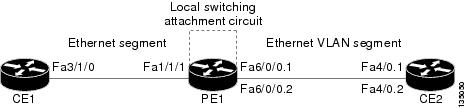
The following example shows the configuration of the CE interfaces to connect to the PE1 router:
|
CE1 |
CE2 |
|---|---|
ip routing ! interface fa3/1/0 description: connection to PE fa1/1/1 no shutdown ip address 10.1.1.1 255.255.255.0 |
ip routing ! interface fa4/0 no shutdown ! interface fa4/0.1 description: connection to PE1 fa6/0/0.1 encapsulation dot1Q 10 ip address 10.1.1.2 255.255.255.0 ! interface fa4/0.2 description - connection to PE1 fa6/0/0.2 encapsulation dot1Q 20 ip address 172.16.1.2 255.255.255.0 |
The following example shows the configuration of the PE1 router with NSF/SSO and the PE interfaces to the CE routers:
|
PE1 |
|---|
redundancy no keepalive-enable mode sso ! hw-module slot 2 image disk0:rsp-pv-mz.shaft.111004 hw-module slot 3 image disk0:rsp-pv-mz.shaft.111004 ! ip routing ip cef distributed ! interface fa1/1/1 description - connection to CE1 fa3/1/0 no shutdown no ip address ! interface fa4/0/0 description - connection to CE3 fa6/0 no shutdown no ip address ! interface fa6/0/0 no shutdown no ip address ! interface fa6/0/0.1 description - connection to CE2 fa4/0.1 encapsulation dot1Q 10 no ip address ! interface fa6/0/0.2 description - connection to CE2 fa4/0.2 encapsulation dot1Q 20 no ip address |
The following example shows the configuration of ICMP Router Discovery Protocol (IRDP) on the CE router for Interworking IP for ARP mediation:
|
CE1 |
CE2 |
|---|---|
interface FastEthernet3/1/0 ip irdp ip irdp maxadvertinterval 0 |
interface FastEthernet4/0.1 ip irdp ip irdp maxadvertinterval 0 |
The following example shows the configuration of OSPF on the CE routers:
|
CE1 |
CE2 |
|---|---|
interface loopback 1 ip address 10.11.11.11 255.255.255.255 ! router ospf 10 network 10.11.11.11 0.0.0.0 area 0 network 192.168.1.1 0.0.0.0 area 0 |
interface loopback 1 ip address 12.12.12.12 255.255.255.255 ! router ospf 10 network 10.12.12.12 0.0.0.0 area 0 network 192.168.1.2 0.0.0.0 area 0 |
The following example shows the configuration of local switching on the PE1 router for interworking Ethernet:
connect eth-vlan1 fa1/1/1 fa6/0/0.1 interworking ethernet
connect eth-vlan2 fa4/0/0 fa6/0/0.2 interworking ethernet
The following example shows the configuration of local switching on the PE1 router for interworking IP:
connect eth-vlan1 fa1/1/1 fa6/0/0.1 interworking ip
connect eth-vlan2 fa4/0/0 fa6/0/0.2 interworking ip
Additional References
Related Documents
|
Related Topic |
Document Title |
|---|---|
|
MPLS |
MPLS Product Literature |
|
Layer 2 local switching configuration tasks |
|
|
Frame Relay-ATM interworking configuration tasks |
Configuring Frame Relay-ATM Interworking |
|
Frame Relay-to-Frame Relay local switching configuration tasks |
Distributed Frame Relay Switching |
|
CEoP and Channelized ATM SPAs on 7600 series router configuration tasks |
Standards
|
Standard |
Title |
|---|---|
|
draft-ietf-l2tpext-l2tp-base-03.txt |
Layer Two Tunneling Protocol (Version 3) 'L2TPv3' |
|
draft-martini-l2circuit-trans-mpls-09.txt |
Transport of Layer 2 Frames Over MPLS |
|
draft-martini-l2circuit-encap-mpls-04.txt |
Encapsulation Methods for Transport of Layer 2 Frames Over IP and MPLS Networks |
|
draft-ietf-ppvpn-l2vpn-00.txt |
An Architecture for L2VPNs |
MIBs
Technical Assistance
|
Description |
Link |
|---|---|
|
The Cisco Support and Documentation website provides online resources to download documentation, software, and tools. Use these resources to install and configure the software and to troubleshoot and resolve technical issues with Cisco products and technologies. Access to most tools on the Cisco Support and Documentation website requires a Cisco.com user ID and password. |
Feature Information for Layer 2 Local Switching
The following table provides release information about the feature or features described in this module. This table lists only the software release that introduced support for a given feature in a given software release train. Unless noted otherwise, subsequent releases of that software release train also support that feature.
Use Cisco Feature Navigator to find information about platform support and Cisco software image support. To access Cisco Feature Navigator, go to www.cisco.com/go/cfn. An account on Cisco.com is not required.
| Table 1 | Feature Information for Layer 2 Local Switching |
Cisco and the Cisco logo are trademarks or registered trademarks of Cisco and/or its affiliates in the U.S. and other countries. To view a list of Cisco trademarks, go to this URL: www.cisco.com/go/trademarks. Third-party trademarks mentioned are the property of their respective owners. The use of the word partner does not imply a partnership relationship between Cisco and any other company. (1110R)
Any Internet Protocol (IP) addresses and phone numbers used in this document are not intended to be actual addresses and phone numbers. Any examples, command display output, network topology diagrams, and other figures included in the document are shown for illustrative purposes only. Any use of actual IP addresses or phone numbers in illustrative content is unintentional and coincidental.