
 Feedback
Contents
- Layer 2 Tunneling Protocol Version 3
- Finding Feature Information
- Prerequisites for Layer 2 Tunneling Protocol Version 3
- Restrictions for Layer 2 Tunneling Protocol Version 3
- General L2TPv3 Restrictions
- Cisco 7200 Series and Cisco 7301 Specific Restrictions
- Cisco 7304 Specific Restrictions
- Cisco 7500 Series-Specific Restrictions
- Supported Shared Port Adapters for the Cisco 7600 Series Router
- Cisco 7600 Series-Specific Restrictions
- Cisco 10720-Specific Restrictions
- Cisco 12000 Series-Specific Restrictions
- Frame Relay-Specific Restrictions
- VLAN-Specific Restrictions
- ATM VP Mode Single Cell Relay over L2TPv3 Restrictions
- ATM AAL5 SDU over L2TPv3 and Single Cell Relay VC Mode over L2TPv3 Restrictions
- ATM Port Mode Cell Relay over L2TPv3 Restrictions
- ATM Cell Packing over L2TPv3 Restrictions
- IPv6 Protocol Demultiplexing for L2TPv3 Restrictions
- L2TPv3 Control Message Hashing Restrictions
- L2TPv3 Digest Secret Graceful Switchover Restrictions
- Quality of Service Restrictions in L2TPv3 Tunneling
- Information About Layer 2 Tunneling Protocol Version 3
- Migration from UTI to L2TPv3
- L2TPv3 Operation
- L2TPv3 Benefits
- L2TPv3 Header Description
- Session ID
- Session Cookie
- Pseudowire Control Encapsulation
- L2TPv3 Features
- Control Channel Parameters
- L2TPv3 Control Channel Authentication Parameters
- Static L2TPv3 Sessions
- Dynamic L2TPv3 Sessions
- Sequencing
- Local Switching
- Distributed Switching
- L2TPv3 Layer 2 Fragmentation
- L2TPv3 Type of Service Marking
- Keepalive
- MTU Handling
- L2TPv3 Control Message Hashing
- L2TPv3 Control Message Rate Limiting
- L2TPv3 Digest Secret Graceful Switchover
- L2TPv3 Pseudowire
- Manual Clearing of L2TPv3 Tunnels
- L2TPv3 Tunnel Management
- Control Message Statistics and Conditional Debugging Command Enhancements
- L2TPv3 Protocol Demultiplexing
- Color Aware Policer on Ethernet over L2TPv3
- Site of Origin for Border Gateway Protocol VPNs
- L2TPv3 Custom Ethertype for Dot1q and QinQ Encapsulations
- L2TPv3 and UTI Feature Comparison
- Supported L2TPv3 Payloads
- Frame Relay
- Port-to-Port Trunking
- DLCI-to-DLCI Switching
- PVC Status Signaling
- Sequencing
- ToS Marking
- CIR Guarantees
- Binding L2TPv3 Sessions to Multilink Frame Relay Interfaces
- Ethernet
- VLAN
- HDLC
- PPP
- ATM
- ATM Single Cell Relay VC Mode over L2TPv3
- ATM VP Mode Single Cell Relay over L2TPv3
- ATM Port Mode Cell Relay over L2TPv3
- ATM Cell Packing over L2TPv3
- ATM AAL5 over L2TPv3
- IPv6 Protocol Demultiplexing
- Supported Port Adapters for the Cisco 7200 Series and Cisco 7500 Series Routers
- How to Configure L2TPv3
- Configuring L2TP Control Channel Parameters
- Configuring L2TP Control Channel Timing Parameters
- Configuring L2TPv3 Control Channel Authentication Parameters
- Configuring Authentication for the L2TP Control Channel
- Configuring L2TPv3 Control Message Hashing
- Configuring L2TPv3 Digest Secret Graceful Switchover
- Configuring L2TP Control Channel Maintenance Parameters
- Configuring the L2TPv3 Pseudowire
- Configuring the Xconnect Attachment Circuit
- Manually Configuring L2TPv3 Session Parameters
- Configuring the Xconnect Attachment Circuit for ATM VP Mode Single Cell Relay over L2TPv3
- Configuring the Xconnect Attachment Circuit for ATM Single Cell Relay VC Mode over L2TPv3
- Configuring the Xconnect Attachment Circuit for ATM Port Mode Cell Relay over L2TPv3
- Configuring the Xconnect Attachment Circuit for ATM Cell Packing over L2TPv3
- Configuring Port Mode ATM Cell Packing over L2TPv3
- Configuring VP Mode ATM Cell Packing over L2TPv3
- Configuring VC Mode ATM Cell Packing over L2TPv3
- Configuring the Xconnect Attachment Circuit for ATM AAL5 SDU Mode over L2TPv3
- Configuring ATM AAL5 SDU Mode over L2TPv3 in ATM VC Configuration Mode
- Configuring ATM AAL5 SDU Mode over L2TPv3 in VC Class Configuration Mode
- Configuring OAM Local Emulation for ATM AAL5 over L2TPv3
- Configuring OAM Local Emulation for ATM AAL5 over L2TPv3 in ATM VC Configuration Mode
- Configuring OAM Local Emulation for ATM AAL5 over L2TPv3 in VC Class Configuration Mode
- Configuring Protocol Demultiplexing for L2TPv3
- Configuring Protocol Demultiplexing for Ethernet Interfaces
- Configuring Protocol Demultiplexing for Frame Relay Interfaces
- Configuring Protocol Demultiplexing for PPP Interfaces
- Configuring Protocol Demultiplexing for HDLC Interfaces
- Configuring an L2TPv3 Custom Ethertype for Dot1q and QinQ Encapsulations
- Manually Clearing L2TPv3 Tunnels
- Configuration Examples for Layer 2 Tunneling Protocol Version 3
- Example: Configuring a Static L2TPv3 Session for an Xconnect Ethernet Interface
- Example: Configuring a Negotiated L2TPv3 Session for an Xconnect VLAN Subinterface
- Configuring a Negotiated L2TPv3 Session for Local HDLC Switching Example
- Example: Verifying an L2TPv3 Session
- Example: Verifying an L2TP Control Channel
- Example: Configuring L2TPv3 Control Channel Authentication
- Example: Configuring L2TPv3 Digest Secret Graceful Switchover
- Example: Verifying L2TPv3 Digest Secret Graceful Switchover
- Example: Configuring a Pseudowire Class for Fragmentation of IP Packets
- Configuring ATM VP Mode Single Cell Relay over L2TPv3 Example
- Verifying ATM VP Mode Single Cell Relay over L2TPv3 Configuration Example
- Configuring ATM Single Cell Relay VC Mode over L2TPv3 Example
- Verifying ATM Single Cell Relay VC Mode over L2TPv3 Example
- Configuring ATM Port Mode Cell Relay over L2TPv3 Example
- Configuring ATM Cell Packing over L2TPv3 Examples
- Configuring ATM AAL5 SDU Mode over L2TPv3 Examples
- Verifying ATM AAL5 SDU Mode over L2TPv3 Configuration Examples
- Configuring OAM Local Emulation for ATM AAL5 over L2TPv3 Examples
- Verifying OAM Local Emulation for ATM AAL5 over L2TPv3 Configuration Examples
- Configuring Protocol Demultiplexing for L2TPv3 Examples
- Example: Manually Clearing an L2TPv3 Tunnel
- Configuring Frame Relay DLCI-to-DLCI Switching Example
- Configuring Frame Relay Trunking Example
- Configuring QoS for L2TPv3 on the Cisco 7500 Series Example
- Configuring QoS for L2TPv3 on the Cisco 12000 Series Examples
- Configuring QoS on a Frame Relay Interface in a TSC-Based L2TPv3 Tunnel Session
- Configuring Traffic Policing on an ISE E5 Interface in a Native L2TPv3 Tunnel Session
- Configuring Tunnel Marking in a Native L2TPv3 Tunnel Session
- Configuring Traffic Shaping in a Native L2TPv3 Tunnel Session
- Configuring a QoS Policy for Committed Information Rate Guarantees Example
- Setting the Frame Relay DE Bit Configuration Example
- Matching the Frame Relay DE Bit Configuration Example
- Configuring MLFR for L2TPv3 on the Cisco 12000 Series Example
- Configuring an MQC for Committed Information Rate Guarantees Example
- Example: Configuring an L2TPv3 Custom Ethertype for Dot1q and QinQ Encapsulations
- Additional References
- Feature Information for Layer 2 Tunneling Protocol Version 3
- Glossary
Layer 2 Tunneling Protocol Version 3
The Layer 2 Tunneling Protocol Version 3 feature expands Cisco's support of Layer 2 VPNs. Layer 2 Tunneling Protocol Version 3 (L2TPv3) is an IETF l2tpext working group draft that provides several enhancements to L2TP to tunnel any Layer 2 payload over L2TP. Specifically, L2TPv3 defines the L2TP protocol for tunneling Layer 2 payloads over an IP core network by using Layer 2 VPNs.
- Finding Feature Information
- Prerequisites for Layer 2 Tunneling Protocol Version 3
- Restrictions for Layer 2 Tunneling Protocol Version 3
- Information About Layer 2 Tunneling Protocol Version 3
- How to Configure L2TPv3
- Configuration Examples for Layer 2 Tunneling Protocol Version 3
- Additional References
- Feature Information for Layer 2 Tunneling Protocol Version 3
- Glossary
Finding Feature Information
Your software release may not support all the features documented in this module. For the latest feature information and caveats, see the release notes for your platform and software release. To find information about the features documented in this module, and to see a list of the releases in which each feature is supported, see the Feature Information Table at the end of this document.
Use Cisco Feature Navigator to find information about platform support and Cisco software image support. To access Cisco Feature Navigator, go to www.cisco.com/go/cfn. An account on Cisco.com is not required.
Prerequisites for Layer 2 Tunneling Protocol Version 3
- Before you configure an xconnect attachment circuit for a provider edge (PE) device (see the Configuring the Xconnect Attachment Circuit task), the Cisco Express Forwarding (formerly known as CEF) feature must be enabled. To enable Cisco Express Forwarding on an interface, use the ip cef or ip cef distributed command.
- You must configure a loopback interface on the router for originating and terminating the L2TPv3 traffic. The loopback interface must have an IP address that is reachable from the remote PE device at the other end of an L2TPv3 control channel.
Restrictions for Layer 2 Tunneling Protocol Version 3
- General L2TPv3 Restrictions
- Cisco 7200 Series and Cisco 7301 Specific Restrictions
- Cisco 7304 Specific Restrictions
- Cisco 7500 Series-Specific Restrictions
- Supported Shared Port Adapters for the Cisco 7600 Series Router
- Cisco 7600 Series-Specific Restrictions
- Cisco 10720-Specific Restrictions
- Cisco 12000 Series-Specific Restrictions
- Frame Relay-Specific Restrictions
- VLAN-Specific Restrictions
- ATM VP Mode Single Cell Relay over L2TPv3 Restrictions
- ATM AAL5 SDU over L2TPv3 and Single Cell Relay VC Mode over L2TPv3 Restrictions
- ATM Port Mode Cell Relay over L2TPv3 Restrictions
- ATM Cell Packing over L2TPv3 Restrictions
- IPv6 Protocol Demultiplexing for L2TPv3 Restrictions
- L2TPv3 Control Message Hashing Restrictions
- L2TPv3 Digest Secret Graceful Switchover Restrictions
- Quality of Service Restrictions in L2TPv3 Tunneling
General L2TPv3 Restrictions
- Cisco Express Forwarding must be enabled for the L2TPv3 feature to function. The xconnect configuration mode is blocked until Cisco Express Forwarding is enabled. On distributed platforms, such as the Cisco 7500 series, if Cisco Express Forwarding is disabled while a session is established, the session is torn down. The session remains down until Cisco Express Forwarding is reenabled. To enable Cisco Express Forwarding, use the ip cef or ip cef distributed command.
- The IP local interface must be a loopback interface. Configuring any other interface with the ip local interface command will result in a nonoperational setting.
- The number of sessions on PPP, High-Level Data Link Control (HDLC), Ethernet, or 802.1q VLAN ports is limited by the number of interface descriptor blocks (IDBs) that the router can support. For PPP, HDLC, Ethernet, and 802.1q VLAN circuit types, an IDB is required for each circuit.
When L2TPv3 is used to tunnel Frame Relay D channel data-link connection identifiers (DLCIs), an IDB is not required for each circuit. As a result, the memory requirements are much lower. The scalability targets for the Engineering Field Test (EFT) program are 4000 L2TP session.
- To convert an interface with Any Transport over MPLS (AToM) xconnect to L2TPv3 xconnect, remove the AToM configuration from the interface and then configure L2TPv3. Some features may not work if L2TPv3 is configured before removing the AToM configuration.
- Frame Relay support includes only 10-bit DLCI addressing. The L2TPv3 feature does not support Frame Relay extended addressing.
- The interface keepalive feature is automatically disabled on the interface to which xconnect is applied, except for Frame Relay encapsulation, which is required for Local Management Interface (LMI).
- Static L2TPv3 sessions do not support Frame Relay LMI interworking.
- Static L2TPv3 sessions do not interoperate with Universal Tunnel Interface (UTI) using keepalives.
- Layer 2 fragmentation of IP packets and Intermediate System-to-Intermediate System (IS-IS) fragmentation through a static L2TPv3 session are not supported.
- Layer 3 fragmentation is not recommended because of performance degradation.
- The L2TPv3 Layer 2 (IP packet) fragmentation feature (see the Configuring the L2TPv3 Pseudowire task) is not supported when the customer edge (CE) router is running special Layer 2 options such as Layer 2 sequencing, compression, or encryption. Examples of these options are Frame Relay compression and fragmentation or PPP compression. In these scenarios, the IP payload is not in a format that is compatible with IP fragmentation.
- The Stateful Switchover (SSO), Route Processor Redundancy (RPR) and RPR+ components of the HA functions are supported only at the coexistence level. If you attempt a switchover using SSO, RPR, or RPR+, the tunnels will fail and then eventually recover after an undetermined time duration. This includes both IPv4 and IPv6 traffic.
- Interworking is not allowed when sequencing is enabled.
Cisco 7200 Series and Cisco 7301 Specific Restrictions
- ATM port mode cell relay is only supported on the PA-A3-T3, PA-A3-E3, and PA-A3-OC-3 ATM port adapters.
- The features ATM Single Cell Relay VC Mode over L2TPv3 and ATM VP Mode Single Cell Relay over L2TPv3 are only supported on the PA-A3-T3, PA-A3-E3, and PA-A3-OC-3 ATM port adapters.
- VPI or VPI/VCI rewrite is not supported for any ATM transport mode. Both pairs of PE to CE peer routers must be configured with matching VPI and VCI values except in OAM local emulation mode. For example, if PE1 and CE1 are connected by PVC 10/100, PE2 and CE2 should also be connected by PVC 10/100.
- In OAM local emulation mode only, the VPI/VCI values used for each pair of PE to CE routers need not match. PE1 and CE1 may be configured with one VPI/VCI value, and PE2 and CE2 may be configured with a different VPI/VCI value. For example, if PE1 and CE1 are connected by PVC 10/100, PE2 and CE2 may be connected by PVC 20/200.
Cisco 7304 Specific Restrictions
- The L2TPv3 Distributed Sequencing feature in Cisco IOS Release 12.2(27)SBC is supported only on the Cisco 7304 NPE-G100.
- The Protocol Demultiplexing feature in Cisco IOS Release 12.2(27)SBC is supported only on the Cisco 7304 NPE-G100.
- On the Cisco 7304 platforms, ATM cell relay is supported only on the PA-A3-T3, PA-A3-E3, and PA-A3-OC-3 ATM port adapters. ATM cell relay is not supported on the native line cards 7300-1OC-12ATM and 7300-2OC-3ATM.
Cisco 7500 Series-Specific Restrictions
- Distributed sequencing is supported on Cisco 7500 series routers only. The ip cef distributedcommand must be configured.
- ATM port mode cell relay is supported only on the PA-A3-T3, PA-A3-E3, and PA-A3-OC-3 ATM port adapters.
- VPI or VPI/VCI rewrite is not supported for any ATM transport mode. The peer routers must be configured with matching VPI or VCI values.
Supported Shared Port Adapters for the Cisco 7600 Series Router
The following shared port adapters (SPAs) support L2TPv3 on the Cisco 7600 series routers.
Ethernet
- SPA_TYPE_ETHER_2xGE (2-port Gigabit Ethernet)
- SPA_TYPE_ETHER_2xGE_V2 (2-port Gigabit Ethernet)
- SPA_TYPE_ETHER_5xGE_V2 (5-port Gigabit Ethernet)
- SPA_TYPE_ETHER_1x10GE_V2 (single-port 10-Gigabit Ethernet)
ATM
- SPA_TYPE_KATM_2xOC3 (ATM, 2-port OC3)
- SPA_TYPE_KATM_4xOC3 (ATM, 4-port OC3)
- SPA_TYPE_KATM_1xOC12 (ATM, 1-port OC12)
- SPA_TYPE_KATM_1xOC48 (ATM, 1-port OC48)
- SPA_TYPE_CEOP_24xT1E1(CEoP 24-port T1/E1)
- SPA_TYPE_CEOP_1xOC3 (CEoP 1-port OC3)
- SPA_TYPE_CEOP_2xT3E3 (CEoP 2-port T3/E3)
Cisco 7600 Series-Specific Restrictions
On the Cisco 7600 series routers, L2TPv3 is a line card feature that was traditionally implemented only on the 7600-SIP-400 line card. In Cisco IOS Release 12.2(33)SRD, L2TPv3 is supported on the 7600-ES+20/40 line cards in the hardware, with the same capabilities (excluding the non-Ethernet interface support) and restrictions as in the 7600-SIP-400 line card. The minimum hardware requirement for enabling the L2TPv3 service on a Cisco 7600 router are an L2TPv3-aware line card (such as the 7600-SIP-400/ES+) at the Layer 2 CE-facing side and an IP interface on any line card at the IP core-facing side. A service card is not required for L2TPv3.
General Restrictions
L2TPv3 imposes the following general restrictions:
- The layer 2-facing line card must be an L2TPv3-supporting line card.
- There must be at least one distinct L2TPv3 tunnel per Layer 2-facing line card.
- Only IPv4 tunneling is supported for Layer 2 frames (configurations such as EoL2TPv3oMPLS (on the encapsulating provider edge (PE) device are not supported).
EVC/EFP Restrictions
L2TPv3 is not supported in conjunction with EVC features. L2TPv3 can coexist with EVC on the same port, meaning that while one subinterface is used to tunnel dot1q-tagged traffic over L2TP, another subinterface can be used to perform EVC features.
SVI VLAN Interfaces Restrictions
L2TPv3 is not supported on SVI VLAN interfaces.
MIB Support Restrictions
There is no L2TPv3-specific MIB support.
Layer Frame Fragmentation Restrictions
Layer 2 frame fragmentation is not supported. Even if the Layer 2 frame recovered after the L2TPv3 decapsulation exceeds the Layer 2 MTU on the CE-facing interface, the SIP-400 line card still sends the entire Layer 2 frame to the CE device. The Layer 2 frame may be dropped on the CE device because of MRU violations.
Layer 2 Virtual Private Network Interworking Restrictions
The SIP-400 line card does not support Layer 2 VPN interworking ("like to like" is the only mode supported for L2TPv3 tunneling).
Packet Sequencing Restrictions
The initial release of L2TPv3 focuses on tunneling Ethernet and ATM traffic over L2TPv3. Because of performance issues, the SIP-400 line card does not support L2TPv3 packet sequencing for Ethernet and ATM traffic. As a result, the 4-byte Layer 2-specific sublayer control word is not supported for Ethernet pseudowires. Configuring sequencing on a pseudowire will cause L2VPN traffic corruption.
By default, sequencing is disabled. However, you can configure sequencing in the pseudowire class, because the pseudowire class may be applied to pseudowires on other 7600 line cards that support sequencing. You must keep sequencing disabled when the pseudowire is handled on the SIP-400 line card.
Counters Restrictions
Per-session counters are provided by the line card. Per-tunnel counters are not provided.
Security and QoS ACLs Restrictions
The security QoS ACLs are not supported on the Layer 2 interfaces facing customer device, which means that you cannot apply ACLs to Layer 2 VPN traffic. (The Security ACL and the QoS ACL can still be applied to the IP interfaces at the core-facing side.)
DF Bit Reflection from Inner IP to Outer IP Restrictions
Traffic on ATM interfaces may have a deep stack of Layer 2 encapsulations. For example, the IP packet may be embedded first in Ethernet, then in Subnetwork Access Protocol (SNAP) and ATM Adaptation Layer 5 (AAL5). There is no guarantee that the SIP-400 line card will find the IP packet inside the AAL5 envelope. Therefore, Don't Fragment (DF) bit reflection from inner IP to outer IP is not performed for traffic on ATM interfaces.
Session Cookie
A cookie check is supported for data packets. Cookies (remote and local) can be part of the decapsulation table indexed by session-id.
Scalability
Up to 8000 pseudowires and 512 tunnels are supported.
Set DF Bit in Outer IP
When the ip dfbit set command is configured for the pseudowire, the SIP-400 line card sets the DF bit in the outer IP header during L2TPv3 encapsulation. This DF bit handling is subject to IS-IS packet fragmentation.
Set TTL in Outer IP
When the ip ttl value command is configured for the pseudowire, the SIP-400 line card sets the TTL value in the outer IP header during L2TPv3 encapsulation. When the TTL value is not set, the TTL value in the outer IP header is set to 254.
Layer 2-Specific Sublayer Control Word
The Layer 2-specific sublayer control word is defined in L2TPv3 RFCs solely for the purpose of packet sequencing (with the exception of AAL5 payload). On Cisco 7200 series, Cisco 7500 series, and Cisco 12000 series routers, the control word is omitted when sequencing is disabled on non-ATM AAL5 pseudowires. To interoperate with Cisco 7200 series, Cisco 7500 series, and Cisco 12000 series routers, the SIP-400 line card does not support control words on all non-AAL5 pseudowire types in the initial release.
| Table 1 | Layer 2 VPN over L2TPv3 Protocol Stack (without Sequencing) |
|
L2TPv3 Packet Stack for AAL5 Payload |
L2TPv3 Packet Stack for Non-AAL5 Payload |
|---|---|
|
20 bytes IP header Protocol ID = 115 |
20 bytes IP header Protocol ID = 115 |
|
4 bytes session ID |
4 bytes session ID |
|
0, 4 or 8 bytes cookie |
0, 4 or 8 bytes cookie |
|
4 bytes control word |
Layer 2 frame (non-AAL5 |
|
AAL5 frame |
MTU Support
MTU processing is done on the ingress path on the SIP-400 line card. The SIP-400 line card enforces Layer 2 MRU checking for every Layer 2 frame received from the CE device. All frames that fail MRU checking are dropped, and the accepted frames are entered into the L2TPv3 encapsulation process. During the process, the whole L2TPV3 packets (including outer IP) are checked again using IP MTU. The packets that pass IP MTU checking are sent to Enhanced Address Recognition Logic (EARL) for IP routing. The failed packets are sent to RP for IP fragmentation or for drop accounting and notifying.
Path MTU discovery is enabled when the ip pmtu command is configured for the pseudowire. This feature requires an ingress Layer 2 frame to be dropped if, after L2TPv3 encapsulation, the total packet length exceeds L2TP tunnel path MTU, and the DF bit of the IP header inside the Layer 2 frame is 1. To support this feature, the SIP-400 line card performs tunnel path MTU checking on each ingress Layer 2 frame during L2TPv3 encapsulation phase. If the total packet length after encapsulation exceeds path MTU, the SIP-400 line card forwards the original Layer 2 frame to the route processor. On receiving the Layer 2 frame, the route processor may send an Internet Control Message Protocol (ICMP) unreachable message to the source of the IP packet, depending on how deep the IP packet is embedded in the Layer 2 frame.
L2TPv3 IP packet fragmentation and reassembly is done by software on the route processor. The SIP-400 line card performs core-facing interface IP MTU checking on all packets encapsulated in L2TPv3. If the MTU checking fails, the original Layer 2 frames are sent to the route processor for IP fragmentation. Fragmented L2TPV3 IP packets received from the IP core are received by the route processor from the core facing interface by EARL. The route processor handles L2TPv3 packet reassembly and recovers the inner Layer 2 frame. The route processor also sends the Layer 2 frame to the CE-facing interface by using index-directed WAN dbus frames.
With IS-IS packet fragmentation, IS-IS packets are often padded to the maximum MTU size. L2TPv3 encapsulation increases the packet size by 28 to 36 bytes. A Layer 2 frame with an IS-IS packet embedded may exceed the tunnel path MTU after L2TPV3 encapsulation. Therefore, Layer 3 fragmentation is often needed. To support fragmentation, the SIP-400 line card searches for IS-IS packets in a Layer 2 Frame. If an IS-IS packet is found during L2TPv3 encapsulation, the SIP-400 line card clears the DF bit in the outer IP and sets IP precedence to 6. This allows the IP packet to be fragmented when traveling through the IP core.
Ethernet Attachment Circuits
The SIP-400 line card supports Ethernet over L2TPv3 in compliance with RFC4719. Two types of pseudowire are supported: Ethernet VLAN pseudowire type (0x0004) and Ethernet pseudowire type (0x0005). When xconnect is configured on an Ethernet main interface, Ethernet frames are tunneled over L2TPv3 using Ethernet port pseudowires (type 0x0005). In this mode, Ethernet frames received on the port (tagged or untagged) are delivered to the remote CE device unaltered.
When xconnect is configured on a dot1q subinterface, the tagged Ethernet frames are tunneled using an Ethernet VLAN pseudowire (type 0x0004). In this case, the pseudowire connects one Ethernet VLAN to another Ethernet VLAN. Received Ethernet VLAN frames from the CE device are tunneled over L2TPv3 unchanged. When arriving on the destination PE device, the original VLAN tag is written to use the destination VLAN ID. While doing so, the priority field in the VLAN tag is preserved.
Ethernet OAM Support
The SIP-400 line card supports service-level OAM and link-level OAM features on Ethernet interfaces.
Service-level OAM packets, also known as Connectivity Fault Management (CFM) packets, are sent using SNAP header with type 0x0126. Link-level OAM packets, also known as Link Monitoring (LM) packets are sent on Ether-Type 0x8809.
The SIP-400 line card monitors the above two types of ingress OAM frames from the CE device. When the OAM frames are found and OAM features are configured on the Ethernet interface, the OAM frames are intercepted and forwarded to the route processor. If there is no Ethernet OAM configuration, all OAM frames are tunneled in L2TPv3 as normal data frames.
ATM Attachment Circuits
The SIP-400 line card supports ATM over L2TPv3 in compliance with RFC 4454 with minor deviation. RFC 4454 defines four types of ATM pseudowire:
- ATM AAL5 SDU VCC transport (0x0002)
- ATM cell transport port mode (0x0003)
- ATM cell transport VCC mode (0x0009)
- ATM cell transport VPC mode (0x000A)
ATM cell transport port mode is not supported.
When xconnect is configured on a PVC with encapsulation AAL5, ATM AAL5 pseudowire (0x0002) is used to tunnel AAL5 frames between PE devices. The SIP-400 line card supports Layer 2 sublayer-specific control words for AAL5 pseudowire. This is the only type of pseudowire allowed to carry control words.
When xconnect is configured on PVC in AAL0 mode, an ATM cell transport VCC pseudowire (type 0x0009) is used. When xconnect is configured on PVP in AAL0 mode, an ATM cell transport VPC pseudowire (type 0x000A) is used. In both types of pseudowire, each L2TPv3 packet carries one ATM cell. Cell packing is not supported.
ATM OAM Cells
The SIP-400 line card supports ATM OAM cells operating at VP and VC levels. F4 cells operate at the VP level. They use the same VPI as the user data cells. However, they use two different reserved VCIs, as follows:
- VCI = 3 Segment OAM F4 cells
- VCI = 4 End-to-end OAM F4 cells
OAM F5 cells operate at the VC level. They use the same VPI and VCI as the user cells. To distinguish between data and OAM cells, the PTI field is used as follows:
- PTI = 100 (4) Segment OAM F5 cells processed by the next segment
- PTI =101 (5) End-to-end OAM F5 cells which are only processed by end stations terminating an ATM link
In the ingress direction (CE to PE), because of OAM emulation not supported in the 12.2(33)SRC release, all OAM cells are handled the same as data cells on the SIP-400 line card. Both segment and end-to-end OAM F4/F5 cells are tunneled over L2TPv3 to the remote PE device. They are sent transparently across the IP core in L2TPv3 tunnels.
In the egress direction (PE to CE), the SIP-400 line card sends all OAM cells to the CE device similar to sending ATM data cells.
Loopback Interface Reservation
You must reserve a loopback interface used as a source of the L2TPv3 tunnel for a particular line card to prevent it from being used across multiple line cards. These loopback interfaces host the local IP addresses used by the L2TP tunnels. A minimum of one such IP address is needed for every CE-facing line card. In most cases, you must create multiple loopback interfaces to accommodate routing protocol configuration and L2TPv3 configuration. Also, you must explicitly use the mpls ldp router-id command to avoid LDP router ID changes after system reload.
To reserve a loopback interface, use the mls reserve l2tpv3 slot slot-number [processor processor-number] command on the route processor in interface configuration mode.
This command binds the loopback interface to the specified slot/NP. Once configured, the loopback cannot be used to configure L2TPv3 tunnels on other LC/NPs. You must create another loopback interface in order to configure an L2TPv3 pseudowire on an interface that resides on another LC/NP.
QoS
QoS is handled on the line card. EARL does not perform QoS operations on L2TPv3 packets.
QoS at L2TPv3 Tunnel Ingress
The SIP-400 line card applies QoS to ingress traffic before doing L2TPv3 encapsulation. Given the order of traffic processing, the SIP-400 line card can support full-fledged interface/PVC level MQC on Layer 2 traffic. QoS on IP tunnel traffic is limited to ToS marking only.
The supported QoS-on-ingress Layer 2 frames are as follows.
- Classification. Ethernet interfaces: match on vlan, cos, ip dscp, ip precedence. ATM interfaces: match on atm clp
- Marking:
- Ethernet interfaces: set cos
- ATM interfaces: none
- Policing on both Ethernet and ATM interfaces
- Queuing on Ethernet interfaces
QoS at L2TPv3 Tunnel Egress
With egress traffic flow on the SIP-400 line card, QoS is again applied to Layer 2 traffic after L2TPv3 de-encapsulation. While the SIP-400 line card can support full-fledged Layer 2 MQC at the interface/PVC level, no QoS can be done on the IP tunnel traffic.
The supported QoS-on-egress Layer 2 frames are as follows.
- Classification:
- Ethernet interfaces: match on vlan, cos, ip dscp, ip precedence
- ATM interfaces: none
- Marking:
- Ethernet interfaces: set cos, ip dscp, ip precedence
- ATM interfaces: set atm clp
- Policing on both Ethernet and ATM interfaces
- Queuing on both Ethernet and ATM interfaces
L2TPv3 Packet ToS Marking
L2TPv3 packet ToS marking is done on the SIP-400 ingress path. There are three ways of marking the ToS field:
- Configure the ip tos value value command on each pseudowire to set the ToS field
- Configure the ip tos reflect command on each pseudowire to allow the inner IP ToS copied to the outer IP ToS
- By default, Layer 2 QoS is automatically reflected to outer IP ToS. For example, if the Layer 2 frame is an 802.Q frame, the 3-bit priority field in the VLAN tag is copied to the precedence bits in the outer IP ToS field
When the ip tos reflect command is configured, the SIP-400 line card searches for an IP header inside each received Layer 2 frame. If an IP packet is found, its ToS is copied to the outer ToS. Otherwise, the ToS value in the L2TPv3 IP header is set 0.
When neither the ip tos value command nor the ip tos reflect command is configured, the SIP-400 line card searches for a VLAN tag in each Ethernet frame. If a tag is found, the inner Layer 2 QoS is reflected to the outer IP ToS. Otherwise, the L2TPv3 IP ToS field is set 0.
Cisco 10720-Specific Restrictions
- Variable cookie size and L2TPv3 sequencing are not supported.
- Starting in Cisco IOS Release 12.0(32)SY, the L2TPv3 Layer 2 Fragmentation feature is supported on the Cisco 10720 Internet router to enable the fragmentation of IP packets to occur before data enters the pseudowire. When you enable this feature in an L2TPv3 pseudowire configuration using the ip pmtu command, the Don't Fragment (DF) bit in the outer Layer 2 packet header is automatically set on so that (for performance reasons) tunneled packets are not reassembled on the decapsulation router.
- The Cisco 10720 Internet router supports the reassembly only of fragmented IS-IS packets in an L2TPv3 pseudowire. IS-IS packet reassembly is performed by the Route Processor (RP) at the process level, not in the Parallel eXpress Forwarding (PXF) forwarding path.
- On the Cisco 10720 Internet router, the uti translation command is not migrated for xconnect service and is not supported. Although the uti command is supported in L2TPv3 releases, the translation option is lost in the migration.
- On the Cisco 10720 Internet router, although it is not required, we highly recommend that you configure a loopback interface as the IP local interface.
You can also configure a LAN interface as the IP local interface so that the tunnel control session is tied to an operational LAN (Gigabit Ethernet or Fast Ethernet) interface or subinterface. However, in this case, the tunnel control plane is used only as long as the Gigabit Ethernet or Fast Ethernet interface is operational.
Cisco 12000 Series-Specific Restrictions
Tunnel Server Card Versus Native L2TPv3 Implementation
On the Cisco 12000 series Internet router, L2TPv3 is implemented in two different ways:
- The 1-port OC-48c/STM-16c POS/SDH line card is required as the dedicated tunnel server card (TSC) to accelerate the encapsulation and decapsulation of Layer 2 data on engine 2 (and earlier engine types) line cards in an L2TPv3 tunnel session.
- The enhanced edge capabilities of IP services engine (ISE) and engine 5 line cards do not require a tunnel server card for Layer 2 data encapsulation and decapsulation in an L2TPv3 tunnel. This is called a native L2TPv3 session.
 Note | Native L2TPv3 tunnel sessions on customer-facing ISE and Engine 5 line cards can coexist with tunnel sessions that use a tunnel server card. |
Different combinations of engine types are supported as customer-facing and backbone-facing line cards for encapsulation and decapsulation in L2TPv3 tunneling.
L2TPv3 Encapsulation
When a Layer 2 packet arrives on a customer-facing interface, if the interface is bound to an L2TPv3 tunnel, L2TPv3 encapsulation is supported as follows:
- If the customer-facing line card is engine 2 or an earlier engine type, the line card forwards the packet to the tunnel server card, which performs L2TPv3 encapsulation.
- If the customer-facing line card is ISE or engine 5, the line card performs L2TPv3 encapsulation.
A backbone-facing line card of any engine type sends the packet across the service provider backbone network.
L2TPv3 Decapsulation
When an L2TPv3 packet arrives on a backbone-facing interface, L2TPv3 decapsulation is supported as follows:
- If the backbone-facing line card is non-ISE/E5 (any engine type besides ISE and Engine 5), the line card forwards the packet to the tunnel server card. The tunnel server card determines if the packet is bound to an Engine 2 (or earlier engine) or an ISE/E5 customer-facing line card.
- If the packet is bound to an Engine 2 (or earlier engine) customer-facing line card, the TSC completes packet decapsulation and sends the Layer 2 packet to the customer-facing interface.
- If the packet is bound to an ISE/E5 customer-facing line card, the TSC sends the packet to the line card for further decapsulation.
- If the backbone-facing line card is ISE/E5, the line card determines if the packet is bound to an Engine 2 (or earlier engine) or an ISE/E5 customer-facing line card.
- If the packet is bound to an Engine 2 (or earlier engine) customer-facing line card, the packet is sent to the tunnel server card for further decapsulation. Afterward, the decapsulated Layer 2 packet is sent to the Engine 2 (or earlier engine) customer-facing interface.
- If the packet is bound to an ISE/E5 customer-facing line card, the packet is sent to the ISE/E5 line card for decapsulation.
Cisco 12000 Series Line Cards--General Restrictions
- IS-IS protocol packet fragmentation is supported only for dynamic L2TPv3 sessions.
- Hairpinning is not supported for local-to-local switching. The start and end of an L2TPv3 session must terminate on different routers linked by an IP or MPLS backbone.
- The L2TPv3 feature set is supported as follows. If a tunnel server card is:
- Installed, and only Engine 2 or older customer-facing line cards are used, normal L2TPv3 tunnel sessions are supported with the L2TPv3 feature set described in L2TPv3 Features.
- Is not installed and ISE/E5 backbone-facing and ISE/E5 customer-facing line cards are used, native L2TPv3 tunnel sessions are supported with the native L2TPv3 feature set described in GUID-A16A6A13-AA82-412C-936E-3EB898920C616.
- Installed and a combination of Engine 2 or older and ISE/E5 line cards is used as customer-facing line cards, a mixed L2TPv3 tunnel session is supported with the native L2TPv3 feature set described in GUID-A16A6A13-AA82-412C-936E-3EB898920C616.
- Installed and a ISE/E5 customer-facing and Engine 2 or older backbone-facing line cards are used, a mixed L2TPv3 tunnel session is supported with the native L2TPv3 feature set described in Cisco 12000 Series-Specific Restrictions and Cisco 12000 Series-Specific Restrictions.
- Engine 4 and Engine 4 Plus (E4+) line cards are not supported as the customer-facing line cards in an L2TPv3 tunnel session. However, Engine 4 and Engine 4+ line cards may be used to provide other services in a Layer 2 VPN.
- In a native L2TPv3 tunnel session configured on ISE/E5 interfaces, 802.1q (VLAN) is supported as an L2TPv3 payload starting in Cisco IOS Release 12.0(31)S.
Engine 2 and Earlier Engine-Specific Restrictions
- A dedicated 1-port OC-48c/STM-16c POS/SDH tunnel server card is required for L2TPv3 to function. The server card does not run Engine 2 features.
- TSC-based L2TPv3 tunnel sessions are supported only if a tunnel server card is configured.
To configure the server card, you must enter the ip unnumberedcommand and configure the IP address on the PoS interface of the server card before you configure hardware modules. Then enter the hw-module slot slot-number mode server command.
This initial configuration makes the server card IP-aware for backbones requiring an Address Resolution Protocol (ARP) to be generated by the line card. The backbone types that require this configuration are Ethernet and Spatial Reuse Protocol (SRP).
This configuration is also a requirement for session keepalives. The interface port of the server card is automatically set to loopback internal and no keepalives when the hw-module slot slot-number mode server command is configured.
- On the tunnel server card:
- The IP local interface must be a local loopback interface. Configuring any other interface as the IP local interface results in nonoperational sessions.
- The IP local interface must be dedicated for the use of L2TPv3 sessions. This interface must not be shared by any other routing or tunneling protocols.
- The maximum performance of 2.5 million packets per second (pps) is achieved only if you use transmit buffer management (TBM) ASIC ID 60F1. Other ASIC ID versions can cause the performance to be reduced by half. To determine the ASIC value of the line card, use the execute-on slot slot-number show controller frfab bma reg | include asiccommand, where slot-number is the slot number of the server card.
- Cover the optics of the tunnel server card because of possible interference or noise causing cyclic redundancy check (CRC) errors on the line card. These errors are caused by a framer problem in the line card.
- The aggregate performance is bound by the server card limit of 2.5 million pps.
- Because of a framer problem, the server card interfaces accounting in (packets out) are not accurate.
- Only features found in the Vanilla uCode bundle are supported on Engine 2 line cards that are associated with an L2TPv3 session and on a different interface, DLCI, or VLAN of the same line card.
- When you configure an Engine 2 feature, which is not in the Vanilla uCode bundle on an Engine 2 line card, on an interface bound to an L2TPv3 tunnel session, the Vanilla uCode is swapped out. As a result, all traffic through the L2TPv3 session stops on the Engine 2 line card. In this case, you must restore the Vanilla uCode bundle on the line card, and rebind the attachment circuit to the L2TPv3 session as described in the GUID-80F9B081-EE01-4453-9E45-E58C2B650351.
- Configuring output Access Control Lists (ACLs) on any line card swaps out the running Engine 2 line card Vanilla uCode bundle in favor of the ACL uCode bundle. This configuration causes all traffic through the L2TPv3 session to stop on those Engine 2 line cards. If output ACLs are essential on the router, we advise you to originate all L2TPv3 sessions on Engine 0 line cards. Output ACLs do not swap out the server card uCode bundle because of the higher priority.
- Engine 2 line cards do not support Frame Relay switching and Frame Relay L2TPv3 DLCI session on the same line card.
- On Engine 2 line cards, the input Frame Relay permanent virtual circuit (PVC) counters are not updated.
- If the 8-port Fast Ethernet (Engine 1) line card is connected to a hub or switch when L2TPv3 is configured on the ingress side of one or more of its ports, duplicate pckets are generated, causing the router to be flooded with packets. This restriction results from the requirement that CAM filtering is disabled when L2TPv3 is used.
- On the 3-port Gigabyte Ethernet (Engine 2) line card, performance degradation can occur if IP packets coming from a port are sent to the slow path for forwarding. This performance degradation occurs if both the following conditions are met:
Edge Line Card-Specific Restrictions
The following restrictions apply to L2TPv3 sessions configured on IP Services Engine (ISE) and Engine 5 edge line cards:
- Native L2TPv3 sessions are supported only if the feature mode is configured on a customer-facing ISE/E5 line card.
To configure the feature mode, enter the hw-module slot slot-number np mode feature command. You cannot unconfigure the feature mode on a customer-facing ISE/E5 line card until all L2TPv3 xconnect attachment circuits on the line card are removed.
A backbone-facing ISE/E5 line card can operate in any mode and no special feature mode configuration is required.
- Starting in Cisco IOS Release 12.0(31)S, 802.1q (VLAN) is supported as an L2TPv3 payload in a native L2TPv3 tunnel session configured on ISE/E5 interfaces.
- Native L2TPv3 tunnel sessions on customer-facing ISE/E5 line cards can coexist with tunnel sessions that use a tunnel server card.
- L2TPv3 encapsulation on a customer-facing ISE/E5 line card does not support the L2TPv3 Layer 2 Fragmentation feature.
This means that if you enter the ip pmtu command to enable the discovery of a path maximum transmission unit (PMTU) for L2TPv3 traffic, and a customer IP packet exceeds the PMTU, IP fragmentation is not performed on the IP packet before L2TPv3 encapsulation. These packets are dropped. For more information, see the L2TPv3 Layer 2 Fragmentation.
The first two tables below show the ISE and E5 interfaces that are supported in a native L2TPv3 tunnel on:
- Customer-facing line cards (ingress encapsulation and egress decapsulation)
- Backbone-facing line cards (ingress decapsulation and egress encapsulation)
| Table 2 | ISE Interfaces Supported in a Native L2TPv3 Tunnel Session |
|
ISE Line Card |
Native L2TPv3 Session on Customer-Facing Interface |
Native L2TPv3 Session on Backbone-Facing Interface |
|---|---|---|
|
4-port OC-3 POS ISE |
Supported |
Supported |
|
8-port OC-3 POS ISE |
Supported |
Supported |
|
16-port OC-3 POS ISE |
Supported |
Supported |
|
4-port OC-12 POS ISE |
Supported |
Supported |
|
1-port OC-48 POS ISE |
Supported |
Supported |
|
1-port channelized OC-12 (DS1) ISE |
Supported |
Not supported |
|
2.5G ISE SPA Interface Processor1: |
Supported |
Not supported |
|
1-port channelized OC-48 POS ISE |
Not supported |
Not supported |
|
4-port OC-3 ATM ISE |
Supported |
Supported |
|
4-port OC-12 ATM ISE |
Supported |
Supported |
|
4-port Gigabit Ethernet ISE 2 |
Supported |
Supported |
| Table 3 | Engine 5 Interfaces Supported in a Native L2TPv3 Tunnel Session |
|
Engine 5 SPA |
Native L2TPv3 Session on Customer-Facing Interface |
Native L2TPv3 Session on Backbone-Facing Interface |
|---|---|---|
|
1-port channelized STM-1/OC-3 to DS0 |
Supported |
Not supported |
|
8-port channelized T1/E1 |
Supported |
Not supported |
|
1-port 10-Gigabit Ethernet |
Supported |
Supported |
|
5-port Gigabit Ethernet |
Supported |
Supported |
|
10-port Gigabit Ethernet |
Not supported |
Supported |
|
8-port Fast Ethernet |
Supported |
Supported |
|
4-port OC-3/STM4 POS |
Supported |
Not supported |
|
8-port OC-3/STM4 POS |
Supported |
Not supported |
|
2-port OC-12/STM4 POS |
Supported |
Not supported |
|
4-port OC-12/STM4 POS |
Supported |
Not supported |
|
8-port OC-12/STM4 POS |
Supported |
Not supported |
|
2-port OC-48/STM16 POS/RPR |
Not supported |
Supported |
|
1-port OC192/STM64 POS/RPR |
Not supported |
Supported |
The table below describes the L2TPv3 features supported in a native L2TPv3 tunnel session and the customer-facing ISE/E5 line cards that support each feature. Note that although native L2TPv3 sessions do not support L2TPv3 Layer 2 (IP packet) fragmentation and slow-path switching features, ATM (as a transport type) and QoS features (traffic policing and shaping) across all media types are supported.
| Table 4 | L2TPv3 Features Supported in a Native L2TPv3 Session |
|
Native L2TPv3 Feature |
ISE Line Cards (Customer-Facing) Supported |
E5 Line Cards (Customer-Facing) Supported |
|---|---|---|
|
Native L2TPv3 tunneling (fast-path) Supports the same L2TPv3 features that are supported by server card-based L2TPv3 tunneling, except that L2TPv3 Layer 2 (IP packet) fragmentation is not supported. For more information, s ee the "L2TPv3 Features" section. |
4-port OC-3 POS ISE 8-port OC-3 POS ISE 16-port OC-3 POS ISE 4-port OC-12 POS ISE 1-port OC-48 POS ISE 4-port OC-3 ATM ISE 4-port OC-12 ATM ISE 4-port Gigabit Ethernet ISE 1-port channelized OC-12 (DS1) ISE ISE SPAs: - 2-port T3/E3 Serial - 4-port T3/E3 Serial - 2-port channelized T3 to DS0 - 4-port channelized T3 to DS0 |
Engine 5 SPAs: - 1-port channelized STM-1c/OC-3c to DS0 - 8-port channelized T1/E1 - 8-port fast Ethernet - 5-port Gigabit Ethernet - 10-port Gigabit Ethernet - 4-port OC-3/STM4 POS - 8-port OC-3/STM4 POS - 2-port OC-12/STM4 POS - 4-port OC-12/STM4 POS - 8-port OC-12/STM4 POS |
|
L2TP class and pseudowire class configuration You can create an L2TP template of L2TP control channel parameters that can be inherited by different pseudowire classes configured on a PE router. You can also configure a pseudowire template of L2TPv3 session-level parameters that can be used to configure the transport Layer 2 traffic over an xconnect attachment circuit. For more information, s ee the sections "Configuring L2TP Control Channel Parameters" and "GUID-48F43492-0A1E-44FD-8485-E82C3194E89D." |
4-port OC-3 POS ISE 8-port OC-3 POS ISE 16-port OC-3 POS ISE 4-port OC-12 POS ISE 1-port OC-48 POS ISE 4-port OC-3 ATM ISE 4-port OC-12 ATM ISE 4-port Gigabit Ethernet ISE 1-port channelized OC-12 (DS1) ISE ISE SPAs: - 2-port T3/E3 Serial - 4-port T3/E3 Serial - 2-port channelized T3 to DS0 - 4-port channelized T3 to DS0 |
Engine 5 SPAs: - 1-port channelized STM-1c/OC-3c to DS0 - 8-port channelized T1/E1 - 8-port Fast Ethernet - 5-port Gigabit Ethernet - 10-port Gigabit Ethernet - 4-port OC-3/STM4 POS - 8-port OC-3/STM4 POS - 2-port OC-12/STM4 POS - 4-port OC-12/STM4 POS - 8-port OC-12/STM4 POS |
|
L2TPv3 tunnel marking and traffic policing on the following types of ingress interfaces, when bound to a native L2TPv3 tunnel session: - 802.1q (VLAN) - ATM - Channelized - Ethernet - Frame Relay DLCIs The following conform, exceed, and violate values for the actionargument are supported for the police command when QoS policies are configured on an ISE/E5 ingress interface bound to a native L2TPv3 tunnel. The setcommands can also be used to set the IP precedence or DSCP value in the tunnel header of a L2TPv3 tunneled packet on an ingress interface. conform-action actions : set-prec-tunnel set-dscp-tunnel transmit exceed-action actions : drop set-clp (ATM only)set-dscp-tunnel set-dscp-tunnel and set-clp(ATM only)set-dscp-tunnel and set-frde (Frame Relay only)set-frde(Frame Relay only)set-prec-tunnel set-prec-tunnel and set-clp(ATM only)set-prec-tunnel and set-frde (Frame Relay only)transmit violate-action actions : drop See " QoS: Tunnel Marking for L2TPv3 Tunnels " for information about how to use the L2TPv3 tunnel marking and traffic policing features on Engine 2 (and earlier engine) interfaces bound to a TSC-based L2TPv3 tunnel session. |
4-port OC-3 POS ISE 8-port OC-3 POS ISE 16-port OC-3 POS ISE 4-port OC-12 POS ISE 1-port OC-48 POS ISE 4-port OC-3 ATM ISE 4-port OC-12 ATM ISE 4-port Gigabit Ethernet ISE 1-port channelized OC-12 (DS1) ISE ISE SPAs: - 2-port T3/E3 serial - 4-port T3/E3 serial - 2-port channelized T3 to DS0 - 4-port channelized T3 to DS0 |
Engine 5 SPAs: - 1-port channelized STM-1c/OC-3c to DS0 - 8-port channelized T1/E1 - 8-port Fast Ethernet - 5-port Gigabit Ethernet - 10-port Gigabit Ethernet - 4-port OC-3/STM4 POS - 8-port OC-3/STM4 POS - 2-port OC-12/STM4 POS - 4-port OC-12/STM4 POS - 8-port OC-12/STM4 POS |
|
Frame Relay DLCI-to-DLCI tunneling Frame Relay DLCIs are connected to create an end-to-end Frame Relay PVC. Traffic arriving on a DLCI on one interface is forwarded across an L2TPv3 tunnel to another DLCI on the other interface. For more information, s ee "DLCI-to-DLCI Switching" in the "Frame Relay" section. |
4-port OC-3 POS ISE 8-port OC-3 POS ISE 16-port OC-3 POS ISE 4-port OC-12 POS ISE 1-port OC-48 POS ISE 1-port channelized OC-12 (DS1) ISE ISE SPAs: - 2-port T3/E3 serial - 4-port T3/E3 serial - 2-port channelized T3 to DS0 - 4-port channelized T3 to DS0 |
Engine 5 SPAs: - 1-port channelized STM-1c/OC-3c to DS0 - 8-port channelized T1/E1 - 4-port OC-3/STM4 POS - 8-port OC-3/STM4 POS - 2-port OC-12/STM4 POS - 4-port OC-12/STM4 POS - 8-port OC-12/STM4 POS - 2-port OC-48/STM16 POS/RPR |
|
ATM single cell and packed cell relay: VC mode Each VC is mapped to a single L2TPv3 tunnel session. The following ATM cell relay modes are supported:
For more information, s ee the "ATM" section. |
4-port OC-3 ATM ISE 4-port OC-12 ATM ISE |
Not supported |
|
ATM single cell and packed cell relay: VP mode ATM cells arriving into a predefined PVP on the ATM interface are transported to a predefined PVP on the egress ATM interface. The following ATM cell relay modes are supported:
For more information, s ee the "ATM" section. |
4-port OC-3 ATM ISE 4-port OC-12 ATM ISE |
Not supported |
|
ATM single cell relay and packed cell relay: Port mode ATM cells arriving at an ingress ATM interface are encapsulated into L2TPv3 data packets and transported to the egress ATM interface.The following ATM cell relay modes are supported:
For more information, s ee the "ATM" section. |
4-port OC-3 ATM ISE 4-port OC-12 ATM ISE |
Not supported |
|
ATM AAL5 PVC tunneling The ATM AAL5 payload of an AAL5 PVC is mapped to a single L2TPv3 session. For more information, s ee "ATM AAL5" in the "ATM" section. |
4-port OC-3 ATM ISE 4-port OC-12 ATM ISE |
Not supported |
|
OAM emulation mode for ATM AAL5 OAM local emulation mode for ATM AAL5 payloads is supported. Instead of being passed through the pseudowire, OAM cells are terminated and handled locally. On the L2TPv3-based pseudowire, the CE device sends an SLI message across the pseudowire to notify the peer PE node about the defect, rather than tearing down the session. For more information, s ee "ATM AAL5 over L2TPv3: OAM Local Emulation Mode" in the "ATM" section. |
4-port OC-3 ATM ISE 4-port OC-12 ATM ISE |
Not supported |
|
OAM transparent mode for ATM AAL5 OAM transparent mode for ATM AAL5 payloads is supported. The PE routers pass OAM cells transparently across the L2TPv3 tunnel. For more information, s ee "ATM AAL5 over L2TPv3: OAM Transparent Mode" in the "ATM" section. |
4-port OC-3 ATM ISE 4-port OC-12 ATM ISE |
Not supported |
|
Ethernet port-to-port tunneling Ethernet frames are tunneled through an L2TP pseudowire. For more information, s ee the "Ethernet" section. |
4-port Gigabit Ethernet ISE |
Engine 5 SPAs: - 8-port Fast Ethernet - 5-port Gigabit Ethernet - 10-port Gigabit Ethernet |
|
VLAN-to-VLAN tunneling The following types of VLAN membership are supported in an L2TPv3 tunnel:
For more information, see the "VLAN" section. |
4-port Gigabit Ethernet ISE |
Engine 5 SPAs: - 8-port Fast Ethernet - 5-port Gigabit Ethernet - 10-port Gigabit Ethernet |
|
Dual rate, 3-Color Marker for traffic policing on Frame Relay DLCIs of ingress interfaces, when bound to a native L2TPv3 tunnel session3 The dual rate, 3-Color Marker in color-aware and color-blind modes, as defined in RFC 2698 for traffic policing, is supported on ingress ISE interfaces to classify packets. For more information, refer to " QoS: Color-Aware Policer ." |
4-port OC-3 POS ISE 8-port OC-3 POS ISE 16-port OC-3 POS ISE 4-port OC-12 POS ISE 1-port OC-48 POS ISE 4-port Gigabit Ethernet ISE 1-port channelized OC-12 (DS1) ISE ISE SPAs: - 2-port T3/E3 serial - 4-port T3/E3 serial - 2-port channelized T3 to DS0 - 4-port channelized T3 to DS0 |
Engine 5 SPAs: - 1-port channelized STM-1c/OC-3c to DS0 - 8-port channelized T1/E1 - 4-port OC-3/STM4 POS - 8-port OC-3/STM4 POS - 2-port OC-12/STM4 POS - 4-port OC-12/STM4 POS - 8-port OC-12/STM4 POS - 2-port OC-48/STM16 POS/RPR |
|
Traffic shaping on ATM and Frame Relay egress interfaces based on class map configuration is supported. Traffic shaping is supported on ATM egress interfaces for the following service categories:
For more information, see " QoSTraffic Shaping on ATM Line Cards for the Cisco 12000 Series ." |
4-port OC-3 POS ISE 8-port OC-3 POS ISE 16-port OC-3 POS ISE 4-port OC-12 POS ISE 1-port OC-48 POS ISE 4-port OC-3 ATM ISE 4-port OC-12 ATM ISE 4-port Gigabit Ethernet ISE 1-port channelized OC-12 (DS1) ISE ISE SPAs: - 2-port clear channel T3/E3 - 4-port clear channel T3/E3 - 2-port channelized T3 to DS0 - 4-port channelized T3 to DS0 |
Engine 5 SPAs: - 1-port channelized STM-1c/OC-3c to DS0 - 8-port channelized T1/E1 - 4-port OC-3/STM4 POS - 8-port OC-3/STM4 POS - 2-port OC-12/STM4 POS - 4-port OC-12/STM4 POS - 8-port OC-12/STM4 POS - 2-port OC-48/STM16 POS/RPR |
|
Layer 2 Virtual Private Network (L2VPN) interworking L2VPN interworking allows attachment circuits using different Layer 2 encapsulation types to be connected over an L2TPv3 pseudowire. On an ISE interface configured for L2TPv3 tunneling, the following Layer 2 encapsulations are supported: ATM AAL5 Ethernet 802.1q (VLAN) Frame Relay DLCI On an Engine 5 interface configured for L2TPv3 tunneling, the following Layer 2 encapsulations are supported: Ethernet 802.1q (VLAN) Frame Relay DLCI |
4-port OC-3 POS ISE 8-port OC-3 POS ISE 16-port OC-3 POS ISE 4-port OC-12 POS ISE 1-port OC-48 POS ISE 4-port OC-3 ATM ISE 4-port OC-12 ATM ISE 4-port Gigabit Ethernet ISE 1-port channelized OC-12 (DS1) ISE ISE SPAs: - 2-port T3/E3 serial - 4-port T3/E3 serial - 2-port channelized T3 to DS0 - 4-port channelized T3 to DS0 |
Engine 5 SPAs: - 1-port channelized STM-1c/OC-3c to DS0 - 8-port channelized T1/E1 - 8-port Fast Ethernet - 8-port 10/100 Ethernet - 1-port 10-Gigabit Ethernet - 2-port Gigabit Ethernet - 5-port Gigabit Ethernet - 10-port Gigabit Ethernet - 4-port OC-3/STM4 POS - 8-port OC-3/STM4 POS - 2-port OC-12/STM4 POS - 4-port OC-12/STM4 POS - 8-port OC-12/STM4 POS - 2-port OC-48/STM16 POS/RPR - 1-port OC192/STM64 POS/RPR |
Frame Relay-Specific Restrictions
- Frame Relay per-DLCI forwarding and port-to-port trunking are mutually exclusive. L2TPv3 does not support the use of both on the same interface at the same time.
- The xconnect command is not supported on Frame Relay interfaces directly. For Frame Relay, xconnect is applied under the connect command specifying the DLCI to be used.
- Changing the encapsulation type on any interface removes any existing xconnect command applied to that interface.
- To use DCE or a Network-to-Network Interface (NNI) on a Frame Relay port, you must configure the frame-relay switching command.
- The configuration of an L2TPv3 session on a Multilink Frame Relay (MLFR) bundle interface is supported only on Cisco 12000 series 2-port channelized OC-3/STM-1 (DS1/E1) and 6-port Channelized T3 (T1) line cards. (For more information, see Binding L2TPv3 Sessions to Multilink Frame Relay Interfaces.)
- Frame Relay policing is nondistributed on the Cisco 7500 series. By configuring Frame Relay policing, you cause traffic on the affected PVCs to be sent to the RSP for processing.
- Frame Relay support is for 10-bit DLCI addresses. Frame Relay Extended Addressing is not supported.
- Multipoint DLCI is not supported.
- The keepalive is automatically disabled on interfaces that have an xconnect applied to them, except for Frame Relay encapsulation, which is a requirement for LMI.
- Static L2TPv3 sessions do not support Frame Relay LMI interworking.
VLAN-Specific Restrictions
- A PE router is responsible only for static VLAN membership entries that are configured manually on the router. Dynamic VLAN membership entries, entry aging, and membership discovery are not supported.
- Implicit tagging for VLAN memberships operating on other layers, such as membership by MAC address, protocol type at Layer 2, or membership by IP subnet at Layer 3, is not supported.
- Point-to-multipoint and multipoint-to-point configurations are not supported. There is a 1:1 relationship between an attachment circuit and an L2TPv3 session.
ATM VP Mode Single Cell Relay over L2TPv3 Restrictions
- The ATM VP Mode Single Cell Relay over L2TPv3 feature is supported only on the Cisco 7200 and Cisco 7500 series routers with ATM Deluxe PA-A3 interfaces.
- After the ATM VP Mode Single Cell Relay feature is configured for a virtual path connection (VPC), no other permanent virtual circuits (PVCs) are allowed for the same virtual path identifier (VPI).
ATM AAL5 SDU over L2TPv3 and Single Cell Relay VC Mode over L2TPv3 Restrictions
- The ATM AAL5 OAM Emulation over L2TPv3 feature and the ATM Single Cell Relay VC Mode over L2TPv3 feature are supported only on the Cisco 7200, Cisco 7301, Cisco 7304 NSE-100, Cisco 7304 NPE-G100, and Cisco 7500 series routers with ATM Deluxe PA-A3 interfaces.
- Sequencing is supported only for ATM adaptation layer 5 (AAL5) service data unit (SDU) frames or ATM cell relay packets. Sequencing of Operation, Administration, and Maintenance (OAM) cells is not supported.
- Sequencing is supported in CEF mode. If sequencing is enabled with dCEF, all L2TP packets that require sequence number processing are sent to the RSP module.
- L2TPv3 manual mode configuration does not support ATM alarm signaling over the pseudowire.
- The Cisco 7200 series and the Cisco 7500 series ATM driver cannot forward Resource Management (RM) OAM cells over the packet-switched network (PSN) for available bit rate (ABR) ToS. The RM cells are locally terminated.
ATM Port Mode Cell Relay over L2TPv3 Restrictions
- Port mode and virtual path (VP) or VC mode cell relay are mutually exclusive. After the ATM interface is configured for cell relay, no permanent virtual path (PVP) or PVC commands are allowed on that interface.
- ATM port mode cell relay is supported only on the PA-A3-T3, PA-A3-E3, and PA-A3-OC-3 ATM port adapters.
- ATM port mode cell relay is not supported on the PA-A3-8T1IMA and PA-A3-8E1IMA port adapters.
ATM Cell Packing over L2TPv3 Restrictions
- The ATM Cell Packing over L2TPv3 feature is supported only on PA-A3 ATM interfaces on Cisco 7200 and Cisco 7500 routers. Cell packing cannot be configured on other platforms or interface cards.
- A minimum of 2 and a maximum of 28 ATM cells can be packed into an L2TPv3 data packet.
IPv6 Protocol Demultiplexing for L2TPv3 Restrictions
- IPv6 protocol demultiplexing is supported only for Ethernet and terminated DLCI Frame Relay interfaces, PPP traffic, and HDLC traffic.
- IPv6 protocol demultiplexing is supported over noninterworking sessions.
- Frame Relay demultiplexing is supported for point-to-point or multipoint.
- FRF.12 end-to-end fragmentation is supported on the Cisco 7500 and Cisco 12000 series routers only between the CE and PE routers.
- FRF.9 hardware payload compression is supported on the Cisco 7200 series and Cisco 7500 series routers only between the CE and PE routers.
- FRF.9 software payload compression is supported on the Cisco 7500 series routers only between the CE and PE routers.
- FRF.9 process switched payload compression is not supported.
- IETF encapsulation must be used with FRF.9.
- FRF.16 is supported only between the CE and PE routers.
- HDLC restrictions for protocol demultiplexing:
- Cisco 12000 series router restrictions for protocol demultiplexing:
- If a Cisco 12000 series router is acting as the PE with IPv6 protocol demultiplexing using PPP, the remote PE must also be a Cisco 12000 series router.
- IPv6 protocol demultiplexing for Ethernet encapsulation on Engine-5 line cards is only supported with Version-2 Ethernet SPAs. It is not supported with Version-1 Ethernet SPAs.
- IPv6 protocol demultiplexing is not supported on the SIP-400 Engine-3 line card.
- IPv6 protocol demultiplexing with PPP encapsulation must be configured in the following order to ensure a working tunnel session:
- Configure the IP address on the interface.
- Enter the encapsulation PPP command.
- Enter the PPP ipv6cp id proxy ipv6-address command.
- Enter the xconnect command with the match protocol ipv6 command.
If this configuration order is not followed, the tunnel session cannot operate until you issue a shut/no shut command on the protocol demultiplexing interface or do an OIR.
L2TPv3 Control Message Hashing Restrictions
- L2TPv3 control channel authentication configured using the digest command requires bidirectional configuration on the peer routers. A shared secret must be configured on the communicating nodes.
- For a compatibility matrix of all the L2TPv3 authentication methods, see the Valid Configuration Scenarios table in the IPv6 Protocol Demultiplexing section.
L2TPv3 Digest Secret Graceful Switchover Restrictions
- This feature works only with authentication passwords configured using the L2TPv3 Control Message Hashing feature. L2TPv3 control channel authentication passwords configured with the older, Challenge Handshake Authentication Protocol (CHAP)-like authentication system cannot be updated without tearing down L2TPv3 tunnels and sessions.
- In Cisco IOS Release 12.0(30)S, a maximum of two passwords can be configured simultaneously using the digest secret command.
For more information about the L2TPv3 Control Message Hashing feature, see the L2TPv3 Control Message Hashingsection.
Quality of Service Restrictions in L2TPv3 Tunneling
Quality of service (QoS) policies configured with the modular QoS CLI (MQC) are supported in L2TPv3 tunnel sessions with the following restrictions:
Frame Relay Interface (Non-ISE/E5)
- On the Cisco 7500 series with distributed CEF (dCEF), in a QoS policy applied to a Frame Relay interface configured for L2TPv3, only the MQC commands match fr-dlci in class-map configuration mode and bandwidth in policy-map configuration mode are supported. (See the Configuring QoS for L2TPv3 on the Cisco 7500 Series Example task.)
- On the Cisco 12000 series, a QoS policy is supported in TSC-based L2TPv3 tunnel sessions on the Frame Relay interfaces of a 2-port channelized OC-3/STM-1 (DS1/E1) or 6-port channelized T3 (T1) line card with the following restrictions:
- The
police command is supported as follows:
- Only the transmit option for the action keyword is supported with the conform-action command.
- Only the set-frde-transmit option for the action keyword is supported with the exceed-action command.
- Only the drop option for the action keyword is supported with the violate-action command.
- Backward explicit congestion notification (BECN) and forward explicit congestion notification (FECN) configuration are not supported.
- The type of service (ToS) byte must be configured in IP headers of tunneled Frame Relay packets when you configure the L2TPv3 pseudowire (see GUID-48F43492-0A1E-44FD-8485-E82C3194E89D).
- All standard restrictions for configuring QoS on Cisco 12000 series line cards apply to configuring QoS for L2TPv3 on Cisco 12000 series 2-port Channelized OC-3/STM-1 (DS1/E1) or 6-port Channelized T3 line cards.
- On the ingress side of a Cisco 12000 series Frame Relay interface configured for TSC-based L2TPv3 tunneling:
- On the egress side of a Cisco 12000 series Frame Relay interface configured for TSC-based L2TPv3 tunneling:
- MDRR is the only queueing strategy supported.
- WRED is the only packet drop strategy supported.
- MDRR is supported only in the following modes:
- With both a low latency (priority) queue and class-default queue configured. (The low latency queue is supported only in combination with the class-default queue, and cannot be configured with normal distributed round robin (DRR) queues.)
- Without a low latency queue configured. (In this case, only six queues are supported, including the class-default queue.)
- Egress queueing is determined according to the IP precedence values configured for classes of L2TPv3 Frame Relay traffic using the match ip precedence command, instead of on a per-DLCI basis.
- The
police command is supported as follows:
For an example, see Configuring QoS on a Frame Relay Interface in a TSC-Based L2TPv3 Tunnel Session.
Edge Engine (ISE/E5) Interface
On the Cisco 12000 series, a QoS policy is supported in native L2TPv3 tunnel sessions on ISE/E5 interfaces (see Quality of Service Restrictions in L2TPv3 Tunneling and Quality of Service Restrictions in L2TPv3 Tunneling for a list of supported line cards) with the following restrictions:
- On a Frame Relay or ATM ISE/E5 interface, traffic policing supports only the following conform, exceed, and violate values for the actionargument of the police command:
conform-action actions set-prec-tunnel set-dscp-tunnel transmit
exceed-action actions drop set-clp (ATM only)set-dscp-tunnel set-dscp-tunnel and set-clp(ATM only)set-dscp-tunnel and set-frde(Frame Relay only)set-frde(Frame Relay only)set-prec-tunnel set-prec-tunnel and set-clp(ATM only)set-prec-tunnel and set-frde(Frame Relay only)transmit
violate-action actions drop
- On a Frame Relay ISE/E5 interface:
- FECN and BECN configuration are not supported.
- Marking the Frame Relay discard eligible (DE) bit using a MQC set command is not supported. To set (mark) the DE bit, use the police exceed-action actions command in policy-map configuration mode.
- Configuring Tofab MDRR or WRED using legacy QoS (not MQC) commands is supported and is based on the tunnel precedence value.
- Egress queueing on a Packet-over-SONET ISE/E5 interface is class-based when configured using MQC.
- Egress queueing on a per-DLCI basis is not supported.
- On an ATM ISE/E5 interface:
- Lowest priority: UBR (unspecified bit rate) Second priority: VBR-nrt (variable bit rate nonreal-time) Highest priority: VBR-rt (VBR real time) Highest priority: CBR (constant bit rate)
- Note that VBR-rt and CBR share the same high-priority shaping. ATM traffic shaping restricts traffic to the maximum rate configured on an ATM VC or PVP with due priority among the respective service categories.
- You can configure queue limits for an ATM VC or PVP. The queue limits are dual thresholds in which two different thresholds can be configured for CLP=1 cells and CLP0+1 cells. The CLP1 threshold must be lower than the queue limit threshold so that CLP=1 cells are dropped earlier than CLP=0 cells when packets start to fill the queue.
- Although the dual-rate, 3-Color Marker policer is not supported on ATM ISE/E5 interfaces (as on Frame Relay ISE/E5 interfaces), the ATM Forum Traffic Management Version 4.1-compliant Generic Cell Rate Algorithm (GCRA) policer is supported. The GCRA policer uses rate, peak rate, delay tolerance, and ATM maximum burst size, and supports the following actions:
set-dscp-tunnel set-dscp-tunnel and set-clp-transmit set-prec-tunnel set-prec-tunnel and set-clp-transmit
Protocol Demultiplexing Interface
Protocol demultiplexing requires a combination of an IP address and the xconnect command configured on the interface. The interface is then treated as a regular L3. To apply QoS on the Layer 2 IPv6 traffic, you must classify the IPv6 traffic into a separate class before applying any feature(s) to it.
The following match criterion is used to classify Layer 2 IPv6 traffic on a protocol demultiplexing interface:
class-map match-ipv6
     match protocol ipv6
In the absence of a class to handle Layer 2 IPv6 traffic, the service policy is not accepted on a protocol demultiplexing interface.
For detailed information about QoS configuration tasks and command syntax, refer to:
Information About Layer 2 Tunneling Protocol Version 3
L2TPv3 provides a method for delivering L2TP services over an IPv4 (non-UDP) backbone network. It encompasses the signaling protocol as well as the packet encapsulation specification.
- Migration from UTI to L2TPv3
- L2TPv3 Operation
- L2TPv3 Benefits
- L2TPv3 Header Description
- L2TPv3 Features
- L2TPv3 and UTI Feature Comparison
- Supported L2TPv3 Payloads
- Supported Port Adapters for the Cisco 7200 Series and Cisco 7500 Series Routers
Migration from UTI to L2TPv3
UTI is a Cisco proprietary protocol that offers a simple high-speed transparent Layer 2-to-Layer 2 service over an IP backbone. The UTI protocol lacks the signaling capability and standards support necessary for large-scale commercial service. To begin to answer the need for a standard way to provide large-scale VPN connectivity over an IP core network, limited migration from UTI to L2TPv3 was introduced in Cisco IOS Release 12.0(21)S. The L2TPv3 feature in Cisco IOS Release 12.0(23)S introduced a more robust version of L2TPv3 to replace UTI.
As described in the section "L2TPv3 Header Description," the UTI data header is identical to the L2TPv3 header but with no sequence numbers and an 8-byte cookie. By manually configuring an L2TPv3 session using an 8-byte cookie (see the section "GUID-F16385E9-3369-4438-8317-DF071EC4FA2E") and by setting the IP protocol number of outgoing data packets to 120 (as described in the section "GUID-48F43492-0A1E-44FD-8485-E82C3194E89D"), you can ensure that a PE running L2TPv3 may interoperate with a peer PE running UTI. However, because UTI does not define a signaling plane, dynamically established L2TPv3 sessions cannot interoperate with UTI.
When a customer upgrades from a pre-L2TPv3 Cisco IOS release to a post-L2TPv3 release, an internal UTI-to-xconnect command-line interface (CLI) migration utility will automatically convert the UTI commands to xconnect and pseudowire class configuration commands without the need for any user intervention. After the CLI migration, the UTI commands that were replaced will not be available. The old-style UTI CLI is hidden from the user.
L2TPv3 Operation
L2TPv3 provides similar and enhanced services to replace the current UTI implementation, including the following features:
- Xconnect for Layer 2 tunneling through a pseudowire over an IP network
- Layer 2 VPNs for PE-to-PE router service using xconnect that supports Ethernet, 802.1q (VLAN), Frame Relay, HDLC, and PPP Layer 2 circuits, including both static (UTI-like) and dynamic (using the new L2TPv3 signaling) forwarded sessions
The initial Cisco IOS Release 12.0(23)S features supported only the following features:
- Layer 2 tunneling (as used in an L2TP access concentrator, or LAC) to an attachment circuit, not Layer 3 tunneling
- L2TPv3 data encapsulation directly over IP (IP protocol number 115), not using User Datagram Protocol (UDP)
- Point-to-point sessions, not point-to-multipoint or multipoint-to-point sessions
- Sessions between the same Layer 2 protocols; for example, Ethernet-to-Ethernet, VLAN-to-VLAN, but not VLAN-to-Ethernet or Frame Relay
The attachment circuit is the physical interface or subinterface attached to the pseudowire.
The figure below shows how the L2TPv3 feature is used for setting up VPNs using Layer 2 tunneling over an IP network. All traffic between two customer network sites is encapsulated in IP packets carrying L2TP data messages and sent across an IP network. The backbone routers of the IP network treat the traffic as any other IP traffic and need not know anything about the customer networks.
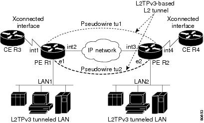
In the figure above, the PE routers R1 and R2 provide L2TPv3 services. The R1 and R2 routers communicate with each other using a pseudowire over the IP backbone network through a path comprising the interfaces int1 and int2, the IP network, and interfaces int3 and int4.
In this example, the CE routers R3 and R4 communicate through a pair of xconnect Ethernet or VLAN interfaces using an L2TPv3 session. The L2TPv3 session tu1 is a pseudowire configured between interface int1 on R1 and interface int4 on R2. Any packet arriving on interface int1 on R1 is encapsulated and sent through the pseudowire control channel (tu1) to R2. R2 decapsulates the packet and sends it on interface int4 to R4. When R4 needs to send a packet to R3, the packet follows the same path in reverse.
Note the following features regarding L2TPv3 operation:
- All packets received on interface int1 are forwarded to R4. R3 and R4 cannot detect the intervening network.
- For Ethernet interfaces, any packet received from LAN1 by R1 on Ethernet interface e1 are encapsulated directly in IP and sent through the pseudowire session tu2 to R2 interface e2, where it is sent on LAN2.
- A VLAN on an Ethernet interface can be mapped to an L2TPv3 session.
L2TPv3 Benefits
Simplifies Deployment of VPNs
L2TPv3 is an industry-standard Layer 2 tunneling protocol that ensures interoperability among vendors, thus increasing customer flexibility and service availability.
Omits the Need for MPLS
Service providers need not deploy Multiprotocol Label Switching (MPLS) in the core IP backbone to set up VPNs using L2TPv3 over the IP backbone, resulting in operational savings and increased revenue.
L2TPv3 Header Description
The migration from UTI to L2TPv3 also requires the standardization of the UTI header. As a result, the L2TPv3 header has the new format shown in the figure below.
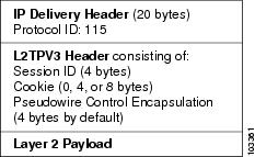
Each L2TPv3 packet contains an L2TPv3 header that includes a unique session ID representing one session and a variable cookie length. The L2TPv3 session ID and the Tunnel Cookie field length are assigned through the CLI. See the section "How to Configure L2TPv3" for more information on the CLI commands for L2TPv3.
Session ID
The L2TPv3 session ID is similar to the UTI session ID, and identifies the session context on the decapsulating system. For dynamic sessions, the value of the session ID is selected to optimize the context identification efficiency of the decapsulating system. A decapsulation implementation may therefore elect to support a smaller session ID bit field. In this L2TPv3 implementation, an upper value for the L2TPv3 session ID was set at 023. The L2TPv3 session ID value 0 is reserved for use by the protocol. For static sessions, the session ID is manually configured.
Note | The local session ID must be unique on the decapsulating system and is restricted to the least significant ten bits. |
Session Cookie
The L2TPv3 header contains a control channel cookie field that is similar to the UTI control channel key field. However, the control channel cookie field has a variable length of 0, 4, or 8 bytes according to the cookie length supported by a given platform for packet decapsulation. The control channel cookie length can be manually configured for static sessions or dynamically determined for dynamic sessions.
The variable cookie length does not present a problem when the same platform is at both ends of an L2TPv3 control channel. However, when different platforms interoperate across an L2TPv3 control channel, both platforms need to encapsulate packets with a 4-byte cookie length.
Pseudowire Control Encapsulation
The L2TPv3 pseudowire control encapsulation consists of 32 bits (4 bytes) and contains information used to sequence L2TP packets and to distinguish AAL5 data and OAM cells for AAL5 SDU mode over L2TPv3. For the purposes of sequencing, only the first bit and bits 8 to 31 are relevant. Bit 1 indicates whether the Sequence Number field, bits 8 to 31, contains a valid sequence number and is to be updated.
L2TPv3 Features
L2TPv3 provides xconnect support for Ethernet, 802.1q (VLAN), Frame Relay, HDLC, and PPP.
- Control Channel Parameters
- L2TPv3 Control Channel Authentication Parameters
- Static L2TPv3 Sessions
- Dynamic L2TPv3 Sessions
- Sequencing
- Local Switching
- Distributed Switching
- L2TPv3 Layer 2 Fragmentation
- L2TPv3 Type of Service Marking
- Keepalive
- MTU Handling
- L2TPv3 Control Message Hashing
- L2TPv3 Control Message Rate Limiting
- L2TPv3 Digest Secret Graceful Switchover
- L2TPv3 Pseudowire
- Manual Clearing of L2TPv3 Tunnels
- L2TPv3 Tunnel Management
- L2TPv3 Protocol Demultiplexing
- Color Aware Policer on Ethernet over L2TPv3
- Site of Origin for Border Gateway Protocol VPNs
- L2TPv3 Custom Ethertype for Dot1q and QinQ Encapsulations
Control Channel Parameters
The L2TP class configuration procedure creates a template of L2TP control channel parameters that can be inherited by different pseudowire classes. L2TP control channel parameters are used in control channel authentication, keepalive messages, and control channel negotiation. In an L2TPv3 session, the same L2TP class must be specified in the pseudowire configured on the PE router at each end of the control channel. Configuring L2TP control channel parameters is optional. However, the L2TP class must be configured before it is associated with a pseudowire class (see the Configuring the L2TPv3 Pseudowire task).
L2TPv3 Control Channel Authentication Parameters
Two methods of control channel message authentication are available: the L2TPv3 Control Message Hashing feature and CHAP-style L2TP control channel. The L2TPv3 Control Message Hashing feature introduces a more robust authentication method than the older, CHAP-style L2TP control channel method of authentication. You may choose to enable both the methods of authentication to ensure interoperability with peers that support only one of these methods of authentication, but this configuration will yield control of the authentication method used on the peer PE router. Enabling both the methods of authentication should be considered as an interim solution to solve backward compatibility issues during software upgrades.
The principal difference between the two methods of authentication lies in the L2TPv3 Control Message Hashing feature using the entire message in the hash instead of computing the hash over selected contents of a received control message. In addition, instead of including the hash digest in only the start control channel replay (SCCRP) and start control channel connected (SCCCN) messages, it includes it in all messages.
Support for L2TP control channel authentication is maintained for backward compatibility. Either or both authentication methods can be enabled to allow interoperability with peers supporting only one of the authentication methods.
The table below shows a compatibility matrix for the different L2TPv3 authentication methods. PE1 is running the new authentication method. The possible authentication configurations for PE1 are shown in the first column. The other columns represent PE2 running software with different available authentication options. The tables cells in these columns indicate compatible configuration options for PE2. If any PE1/PE2 authentication configuration poses ambiguity about the authentication method used, the winning authentication method is indicated in bold. If both the old and new authentication methods are enabled on PE1 and PE2, both types of authentication occur.
| Table 5 | Compatibility Matrix for L2TPv3 Authentication Methods |
|
PE1 Authentication Configuration |
PE2 Supporting Old Authentication5 |
PE2 Supporting New Authentication6 |
PE2 Supporting Old and New Authentication7 |
|---|---|---|---|
|
None |
None |
None New integrity check |
None New integrity check |
|
Old authentication |
Old authentication |
-- |
Old authentication Old authentication and new authentication Old authentication and new integrity check |
|
New authentication |
-- |
New authentication |
New authentication Old authentication and new authentication |
|
New integrity check |
None |
None New integrity check |
None New integrity check |
|
Old and new authentication |
Old authentication |
New authentication |
Old authentication New authentication Old and new authentication Old authentication and new integrity check |
|
Old authentication and new integrity check |
Old authentication |
-- |
Old authentication Old authentication and new authentication Old authentication and new integrity check |
Static L2TPv3 Sessions
Typically, the L2TP control plane is responsible for negotiating session parameters, such as the session ID or the cookie, to set up the session. However, some IP networks require sessions to be configured so that no signaling is required for session establishment. You can set up static L2TPv3 sessions for a PE router by configuring fixed values for the fields in the L2TP data header. A static L2TPv3 session allows the PE router to tunnel Layer 2 traffic as soon as the attachment circuit to which the session is bound comes up.
Static configuration allows sessions to be established without dynamically negotiating control connection parameters. This means that although sessions are displayed in the show l2tun session command output, no control channel information is displayed in the show l2tun tunnel command output.
If you use a static L2TPv3 session, you cannot perform circuit interworking, such as LMI, because there is no facility to exchange control messages. To perform circuit interworking, you must use a dynamic session.
Dynamic L2TPv3 Sessions
A dynamic L2TP session is established through the exchange of control messages containing attribute-value (AV) pairs. Each AV pair contains information about the nature of the Layer 2 link being forwarded, including the payload type and virtual circuit (VC) ID.
Multiple L2TP sessions, one for each forwarded Layer 2 circuit, can exist between a pair of PE routers and can be maintained by a single control channel. Session IDs and cookies are dynamically generated and exchanged as part of a dynamic session setup. Information such as sequencing configuration is also exchanged. Circuit state changes (UP/DOWN) are conveyed using the set link info (SLI) message.
Sequencing
Although the correct sequence of received Layer 2 frames is guaranteed by some Layer 2 technologies (by the nature of the link such as a serial line) or by the protocol itself, forwarded Layer 2 frames may be lost, duplicated, or reordered when they traverse a network as IP packets. If the Layer 2 protocol does not provide an explicit sequencing mechanism, you can configure L2TP to sequence its data packets according to the data channel sequencing mechanism described in the L2TPv3 IETF l2tpext working group draft.
A receiver of L2TP data packets mandates sequencing through the Sequencing Required AV pair when the session is being negotiated. A sender (or one that is manually configured to send sequenced packets) that receives this AV pair uses the Layer 2-specific pseudowire control encapsulation defined in L2TPv3.
You can configure L2TP to drop only out-of-order packets; you cannot configure L2TP to deliver the packets out-of-order. No reordering mechanism is available.
Interworking is not allowed when sequencing is enabled.
Local Switching
Local switching (from one port to another port in the same router) is supported for both static and dynamic sessions. You must configure separate IP addresses for each xconnect statement.
See the section "GUID-A5E30080-938F-4581-B0A2-0593CA31629B" for an example of how to configure local port switching.
Distributed Switching
Distributed CEF switching is supported for L2TP on the Cisco 7500 series routers.
Note | For the Cisco 7500 series, sequencing is supported, but all L2TP packets that require sequence number processing are sent to the RSP. |
L2TPv3 Layer 2 Fragmentation
Because the reassembly of fragmented packets is computationally expensive, it is desirable to avoid fragmentation issues in the service provider network. The easiest way to avoid fragmentation issues is to configure the CE routers with an path maximum transmission unit (MTU) value that is smaller than the pseudowire path MTU. However, in scenarios where this is not an option, fragmentation issues must be considered. L2TP initially supported only the following options for packet fragmentation when a packet is determined to exceed the L2TP path MTU:
- Unconditionally drop the packet
- Fragment the packet after L2TP/IP encapsulation
- Drop the packet and send an Internet Control Message Protocol (ICMP) unreachable message back to the CE router
The L2TPv3 Layer 2 Fragmentation feature introduces the ability to allow IP traffic from the CE router to be fragmented before the data enters the pseudowire, forcing the computationally expensive reassembly to occur in the CE network rather than in the service-provider network. The number of fragments that must be generated is determined based on the discovered pseudowire path MTU.
To enable the discovery of the path MTU for Layer 2 traffic, enter the ip pmtu command in a pseudowire class configuration (see GUID-48F43492-0A1E-44FD-8485-E82C3194E89D). On the PE router, the original Layer 2 header is then copied to each of the generated fragments, the L2TP/IP encapsulation is added, and the frames are forwarded through the L2TPv3 pseudowire.
Because the Don't Fragment (DF) bit in the Layer 2 encapsulation header is copied from the inner IP header to the encapsulation header, fragmentation of IP packets is performed on any packets received from the CE network that have a DF bit set to 0 and that exceed the L2TP path MTU in size. To prevent the reassembly of fragmented packets on the decapsulation router, you can enter the ip dfbit set command in the pseudowire class configuration to enable the DF bit in the outer Layer 2 header.
L2TPv3 Type of Service Marking
When Layer 2 traffic is tunneled across an IP network, information contained in the Type of Service (ToS) bits may be transferred to the L2TP-encapsulated IP packets in one of the following ways:
- If the tunneled Layer 2 frames themselves encapsulate IP packets, it may be desirable to simply copy the ToS bytes of the inner IP packets to the outer IP packet headers. This action is known as "ToS byte reflection."
- You can specify the ToS byte value used by all packets sent across the pseudowire. This is known as "Static ToS byte configuration".
For more details on how to configure ToS, see the Example: Configuring a Negotiated L2TPv3 Session for Local HDLC Switching section.
Keepalive
The keepalive mechanism for L2TPv3 extends only to the endpoints of the tunneling protocol. L2TP has a reliable control message delivery mechanism that serves as the basis for the keepalive mechanism. The keepalive mechanism consists of an exchange of L2TP hello messages.
If a keepalive mechanism is required, the control plane is used, although it may not be used to bring up sessions. You can configure sessions manually.
In the case of static L2TPv3 sessions, a control channel between the two L2TP peers is negotiated through the exchange of start control channel request (SCCRQ), SCCRP, and SCCCN control messages. The control channel is responsible for maintaining only the keepalive mechanism through the exchange of hello messages.
The interval between hello messages is configurable per control channel. If one peer detects that the other peer has gone down through the keepalive mechanism, it sends a StopCCN control message and then notifies all the pseudowires to the peer about the event. This notification results in the teardown of both manually configured and dynamic sessions.
MTU Handling
It is important that you configure a Maximum Transmission Unit (MTU) appropriate for each L2TPv3 tunneled link. The configured MTU size ensures the following:
- The lengths of the tunneled Layer 2 frames fall below the MTU of the destination attachment circuit.
- The tunneled packets are not fragmented, which forces the receiving PE to reassemble them.
L2TPv3 handles the MTU as follows:
- The default behavior is to fragment packets that are larger than the session MTU.
- If you enable the ip dfbit set command in the pseudowire class, the default MTU behavior changes so that any packets that cannot fit within the tunnel MTU are dropped.
- If you enable the ip pmtu command in the pseudowire class, the L2TPv3 control channel participates in the path MTU (PMTU) discovery.
If you enable this feature, the following processing is performed:
- Internet Control Message Protocol (ICMP) unreachable messages sent back to the L2TPv3 router are deciphered and the tunnel MTU is updated accordingly. To receive ICMP unreachable messages for fragmentation errors, the Don't Fragment (DF) bit in the tunnel header is either set according to the DF bit value received from the CE device or set statically if the ip dfbit set option is enabled. The tunnel MTU is periodically reset to the default value based on a periodic timer.
- ICMP unreachable messages are sent back to the clients on the CE side. ICMP unreachable messages are sent to the CE whenever IP packets arrive on the CE-PE interface and have a packet size greater than the tunnel MTU. A Layer 2 header calculation is performed before the ICMP unreachable message is sent to the CE.
L2TPv3 Control Message Hashing
The L2TPv3 Control Message Hashing feature introduces a new and more secure authentication system that replaces the CHAP-like authentication system inherited from L2TPv2, which uses the Challenge and Challenge Response AV pairs in the SCCRQ, SCCRP, and SCCCN messages. The L2TPv3 Control Message Hashing feature incorporates an optional authentication or integrity check for all control messages.
The per-message authentication introduced by the L2TPv3 Control Message Hashing feature is designed to:
- Perform a mutual authentication between L2TP nodes.
- Check integrity of all control messages.
- Guard against control message spoofing and replay attacks that would otherwise be trivial to mount against the network.
The new authentication method uses the following:
- A computed, one-way hash over the header and body of the L2TP control message
- A preconfigured, shared secret that must be defined on the communicating L2TP nodes
- A local and remote random value exchanged using the Nonce AV pairs
Received control messages that lack any of the required security elements are dropped.
L2TPv3 control message integrity checking is a unidirectional mechanism that does not require the configuration of a shared secret. If integrity checking is enabled on the local PE router, control messages are sent with the message digest calculated without the shared secret or Nonce AV pairs and are verified by the remote PE router. If verification fails, the remote PE router drops the control message.
Enabling the L2TPv3 Control Message Hashing feature will impact performance during control channel and session establishment because additional digest calculation of the full message content is required for each sent and received control message. This is an expected trade-off for the additional security provided by this feature. In addition, network congestion may occur if the receive window size is too small. If the L2TPv3 Control Message Hashing feature is enabled, message digest validation must be enabled. Message digest validation deactivates the data path received sequence number update and restricts the minimum local receive window size to 35.
You may choose to configure control channel authentication or control message integrity checking. Control channel authentication requires participation by both peers and a shared secret must be configured on both routers. Control message integrity check is unidirectional and requires configuration on only one of the peers.
L2TPv3 Control Message Rate Limiting
The L2TPv3 Control Message Rate Limiting feature was introduced to counter the possibility of a denial-of-service (DoS) attack on a router running L2TPv3. The L2TPv3 Control Message Rate Limiting feature limits the rate at which SCCRQ control packets arriving at the PE that terminates the L2TPv3 tunnel can be processed. SCCRQ control packets initiate the process of bringing up the L2TPv3 tunnel and require a large amount of control plane resources of the PE router.
No configuration is required for the L2TPv3 Control Message Rate Limiting feature. This feature automatically runs in the background in supported releases.
L2TPv3 Digest Secret Graceful Switchover
Authentication of L2TPv3 control channel messages occurs using a password that is configured on all participating peer PE routers. Before the introduction of this feature, changing this password required removing of the old password from the configuration before adding the new password, causing an interruption in L2TPv3 services. The authentication password must be updated on all peer PE routers, which are often at different physical locations. It is difficult for all peer PE routers to be updated with the new password simultaneously to minimize interruptions in L2TPv3 services.
The L2TPv3 Digest Secret Graceful Switchover feature allows the password used to authenticate L2TPv3 control channel messages to be changed without tearing down the established L2TPv3 tunnels. This feature works only for authentication passwords configured with the L2TPv3 Control Message Hashing feature. Authentication passwords configured with the older, CHAP-like authentication system cannot be updated without tearing down L2TPv3 tunnels.
The L2TPv3 Digest Secret Graceful Switchover feature allows two control channel passwords to be configured simultaneously, so a new control channel password can be enabled without first removing the old password. Established tunnels are rapidly updated with the new password, but continue to use the old password until it is removed from the configuration. This allows authentication to continue normally with peer PE routers that have not yet been updated to use the new password. After all peer PE routers are configured with the new password, the old password can be removed from the configuration.
During the period when both a new and an old password are configured, authentication will occur only with the new password if the attempt to authenticate using the old password fails.
L2TPv3 Pseudowire
The pseudowire class configuration procedure creates a configuration template for the pseudowire. Use this template or class to configure session-level parameters for L2TPv3 sessions that are used to transport attachment circuit traffic over the pseudowire.
The pseudowire configuration specifies the characteristics of the L2TPv3 signaling mechanism, including the data encapsulation type, the control protocol, sequencing, Layer 3 fragmentation, payload-specific options, and IP properties. The setting that determines whether signaling is used to set up the pseudowire is also included.
If you specify the encapsulation l2tpv3 command, you cannot remove it by using the no encapsulation l2tpv3 command. You also cannot change the command setting by using the encapsulation mpls command. These methods result in the following error message:
Encapsulation changes are not allowed on an existing pw-class.
To remove the command, you must delete the pseudowire by using the no pseudowire-class command. To change the type of encapsulation, remove the pseudowire by using the no pseudowire-class command, reestablish the pseudowire, and specify the new encapsulation type.
Manual Clearing of L2TPv3 Tunnels
This feature lets you clear L2TPv3 tunnels manually. Before the introduction of this feature, there was no provision to clear a specific L2TPv3 tunnel manually. This functionality provides users more control over an L2TPv3 network.
L2TPv3 Tunnel Management
New and enhanced commands have been introduced to facilitate the management and diagnosis of problems with xconnect configurations. No specific configuration tasks are associated with these commands.
- debug vpdn--The output of this command includes authentication failure messages.
- show l2tun session--The hostname keyword allows the peer hostname to be displayed in the output.
- show l2tun tunnel--The authentication keyword allows the display of global information about L2TP control channel authentication AV pairs.
- show xconnect--The output of this command displays information about xconnect attachment circuits and pseudowires. This command also provides a sortable, single point of reference for information about all xconnect configurations.
- xconnect logging pseudowire status--This command enables syslog reporting of pseudowire status events.
For information about these Cisco IOS commands, go to the Command Lookup Tool at http://tools.cisco.com/Support/CLILookup or to the Cisco IOS Master Commands List, All Releases.
Control Message Statistics and Conditional Debugging Command Enhancements
This feature introduces new commands and modifies existing commands for managing control message statistics and conditionally filtering xconnect debug messages.
For this feature, the following commands were introduced:
- clear l2tun counters --Clears session counters for Layer 2 tunnels.
- clear l2tun counters tunnel l2tp --Clears global or per-tunnel control message statistics.
- debug condition xconnect --Allows the conditional filtering of debug messages related to xconnect configurations (allows pseudowire conditional debugging)
- monitor l2tun counters tunnel l2tp --Enables or disables the collection of per-tunnel control message statistics.
- show l2tun counters tunnel l2tp --Displays global or per-tunnel control message statistics.
For this feature, the following command was modified:
L2TPv3 Protocol Demultiplexing
The L2TPv3 Protocol Demultiplexing feature introduces the ability to provide native IPv6 support by utilizing a specialized IPv6 network to offload IPv6 traffic from the IPv4 network. The IPv6 traffic is tunneled to the IPv6 network transparently by using L2TPv3 pseudowires without affecting the configuration of the CE routers. IPv4 traffic is routed as usual within the IPv4 network, maintaining the existing performance and reliability of the IPv4 network.
The IPv4 PE routers must be configured to demultiplex the incoming IPv6 traffic from IPv4 traffic. The PE routers facing the IPv6 network do not require the IPv6 configuration. The configuration of the IPv6 network is beyond the scope of this document. For more information on configuring an IPv6 network, see the IPv6 Configuration Guide.
Color Aware Policer on Ethernet over L2TPv3
The Color-Aware Policer enables a "color-aware" method of traffic policing. This feature allows you to police traffic according to the color classification of a packet. The packet color classification is based on packet matching criteria defined for two user-specified traffic classes--the conform-color class and the exceed-color class. These two traffic classes are created using the conform-color command and the metering rates are defined using the police command.
Site of Origin for Border Gateway Protocol VPNs
Site of Origin (SoO) for Border Gateway Protocol Virtual Private Networks (BGP-VPNs) is supported in Cisco IOS Release 12.0(33)S. Site of Origin (SoO) is a concept in a distributed VPN architecture that prevents routing loops in a site which is multi-homed to the VPN backbone and uses AS-OVERRIDE. The mechanism works by applying the SoO tag at the VPN entry point, the provider's edge (PE) equipment. When SoO is enabled, the PE only forwards prefixes to the customer premises equipment (CPE) when the SoO tag of the prefix does not match the SoO tag configured for the CPE.
Each site should be assigned a unique ID value, which is used as the second half of the SoO tag. These ID values used can be repeated for different customers, but not for the same customer. A "site" is considered SoO enabled if it has two or more CPEs that are connected to different PEs and includes at least one non-PE link between them.
SoO is a BGP extended community attribute used to identify when a prefix that originated from a customer site is re-advertised back into that site from a backdoor link. The following format can be used to address the SoO extended community:
<Customer-AS>:<Site-ID>
SoO can now be configured either using inbound route-maps or using the per-neighbor neighbor soo command. The SoO value set through the neighbor soo command should override the legacy inbound route-map settings when both are configured at the same time.
L2TPv3 Custom Ethertype for Dot1q and QinQ Encapsulations
The L2TPv3 Custom Ethertype for Dot1q and QinQ Encapsulations feature lets you configure an Ethertype other than 0x8100 on Gigabit Ethernet interfaces with the QinQ or Dot1Q encapsulation. You can set the custom Ethertype to 0x9100, 0x9200, or 0x88A8. This allows interoperability in a multivendor Gigabit Ethernet environment.
L2TPv3 and UTI Feature Comparison
The table below compares L2TPv3 and UTI feature support for the Cisco 7200 and Cisco 7500 series routers.
| Table 6 | Comparison of L2TPv3 and UTI Feature Support |
|
Feature |
L2TPv3 |
UTI |
|---|---|---|
|
Maximum number of sessions |
Cisco 7200 and Cisco 7500 series:3000 |
Cisco 7200 and Cisco 7500 series: 1000 |
|
Tunnel cookie length |
0-, 4-, or 8-byte cookies are supported for the Cisco 7200 series and the Cisco 7500 series routers. |
8 bytes |
|
Static sessions |
Supported in Cisco IOS Release 12.0(21)S. |
Supported |
|
Dynamic sessions |
Supported in Cisco IOS Release 12.0(23)S. |
Not supported |
|
Static ToS |
Supported in Cisco IOS Release 12.0(23)S. |
Supported |
|
MQC ToS |
Supported in Cisco IOS Release 12.0(27)S. |
Supported |
|
Inner IP ToS mapping |
Supported on the Cisco 7200 series routers and Cisco 7500 series routers. |
Not supported |
|
802.1p mapping |
Not supported. |
Not supported |
|
Keepalive |
Supported in Cisco IOS Release 12.0(23)S. |
Not supported |
|
Path MTU discovery |
Supported on the Cisco 7200 series and Cisco 7500 series routers. |
Not supported |
|
ICMP unreachable |
Supported on the Cisco 7200 series and Cisco 7500 series routers. |
Not supported |
|
VLAN rewrite |
Supported on the Cisco 7200 series and Cisco 7500 series routers in Cisco IOS Release 12.0(23)S. |
Supported |
|
VLAN and non-VLAN translation |
To be supported in a future release. |
Not supported |
|
Port trunking |
Supported in Cisco IOS Release 12.0(23)S. |
Supported |
|
IS-IS packet fragmentation through an L2TPv3 session |
Supported on the Cisco 7200 series and Cisco 7500 series routers, and on the Cisco 10720 Internet router in Cisco IOS Release 12.0(24)S. |
Not supported |
|
L2TPv3 Layer 2 (IP packet) fragmentation through an L2TPv3 session |
Supported on the Cisco 7200 series and Cisco 7500 series routers in Cisco IOS Release 12.0(24)S. Supported on the Cisco 10720 Internet router in Cisco IOS Release 12.0(32)SY. |
Not supported |
|
Payload sequence number checking |
Supported on the Cisco 7500 series in Cisco IOS Release 12.0(28)S. |
Not supported |
|
MIB support |
IfTable MIB for the attachment circuit. |
IfTable MIB for the session interface. |
Supported L2TPv3 Payloads
Note | Each L2TPv3 tunneled packet includes the entire Layer 2 frame of the payloads described in this section. If sequencing is required (see the Sequencing section), a Layer 2-specific sublayer (see the Pseudowire Control Encapsulation section) is included in the L2TPv3 header to provide the Sequence Number field. |
Frame Relay
- Port-to-Port Trunking
- DLCI-to-DLCI Switching
- PVC Status Signaling
- Sequencing
- ToS Marking
- CIR Guarantees
- Binding L2TPv3 Sessions to Multilink Frame Relay Interfaces
Port-to-Port Trunking
Port-to-port trunking is where two CE Frame Relay interfaces are connected as by a leased line (UTI raw mode). All traffic arriving on one interface is forwarded transparently across the pseudowire to the other interface.
For example, in Figure 1 , if the two CE routers are connected by a virtual leased line, the PE routers transparently transport all packets between CE R3 and CE R4 over a pseudowire. PE R1 and PE R2 do not examine or change the DLCIs, and do not participate in the LMI protocol. The two CE routers are LMI peers. There is nothing Frame Relay-specific about this service as far as the PE routers are concerned. The CE routers should be able to use any encapsulation based on HDLC framing without needing to change the provider configuration.
DLCI-to-DLCI Switching
Frame Relay DLCI-to-DLCI switching is where individual Frame Relay DLCIs are connected to create an end-to-end Frame Relay PVC. Traffic arriving on a DLCI on one interface is forwarded across the pseudowire to another DLCI on the other interface.
For example, in Figure 1 , CE R3 and PE R1 are Frame Relay LMI peers; CE R4 and PE R2 are also LMI peers. You can use a different type of LMI between CE R3 and PE R1 compared to what you use between CE R4 and PE R2.
The CE devices may be a Frame Relay switch or end-user device. Each Frame Relay PVC is composed of multiple segments. The DLCI value is local to each segment and is changed as traffic is switched from segment to segment. Note that, in Figure 1 , two Frame Relay PVC segments are connected by a pseudowire. Frame Relay header flags (FECN, BECN, C/R, DE) are preserved across the pseudowire.
PVC Status Signaling
PVC status signaling is propagated toward Frame Relay end users by the LMI protocol. You can configure the LMI to operate in any of the following modes:
- UNI DTE mode--PVC status is not reported, only received.
- UNI DCE mode--PVC status is reported but not received.
- NNI mode--PVC status is reported and received independently.
L2TPv3 supports all three modes.
The PVC status should be reported as ACTIVE only if the PVC is available from the reporting device to the Frame Relay end-user device. All interfaces, line protocols, and pseudowires must be operational between the reporting device and the Frame Relay end-user device.
Note that any keepalive functions on the session are independent of Frame Relay, but any state changes that are detected are fed into the PVC status reporting. For example, the L2TP control channel uses hello packets as a keepalive function. If the L2TPv3 keepalive fails, all L2TPv3 sessions are torn down. Loss of the session is notified to Frame Relay, which can then report PVCs INACTIVE to the CE devices.
For example, in Figure 1 , CE R3 reports ACTIVE to PE R1 only if the PVC is available within CE R3. When CE R3 is a switch, it reports all the way to the user device in the customer network.
PE R1 reports ACTIVE to CE R3 only if the PVC is available within PE R1 and all the way to the end-user device (through PE R2 and CE R3) in the other customer VPN site.
The ACTIVE state is propagated hop-by-hop, independently in each direction, from one end of the Frame Relay network to the other end.
Sequencing
Frame Relay provides an ordered service in which packets sent to the Frame Relay network by one end-user device are delivered in order to the other end-user device. When switching is occurring over the pseudowire, packet ordering must be able to be preserved with a very high probability to closely emulate a traditional Frame Relay service. If the CE router is not using a protocol that can detect misordering itself, configuring sequence number processing may be important. For example, if the Layer 3 protocol is IP and Frame Relay is therefore used only for encapsulation, sequencing is not required. To detect misordering, you can configure sequence number processing separately for transmission or reception. For more information about how to configure sequencing, see the section "Configuring a Negotiated L2TPv3 Session for Local HDLC Switching Example."
ToS Marking
The ToS bytes in the IP header can be statically configured or reflected from the internal IP header. The Frame Relay discard eligible (DE) bit does not influence the ToS bytes.
CIR Guarantees
To provide committed information rate (CIR) guarantees, you can configure a queueing policy that provides bandwidth to each DLCI to the interface facing the customer network on the egress PE.
Binding L2TPv3 Sessions to Multilink Frame Relay Interfaces
The configuration of an L2TPv3 session on a Multilink Frame Relay (MLFR) bundle interface is supported only on Cisco 12000 series 2-port channelized OC-3/STM-1 (DS1/E1) and 6-port channelized T3 (T1) line cards.
The Multilink Frame Relay feature introduces functionality based on the Frame Relay Forum Multilink Frame Relay UNI/NNI Implementation Agreement (FRF.16). This feature provides a cost-effective way to increase bandwidth for particular applications by enabling multiple serial links to be aggregated into a single bundle of bandwidth.
For an example of how to configure L2TPv3 tunneling on a multilink Frame Relay bundle interface, see Configuring MLFR for L2TPv3 on the Cisco 12000 Series Example.
For information about how configure and use the MLFR feature, refer to the Multilink Frame Relay (FRF.16) publication .
Ethernet
An Ethernet frame arriving at a PE router is simply encapsulated in its entirety with an L2TP data header. At the other end, a received L2TP data packet is stripped of its L2TP data header. The payload, an Ethernet frame, is then forwarded to the appropriate attachment circuit.
Because the L2TPv3 tunneling protocol serves essentially as a bridge, it need not examine any part of an Ethernet frame. Any Ethernet frame received on an interface is tunneled, and any L2TP-tunneled Ethernet frame is forwarded out of the interface.
VLAN
L2TPv3 supports VLAN memberships in the following ways:
- Port-based, in which undated Ethernet frames are received
- VLAN-based, in which tagged Ethernet frames are received
In L2TPv3, Ethernet xconnect supports port-based VLAN membership and the reception of tagged Ethernet frames. A tagged Ethernet frame contains a tag header (defined in 802.1Q), which is 4 bytes long and consists of a 2-byte tag protocol identifier (TPID) field and a 2-byte tag control information (TCI) field. The TPID indicates that a TCI follows. The TCI is further broken down into the following three fields:
For L2TPv3, an Ethernet subinterface configured to support VLAN switching may be bound to an xconnect service so that all Ethernet traffic, tagged with a VID specified on the subinterface, is tunneled to another PE. The VLAN Ethernet frames are forwarded in their entirety. The receiving PE may rewrite the VID of the tunneled traffic to another value before forwarding the traffic onto an attachment circuit.
To successfully rewrite VLANs, it may be necessary to disable the Spanning Tree Protocol (STP). This can be done on a per-VLAN basis by using the no spanning-tree vlan command.
HDLC
L2TPv3 encapsulates an HDLC frame arriving at a PE in its entirety (including the Address, Control, and Protocol fields, but not the Flag fields and the frame check sequence) with an L2TP data header.
PPP
PEs that support L2TPv3 forward PPP traffic using a "transparent pass-through" model, in which the PEs play no role in the negotiation and maintenance of the PPP link. L2TPv3 encapsulates a PPP frame arriving at a PE in its entirety (including the HDLC Address and Control fields) with an L2TP data header.
ATM
L2TPv3 can connect two isolated ATM clouds over a packet-switched network (PSN) while maintaining an end-to-end ATM Service Level Agreement (SLA). The ATM Single Cell Relay features forward one ATM cell per packet. The ATM Cell Packing over L2TPv3 features allows multiple ATM frames to be packed into a single L2TPv3 data packet. All packets are transparently forwarded over the L2TPv3 pseudowire.
The table below shows the releases that introduced support for the ATM cell relay features.
- ATM Single Cell Relay VC Mode over L2TPv3
- ATM VP Mode Single Cell Relay over L2TPv3
- ATM Port Mode Cell Relay over L2TPv3
- ATM Cell Packing over L2TPv3
- ATM AAL5 over L2TPv3
ATM Single Cell Relay VC Mode over L2TPv3
The ATM Single Cell Relay VC mode over L2TPv3 feature maps one VC to a single L2TPv3 session. All ATM cells arriving at an ATM interface with the specified VPI and VCI are encapsulated into a single L2TP packet. Each ATM cell will have a 4-byte ATM cell header without Header Error Control Checksum (HEC) and a 48-byte ATM cell payload.
The ATM Single Cell Relay VC mode feature can be used to carry any type of AAL traffic over the pseudowire. It will not distinguish OAM cells from User data cells. In this mode, Performance and Security OAM cells are also transported over the pseudowire.
ATM VP Mode Single Cell Relay over L2TPv3
The ATM VP Mode Single Cell Relay over L2TPv3 feature allows cells coming into a predefined PVP on the ATM interface to be transported over an L2TPv3 pseudowire to a predefined PVP on the egress ATM interface. A single ATM cell is encapsulated into each L2TPv3 data packet.
ATM Port Mode Cell Relay over L2TPv3
The ATM Port Mode Cell Relay over L2TPv3 feature packs ATM cells arriving at an ingress ATM interface into L2TPv3 data packets and transports them to the egress ATM interface. A single ATM cell is encapsulated into each L2TPv3 data packet.
ATM Cell Packing over L2TPv3
The ATM Cell Packing over L2TPv3 feature enhances throughput and uses bandwidth more efficiently than the ATM cell relay features. Instead of a single ATM cell being packed into each L2TPv3 data packet, multiple ATM cells can be packed into a single L2TPv3 data packet. ATM cell packing is supported for Port mode, VP mode, and VC mode. Cell packing must be configured on the PE devices. No configuration is required on the CE devices.
ATM AAL5 over L2TPv3
The ATM AAL5 over L2TPv3 feature maps the AAL5 payload of an AAL5 PVC to a single L2TPv3 session. This service will transport OAM and RM cells, but does not attempt to maintain the relative order of these cells with respect to the cells that comprise the AAL5 common part convergence sublayer protocol data unit (CPCS-PDU). OAM cells that arrive during the reassembly of a single AAL5 CPCS-PDU are sent immediately over the pseudowire, followed by the AAL5 payload without the AAL5 pad and trailer bytes.
VC Class Provisioning for L2TPv3
Beginning in Cisco IOS Release 12.0(30)S, ATM AAL5 encapsulation over L2TPv3 can be configured in VC class configuration mode in addition to ATM VC configuration mode. The ability to configure ATM encapsulation parameters in VC class configuration mode provides greater control and flexibility for AAL5 encapsulation configurations.
OAM Transparent Mode
In OAM transparent mode, the PEs will pass the following OAM cells transparently across the pseudowire:
- F5 segment and end-to-end Fault Management (FM) OAM cells
- RM OAM cells, except Performance Management (PM) and Security OAM cells
Note | The Cisco 7200 and the Cisco 7500 ATM driver cannot forward RM cells over the PSN for ABR ToS. The RM cells are locally terminated. |
VPI or VPI/VCI rewrite is not supported for any ATM transport mode. Both pairs of PE to CE peer routers must be configured with matching VPI and VCI values except in OAM local emulation mode. For example, if PE1 and CE1 are connected by PVC 10/100, PE2 and CE2 should also be connected by PVC 10/100.
OAM Local Emulation Mode
In OAM Local Emulation mode, OAM cells are not passed through the pseudowire. All F5 OAM cells are terminated and handled locally. On the L2TPv3-based pseudowire, the CE device sends an SLI message across the pseudowire to notify the peer PE node about the defect, rather than tearing down the session. The defect can occur at any point in the link between the local CE and the PE. OAM management can also be enabled on the PE node using existing OAM management configurations.
IPv6 Protocol Demultiplexing
Upgrading a service provider network to support IPv6 is a long and expensive process. As an interim solution, the Protocol Demultiplexing for L2TPv3 feature introduces the ability to provide native IPv6 support by setting up a specialized IPv6 network and offloading IPv6 traffic from the IPv4 network. IPv6 traffic is tunneled transparently to the IPv6 network using L2TPv3 pseudowires without affecting the configuration of the CE routers. IPv4 traffic is routed as usual within the IPv4 network, maintaining the existing performance and reliability of the IPv4 network.
The figure below shows a network deployment that offloads IPv6 traffic from the IPv4 network to a specialized IPv6 network. The PE routers demultiplex the IPv6 traffic from the IPv4 traffic. IPv6 traffic is routed to the IPv6 network over an L2TPv3 pseudowire, while IPv4 traffic is routed normally. The IPv4 PE routers must be configured to demultiplex the incoming IPv6 traffic from the IPv4 traffic. The PE routers facing the IPv6 network do not require the IPv6 configuration.
If no IP address is configured, the protocol demultiplexing configuration is rejected. If an IP address is configured, the xconnect command configuration is rejected unless protocol demultiplexing is enabled in xconnect configuration mode before exiting that mode. If an IP address is configured with an xconnect command configuration and protocol demultiplexing is enabled, the IP address cannot be removed. To change or remove the configured IP address, the xconnect command configuration must first be disabled.
The table below shows the valid combinations of configurations.
Supported Port Adapters for the Cisco 7200 Series and Cisco 7500 Series Routers
The following port adapters support L2TPv3 on the Cisco 7200 series and Cisco 7500 series routers:
- Single-port Fast Ethernet 100BASE-TX
- Single-port Fast Ethernet 100BASE-FX
- Dual-port Fast Ethernet 100BASE-TX
- Dual-port Fast Ethernet 100BASE-FX
- Gigabit Ethernet port adapter
- 12-port Ethernet/2-port FE adapter
- 4-port synchronous serial port adapter
- Enhanced 4-port synchronous serial port adapter
- 8-port synchronous serial port adapter
- Single-port HSSI adapter
- Dual-port HSSI adapter
- Single-port enhanced OC-3 ATM port adapter
- 8-port multichannel E1 G.703/G.704 120-ohm interfaces
- 2-port multichannel E1 G.703/G.704 120-ohm interfaces
- 8-port multichannel T1 with integrated data service units (DSUs)
- 8-port multichannel T1 with integrated channel service units (CSUs) and DSUs
- 4-port multichannel T1 with integrated CSUs and DSUs
- 2-port multichannel T1 with integrated CSUs and DSUs
- 8-port multichannel T1/E1
- 1-port multichannel T3 interface
- 1-port multichannel E3 interface
- 2-port enhanced multichannel T3 port adapter
- Single-port T3 port adapter
- Single-port E3 port adapter
- 2-port T3 port adapter
- 2-port T3 port adapter
- Single-port Packet over SONET (PoS), single-mode, long reach
- Single-port PoS, single-mode, intermediate reach
- Single-port PoS, multimode
- Eight-port T1 ATM port adapter with inverse multiplexing over ATM (IMA)
- Eight-port E1 ATM port adapter with IMA
The following port adapters support L2TPv3 on the Cisco 7200 series routers only:
- 8-port Ethernet adapter
- 4-port Ethernet adapter
How to Configure L2TPv3
- Configuring L2TP Control Channel Parameters
- Configuring the L2TPv3 Pseudowire
- Configuring the Xconnect Attachment Circuit
- Manually Configuring L2TPv3 Session Parameters
- Configuring the Xconnect Attachment Circuit for ATM VP Mode Single Cell Relay over L2TPv3
- Configuring the Xconnect Attachment Circuit for ATM Single Cell Relay VC Mode over L2TPv3
- Configuring the Xconnect Attachment Circuit for ATM Port Mode Cell Relay over L2TPv3
- Configuring the Xconnect Attachment Circuit for ATM Cell Packing over L2TPv3
- Configuring the Xconnect Attachment Circuit for ATM AAL5 SDU Mode over L2TPv3
- Configuring OAM Local Emulation for ATM AAL5 over L2TPv3
- Configuring Protocol Demultiplexing for L2TPv3
- Configuring an L2TPv3 Custom Ethertype for Dot1q and QinQ Encapsulations
- Manually Clearing L2TPv3 Tunnels
Configuring L2TP Control Channel Parameters
After you enter L2TP class configuration mode, you can configure L2TP control channel parameters in any order. If you have multiple authentication requirements, you can configure multiple sets of L2TP class control channel parameters with different L2TP class names. However, only one set of parameters can be applied to a connection between any pair of IP addresses.
- Configuring L2TP Control Channel Timing Parameters
- Configuring L2TPv3 Control Channel Authentication Parameters
- Configuring L2TP Control Channel Maintenance Parameters
Configuring L2TP Control Channel Timing Parameters
The following L2TP control channel timing parameters can be configured in L2TP class configuration mode:
- Packet size of the receive window used for the control channel
- Retransmission parameters used for control messages
- Timeout parameters used for the control channel
This task configures a set of timing control channel parameters in an L2TP class. All of the timing control channel parameter configurations are optional and may be configured in any order. If these parameters are not configured, the default values are applied.
DETAILED STEPS
Configuring L2TPv3 Control Channel Authentication Parameters
- Configuring Authentication for the L2TP Control Channel
- Configuring L2TPv3 Control Message Hashing
- Configuring L2TPv3 Digest Secret Graceful Switchover
Configuring Authentication for the L2TP Control Channel
The L2TP control channel method of authentication is the older, CHAP-like authentication system inherited from L2TPv2.
The following L2TP control channel authentication parameters can be configured in L2TP class configuration mode:
- Authentication for the L2TP control channel
- Password used for L2TP control channel authentication
- Local hostname used for authenticating the control channel
This task configures a set of authentication control channel parameters in an L2TP class. All of the authentication control channel parameter configurations are optional and may be configured in any order. If these parameters are not configured, default values are applied.
DETAILED STEPS
Configuring L2TPv3 Control Message Hashing
DETAILED STEPS
| Command or Action | Purpose | |||
|---|---|---|---|---|
Step 1 |
enable
Example: Router> enable |
Enables privileged EXEC mode. | ||
Step 2 |
configure
terminal
Example: Router# configure terminal |
Enters global configuration mode. | ||
Step 3 |
l2tp-class
[l2tp-class-name]
Example: Router(config)# l2tp-class class1 |
Specifies the L2TP class name and enters L2TP class configuration mode. | ||
Step 4 |
digest
[secret [0 |
7]
password] [hash {md5 |
sha}]
Example: Router(config-l2tp-class)# digest secret cisco hash sha |
(Optional) Enables L2TPv3 control channel authentication or integrity checking.
The default hash function is md5. | ||
Step 5 |
digest
check
Example: Router(config-l2tp-class)# digest check |
(Optional) Enables the validation of the message digest in received control messages. | ||
Step 6 |
hidden
Example: Router(config-l2tp-class)# hidden |
(Optional) Enables AV pair hiding when sending control messages to an L2TPv3 peer.
| ||
Step 7 |
exit
Example: Router(config-l2tp-class)# exit |
Exits L2TP class configuration mode. |
Configuring L2TPv3 Digest Secret Graceful Switchover
Perform this task to make the transition from an old L2TPv3 control channel authentication password to a new L2TPv3 control channel authentication password without disrupting established L2TPv3 tunnels.
Before performing this task, you must enable control channel authentication as documented in the Configuring L2TPv3 Control Message Hashing task.
Note | This task is not compatible with authentication passwords configured with the older, CHAP-like control channel authentication system. |
DETAILED STEPS
| Command or Action | Purpose | |||
|---|---|---|---|---|
Step 1 |
enable
Example: Router> enable |
Enables privileged EXEC mode. | ||
Step 2 |
configure
terminal
Example: Router# configure terminal |
Enters global configuration mode. | ||
Step 3 |
l2tp-class
l2tp-class-name
Example: Router(config)# l2tp-class class1 |
Specifies the L2TP class name and enters L2TP class configuration mode. | ||
Step 4 |
digest
[secret [0 |
7]
password] [hash {md5 |
sha}]
Example: Router(config-l2tp-class)# digest secret cisco2 hash sha |
Configures a new password to be used in L2TPv3 control channel authentication.
| ||
Step 5 |
end
Example: Router(config-l2tp-class)# end |
Ends your configuration session by exiting to privileged EXEC mode. | ||
Step 6 |
show
l2tun
tunnel
all
Example: Router# show l2tun tunnel all |
(Optional) Displays the current state of Layer 2 tunnels and information about configured tunnels, including local and remote L2TP hostnames, aggregate packet counts, and control channel information.
| ||
Step 7 |
configure
terminal
Example: Router# configure terminal |
Enters global configuration mode. | ||
Step 8 |
l2tp-class
[l2tp-class-name]
Example: Router(config)# l2tp-class class1 |
Specifies the L2TP class name and enters L2TP class configuration mode. | ||
Step 9 |
no
digest
[secret [0 |
7]
password [hash {md5 |
sha}]
Example: Router(config-l2tp-class)# no digest secret cisco hash sha |
Removes the old password used in L2TPv3 control channel authentication.
| ||
Step 10 |
end
Example: Router(config-l2tp-class)# end |
Ends your configuration session by exiting to privileged EXEC mode. | ||
Step 11 |
show
l2tun
tunnel
all
Example: Router# show l2tun tunnel all |
(Optional) Displays the current state of Layer 2 tunnels and information about configured tunnels, including local and remote L2TP hostnames, aggregate packet counts, and control channel information.
|
Configuring L2TP Control Channel Maintenance Parameters
The L2TP hello packet keepalive interval control channel maintenance parameter can be configured in L2TP class configuration mode.
This task configures the interval used for hello messages in an L2TP class. This control channel parameter configuration is optional. If this parameter is not configured, the default value is applied.
DETAILED STEPS
Configuring the L2TPv3 Pseudowire
DETAILED STEPS
| Command or Action | Purpose | |||
|---|---|---|---|---|
Step 1 |
enable
Example: Router> enable |
Enables privileged EXEC mode. | ||
Step 2 |
configure
terminal
Example: Router# configure terminal |
Enters global configuration mode. | ||
Step 3 |
pseudowire-class
[pw-class-name]
Example: Router(config)# pseudowire-class etherpw |
Enters pseudowire class configuration mode and optionally specifies the name of the L2TP pseudowire class. | ||
Step 4 |
encapsulation
l2tpv3
Example: Router(config-pw)# encapsulation l2tpv3 |
Specifies that L2TPv3 is used as the data encapsulation method to tunnel IP traffic. | ||
Step 5 |
protocol
{l2tpv3
|
none}[l2tp-class-name]
Example: Router(config-pw)# protocol l2tpv3 class1 |
(Optional) Specifies the L2TPv3 signaling protocol to be used to manage the pseudowires created with the control channel parameters in the specified L2TP class (see the Configuring L2TP Control Channel Parameters task). | ||
Step 6 |
ip
local
interface
interface-name
Example: Router(config-pw)# ip local interface e0/0 |
Specifies the PE router interface whose IP address is to be used as the source IP address for sending tunneled packets.
| ||
Step 7 |
ip
pmtu
Example: Router(config-pw)# ip pmtu |
(Optional) Enables the discovery of the PMTU for tunneled traffic and helps fragmentation.
| ||
Step 8 |
ip
tos
{value
value |
reflect}
Example: Router(config-pw)# ip tos reflect |
(Optional) Configures the value of the ToS byte in IP headers of tunneled packets, or reflects the ToS byte value from the inner IP header. | ||
Step 9 |
ip
dfbit
set
Example: Router(config-pw)# ip dfbit set | (Optional) Configures the value of the DF bit in the outer headers of tunneled packets. | ||
Step 10 |
ip
ttl
value
Example: Router(config-pw)# ip ttl 100 |
(Optional) Configures the value of the time to live (TTL) byte in the IP headers of tunneled packets. | ||
Step 11 |
ip
protocol
{l2tp |
protocol-number}
Example: Router(config-pw)# ip protocol l2tp |
(Optional) Configures the IP protocol to be used for tunneling packets. | ||
Step 12 |
sequencing
{transmit |
receive |
both}
Example: Router(config-pw)# sequencing both |
(Optional) Specifies the direction in which sequencing of data packets in a pseudowire is enabled:
| ||
Step 13 |
exit
Example: Router(config-pw)# exit |
Exits pseudowire class configuration mode. |
Configuring the Xconnect Attachment Circuit
The virtual circuit identifier that you configure creates the binding between a pseudowire configured on a PE router and an attachment circuit in a CE device. The virtual circuit identifier configured on the PE router at one end of the L2TPv3 control channel must also be configured on the peer PE router at the other end.
DETAILED STEPS
| Command or Action | Purpose | |||||
|---|---|---|---|---|---|---|
Step 1 |
enable
Example: Router> enable |
Enables privileged EXEC mode. | ||||
Step 2 |
configure
terminal
Example: Router# configure terminal |
Enters global configuration mode. | ||||
Step 3 |
interface
type
slot
/
port
Example: Router(config)# interface ethernet 0/0 |
Specifies the interface by type (for example, Ethernet), slot, and port number, and enters interface configuration mode. | ||||
Step 4 |
xconnect
peer-ip-address
vcid
pseudowire-parameters
[sequencing {transmit |
receive |
both}]
Example: Router(config-if)# xconnect 10.0.3.201 123 pw-class vlan-xconnect |
Specifies the IP address of the peer PE router and the 32-bit virtual circuit identifier shared between the PE at each end of the control channel.
| ||||
Step 5 |
exit
Example: Router(config-if)# exit |
Exits interface configuration mode. |
Manually Configuring L2TPv3 Session Parameters
When you bind an attachment circuit to an L2TPv3 pseudowire for the xconnect service by using the xconnect l2tpv3 manual command (see the Configuring the Xconnect Attachment Circuit task) because you do not want signaling, you must configure L2TP-specific parameters to complete the L2TPv3 control channel configuration.
DETAILED STEPS
| Command or Action | Purpose | |
|---|---|---|
Step 1 |
enable
Example: Router> enable |
Enables privileged EXEC mode. |
Step 2 |
configure
terminal
Example: Router# configure terminal |
Enters global configuration mode. |
Step 3 |
interface
type
slot
/
port
Example: Router(config)# interface ethernet 0/0 |
Specifies the interface by type (for example, Ethernet), slot, and port number, and enters interface configuration mode. |
Step 4 |
xconnect
peer-ip-address
vc-id
encapsulation
l2tpv3
manual
pw-class
pw-class-name
Example: Router(config-if)# xconnect 10.0.3.201 123 encapsulation l2tpv3 manual pw-class vlan-xconnect |
Specifies the IP address of the peer PE router and the 32-bit virtual circuit identifier shared between the PE at each end of the control channel, and enters xconnect configuration mode.
|
Step 5 |
l2tp
id
local-session-id
remote-session-id
Example: Router(config-if-xconn)# l2tp id 222 111 |
Configures the identifiers for the local L2TPv3 session and for the remote L2TPv3 session on the peer PE router. |
Step 6 |
l2tp
cookie
local
size
low-value
[high-value]
Example: Router(config-if-xconn)# l2tp cookie local 4 54321 |
(Optional) Specifies the value that the peer PE must include in the cookie field of incoming (received) L2TP packets. |
Step 7 |
l2tp
cookie
remote
size
low-value
[high-value]
Example: Router(config-if-xconn)# l2tp cookie remote 4 12345 |
(Optional) Specifies the value that the router includes in the cookie field of outgoing (sent) L2TP packets. |
Step 8 |
l2tp
hello
l2tp-class-name
Example: Router(config-if-xconn)# l2tp hello l2tp-defaults |
(Optional) Specifies the L2TP class name to be used (see the Configuring L2TP Control Channel Parameters task) for control channel configuration parameters, including the interval to use between hello keepalive messages. |
Step 9 |
exit
Example: Router(config-if-xconn)# exit |
Exits xconnect configuration mode. |
Step 10 |
exit
Example: Router(config-if)# exit |
Exits interface configuration mode. |
Configuring the Xconnect Attachment Circuit for ATM VP Mode Single Cell Relay over L2TPv3
The ATM VP Mode Single Cell Relay over L2TPv3 feature allows cells coming into a predefined PVP on the ATM interface to be transported over an L2TPv3 pseudowire to a predefined PVP on the egress ATM interface. This task binds a PVP to an L2TPv3 pseudowire for xconnect service.
DETAILED STEPS
Configuring the Xconnect Attachment Circuit for ATM Single Cell Relay VC Mode over L2TPv3
The ATM Single Cell Relay VC Mode over L2TPv3 feature maps one VCC to a single L2TPv3 session. All ATM cells arriving at an ATM interface with the specified VPI and VCI are encapsulated into a single L2TP packet.
The ATM Single Cell Relay VC mode feature can be used to carry any type of AAL traffic over the pseudowire. It will not distinguish OAM cells from User data cells. In this mode, PM and Security OAM cells are also transported over the pseudowire.
Perform this task to enable the ATM Single Cell Relay VC Mode over L2TPv3 feature.
DETAILED STEPS
Configuring the Xconnect Attachment Circuit for ATM Port Mode Cell Relay over L2TPv3
The ATM Port Mode Cell Relay feature packs ATM cells arriving at an ingress ATM interface into L2TPv3 data packets and transports them to the egress ATM interface. A single ATM cell is encapsulated into each L2TPv3 data packet.
Perform this task to enable the ATM Port Mode Cell Relay over L2TPv3 feature.
DETAILED STEPS
| Command or Action | Purpose | |||
|---|---|---|---|---|
Step 1 |
enable
Example: Router> enable |
Enables privileged EXEC mode.
| ||
Step 2 |
configure
terminal
Example: Router# configure terminal |
Enters global configuration mode. | ||
Step 3 |
interface
type
slot
/
port
Example: Router(config)# interface ATM 4/1 |
Specifies the interface by type, slot, and port number, and enters interface configuration mode. | ||
Step 4 |
xconnect
peer-ip-address
vcid
pw-class
pw-class-name
Example: Router(config-if)# xconnect 10.0.3.201 888 pw-class atm-xconnect |
Specifies the IP address of the peer PE router and the 32-bit VCI shared between the PE at each end of the control channel.
|
Configuring the Xconnect Attachment Circuit for ATM Cell Packing over L2TPv3
The ATM Cell Packing over L2TPv3 feature allows multiple ATM frames to be packed into a single L2TPv3 data packet. ATM cell packing can be configured for Port mode, VP mode, and VC mode. Perform one of the following tasks to configure the ATM Cell Packing over L2TPv3 feature:
- Configuring Port Mode ATM Cell Packing over L2TPv3
- Configuring VP Mode ATM Cell Packing over L2TPv3
- Configuring VC Mode ATM Cell Packing over L2TPv3
Configuring Port Mode ATM Cell Packing over L2TPv3
DETAILED STEPS
| Command or Action | Purpose | |
|---|---|---|
Step 1 |
enable
Example: Router> enable |
Enables privileged EXEC mode.
|
Step 2 |
configure
terminal
Example: Router# configure terminal |
Enters global configuration mode. |
Step 3 |
interface
type
slot
/
port
Example: Router(config)# interface ATM 4/1 |
Specifies the interface by type, slot, and port number, and enters interface configuration mode. |
Step 4 |
atm
mcpt-timers
[timeout-value-1
timeout-value-2
timeout-value-3]
Example: Router(config-if)# atm mcpt-timers 10 100 1000 |
(Optional) Sets up the cell-packing timers, which specify how long the PE router can wait for cells to be packed into an L2TPv3 packet. |
Step 5 |
cell-packing
[cells] [mcpt-timer
timer]
Example: Router(config-if)# cell-packing 10 mcpt-timer 2 |
Enables the packing of multiple ATM cells into each L2TPv3 data packet.
|
Step 6 |
xconnect
peer-ip-address
vcid
pseudowire-parameters
[sequencing {transmit |
receive |
both}]
Example: Router(config-if)# xconnect 10.0.3.201 888 encapsulation l2tpv3 |
Binds an attachment circuit to a Layer 2 pseudowire and enters xconnect configuration mode. |
Configuring VP Mode ATM Cell Packing over L2TPv3
DETAILED STEPS
| Command or Action | Purpose | |
|---|---|---|
Step 1 |
enable
Example: Router> enable |
Enables privileged EXEC mode.
|
Step 2 |
configure
terminal
Example: Router# configure terminal |
Enters global configuration mode. |
Step 3 |
interface
type
slot
/
port
Example: Router(config)# interface ATM 4/1 |
Specifies the interface by type, slot, and port number, and enters interface configuration mode. |
Step 4 |
atm
mcpt-timers
[timeout-value-1
timeout-value-2
timeout-value-3]
Example: Router(config-if)# atm mcpt-timers 10 100 1000 |
(Optional) Sets up the cell-packing timers, which specify how long the PE router can wait for cells to be packed into an L2TPv3 packet. |
Step 5 |
atm
pvp
vpi
[peak-rate] [l2transport]
Example: Router(config-if)# atm pvp 10 l2transport |
Create a PVP used to multiplex (or bundle) one or more VCs. |
Step 6 |
cell-packing
[cells] [mcpt-timer
timer]
Example: Router(config-if)# cell-packing 10 mcpt-timer 2 |
Enables the packing of multiple ATM cells into each L2TPv3 data packet.
|
Step 7 |
xconnect
peer-ip-address
vcid
pseudowire-parameters
[sequencing {transmit |
receive |
both}]
Example: Router(config-if)# xconnect 10.0.3.201 888 encapsulation l2tpv3 |
Binds an attachment circuit to a Layer 2 pseudowire and enters xconnect configuration mode. |
Configuring VC Mode ATM Cell Packing over L2TPv3
DETAILED STEPS
| Command or Action | Purpose | |
|---|---|---|
Step 1 |
enable
Example: Router> enable |
Enables privileged EXEC mode.
|
Step 2 |
configure
terminal
Example: Router# configure terminal |
Enters global configuration mode. |
Step 3 |
interface
type
slot
/
port
Example: Router(config)# interface ATM 4/1 |
Specifies the interface by type, slot, and port number, and enters interface configuration mode. |
Step 4 |
atm
mcpt-timers
[timeout-value-1
timeout-value-2
timeout-value-3]
Example: Router(config-if)# atm mcpt-timers 10 100 1000 |
(Optional) Sets up the cell-packing timers, which specify how long the PE router can wait for cells to be packed into an L2TPv3 packet. |
Step 5 |
pvc
[name]
vpi
/
vci [ces |
ilmi |
qsaal |
smds |
l2transport]
Example: Router(config-if)# pvc 1/32 l2transport |
Creates or assigns a name to an ATM PVC, specifies the encapsulation type on an ATM PVC, and enters ATM VC configuration mode. |
Step 6 |
encapsulation
aal0
Example: Router(config-if-atm-vc)# encapsulation aal0 |
Specifies ATM AAL0 encapsulation for the PVC. |
Step 7 |
cell-packing
[cells] [mcpt-timer
timer]
Example: Router(config-if-atm-vc)# cell-packing 10 mcpt-timer 2 |
Enables the packing of multiple ATM cells into each L2TPv3 data packet.
|
Step 8 |
xconnect
peer-ip-address
vcid
pseudowire-parameters
[sequencing {transmit |
receive |
both}]
Example: Router(config-if-atm-vc)# xconnect 10.0.3.201 888 encapsulation l2tpv3 |
Binds an attachment circuit to a Layer 2 pseudowire and enters xconnect configuration mode. |
Configuring the Xconnect Attachment Circuit for ATM AAL5 SDU Mode over L2TPv3
The ATM AAL5 SDU Mode feature maps the AAL5 payload of an AAL5 PVC to a single L2TPv3 session. This service will transport OAM and RM cells, but does not attempt to maintain the relative order of these cells with respect to the cells that comprise the AAL5 CPCS-PDU. OAM cells that arrive during the reassembly of a single AAL5 CPCS-PDU are sent immediately over the pseudowire, followed by the AAL5 SDU payload.
Beginning in Cisco IOS Release 12.0(30)S, you may choose to configure the ATM AAL5 SDU Mode feature in ATM VC configuration mode or in VC class configuration mode.
To enable the ATM AAL5 SDU Mode feature, perform one of the following tasks:
- Configuring ATM AAL5 SDU Mode over L2TPv3 in ATM VC Configuration Mode
- Configuring ATM AAL5 SDU Mode over L2TPv3 in VC Class Configuration Mode
Configuring ATM AAL5 SDU Mode over L2TPv3 in ATM VC Configuration Mode
DETAILED STEPS
| Command or Action | Purpose | |||
|---|---|---|---|---|
Step 1 |
enable
Example: Router> enable |
Enables privileged EXEC mode.
| ||
Step 2 |
configure
terminal
Example: Router# configure terminal |
Enters global configuration mode. | ||
Step 3 |
interface
type
slot
/
port
Example: Router(config)# interface ATM 4/1 |
Specifies the interface by type, slot, and port number, and enters interface configuration mode. | ||
Step 4 |
pvc
[name]
vpi
/
vci [l2transport]
Example: Router(config-if)# pvc 5/500 l2transport |
Creates or assigns a name to an ATM permanent virtual circuit (PVC), specifies the encapsulation type on an ATM PVC, and enters ATM VC configuration mode.
| ||
Step 5 |
encapsulation
aal5
Example: Router(config-atm-vc)# encapsulation aal5 |
Specifies ATM AAL5 encapsulation for the PVC. | ||
Step 6 |
xconnect
peer-ip-address
vcid
pw-class
pw-class-name
Example: Router(config-atm-vc)# xconnect 10.0.3.201 888 pw-class atm-xconnect |
Specifies the IP address of the peer PE router and the 32-bit VCI shared between the PE at each end of the control channel.
|
Configuring ATM AAL5 SDU Mode over L2TPv3 in VC Class Configuration Mode
You can create a VC class that specifies AAL5 encapsulation and then attach the VC class to an interface, subinterface, or PVC. Perform this task to create a VC class configured for AAL5 encapsulation and attach the VC class to an interface.
Note | This task requires Cisco IOS Release 12.0(30)S or a later release. |
DETAILED STEPS
| Command or Action | Purpose | |||
|---|---|---|---|---|
Step 1 |
enable
Example: Router> enable |
Enables privileged EXEC mode.
| ||
Step 2 |
configure
terminal
Example: Router# configure terminal |
Enters global configuration mode. | ||
Step 3 |
vc-class
atm
name
Example: Router(config)# vc-class atm aal5class |
Creates a VC class and enters VC class configuration mode. | ||
Step 4 |
encapsulation
aal5
Example: Router(config-vc-class)# encapsulation aal5 |
Specifies ATM AAL5 encapsulation for the PVC. | ||
Step 5 |
end
Example: Router(config-vc-class)# end |
Ends your configuration session by exiting to privileged EXEC mode. | ||
Step 6 |
interface
type
slot
/
port
Example: Router(config)# interface atm 1/0 |
Specifies the interface by type, slot, and port number, and enters interface configuration mode. | ||
Step 7 |
class-int
vc-class-name
Example: Router(config-if)# class-int aal5class |
Applies a VC class on an the ATM main interface or subinterface.
| ||
Step 8 |
pvc
[name]
vpi
/
vci
l2transport
Example: Router(config-if)# pvc 1/200 l2transport |
Creates or assigns a name to an ATM permanent virtual circuit (PVC), specifies the encapsulation type on an ATM PVC, and enters ATM VC configuration mode.
| ||
Step 9 |
xconnect
peer-router-id
vcid
encapsulation
l2tpv3
Example: Router(config-if-atm-l2trans-pvc)# xconnect 10.13.13.13 100 encapsulation l2tpv3 |
Binds the attachment circuit to a pseudowire VC. |
Configuring OAM Local Emulation for ATM AAL5 over L2TPv3
If a PE router does not support the transport of OAM cells across an L2TPv3 session, you can use OAM cell emulation to locally terminate or loopback the OAM cells. You configure OAM cell emulation on both PE routers. You use the oam-ac emulation-enable command on both PE routers to enable OAM cell emulation.
After you enable OAM cell emulation on a router, you can configure and manage the ATM VC in the same manner as you would a terminated VC. A VC that has been configured with OAM cell emulation can send loopback cells at configured intervals toward the local CE router. The endpoint can be either of the following:
- End-to-end loopback, which sends OAM cells to the local CE router.
- Segment loopback, which responds to OAM cells to a device along the path between the PE and CE routers.
The OAM cells have the following information cells:
- Alarm indication signal (AIS)
- Remote defect indication (RDI)
These cells identify and report defects along a VC. When a physical link or interface failure occurs, intermediate nodes insert OAM AIS cells into all the downstream devices affected by the failure. When a router receives an AIS cell, it marks the ATM VC as down and sends an RDI cell to let the remote end know about the failure.
Beginning in Cisco IOS Release 12.0(30)S, you may choose to configure the OAM Local Emulation for ATM AAL5 over L2TPv3 feature in ATM VC configuration mode or in VC class configuration mode.
To enable the OAM Local Emulation for ATM AAL5 over L2TPv3 feature, perform one of the following tasks:
- Configuring OAM Local Emulation for ATM AAL5 over L2TPv3 in ATM VC Configuration Mode
- Configuring OAM Local Emulation for ATM AAL5 over L2TPv3 in VC Class Configuration Mode
Configuring OAM Local Emulation for ATM AAL5 over L2TPv3 in ATM VC Configuration Mode
Perform this task to enable the OAM Local Emulation for ATM AAL5 over L2TPv3 feature in ATM VC configuration mode.
DETAILED STEPS
| Command or Action | Purpose | |||
|---|---|---|---|---|
Step 1 |
enable
Example: Router> enable |
Enables privileged EXEC mode.
| ||
Step 2 |
configure
terminal
Example: Router# configure terminal |
Enters global configuration mode. | ||
Step 3 |
interface
type
slot
/
port
Example: Router(config)# interface ATM 4/1 |
Specifies the interface by type, slot, and port number, and enters interface configuration mode. | ||
Step 4 |
pvc
[name]
vpi
/
vci [l2transport]
Example: Router(config-if)# pvc 5/500 l2transport |
Creates or assigns a name to an ATM PVC, specifies the encapsulation type on an ATM PVC, and enters ATM VC configuration mode.
| ||
Step 5 |
encapsulation
aal5
Example: Router(config-atm-vc)# encapsulation aal5 |
Specifies ATM AAL5 encapsulation for the PVC. | ||
Step 6 |
xconnect
peer-ip-address
vcid
pw-class
pw-class-name
Example: Router(config-atm-vc)# xconnect 10.0.3.201 888 pw-class atm-xconnect |
Specifies the IP address of the peer PE router and the 32-bit VCI shared between the PE at each end of the control channel.
| ||
Step 7 |
oam-ac
emulation-enable
[ais-rate]
Example: Router(config-atm-vc)# oam-ac emulation-enable 30 |
Enables OAM cell emulation on AAL5 over L2TPv3.
| ||
Step 8 |
oam-pvc
manage
[frequency]
Example: Router(config-atm-vc)# oam-pvc manage |
(Optional) Enables the PVC to generate end-to-end OAM loopback cells that verify connectivity on the virtual circuit.
|
Configuring OAM Local Emulation for ATM AAL5 over L2TPv3 in VC Class Configuration Mode
This task configures OAM Cell Emulation as part of a VC class. After a VC class is configured, you can apply the VC class to an interface, a subinterface, or a VC.
When you apply a VC class to an interface, the settings in the VC class apply to all the VCs on that interface unless you specify otherwise at a lower level, such as the subinterface or VC level. For example, if you create a VC class that specifies OAM cell emulation and sets the AIS cell rate to 30 seconds and apply that VC class to an interface, every VC on that interface will use the AIS cell rate of 30 seconds. If you then enable OAM cell emulation on a single PVC and set the AIS cell rate to 15 seconds, the 15 second AIS cell rate configured at the PVC level will take precedence over the 30 second AIS cell rate configured at the interface level.
Perform this task to create a VC class configured for OAM emulation and to attach the VC class to an interface.
Note | This task requires Cisco IOS Release 12.0(30)S or a later release. |
DETAILED STEPS
| Command or Action | Purpose | |||
|---|---|---|---|---|
Step 1 |
enable
Example: Router> enable |
Enables privileged EXEC mode.
| ||
Step 2 |
configure
terminal
Example: Router# configure terminal |
Enters global configuration mode. | ||
Step 3 |
vc-class
atm
name
Example: Router(config)# vc-class atm oamclass |
Creates a VC class and enters vc-class configuration mode. | ||
Step 4 |
encapsulation
layer-type
Example: Router(config-vc-class)# encapsulation aal5 |
Configures the ATM adaptation layer (AAL) and encapsulation type. | ||
Step 5 |
oam-ac
emulation-enable
[ais-rate]
Example: Router(config-vc-class)# oam-ac emulation-enable 30 |
Enables OAM cell emulation for AAL5 over L2TPv3.
| ||
Step 6 |
oam-pvc
manage
[frequency]
Example: Router(config-vc-class)# oam-pvc manage |
(Optional) Enables the PVC to generate end-to-end OAM loopback cells that verify connectivity on the virtual circuit.
| ||
Step 7 |
end
Example: Router(config-vc-class)# end |
Ends your configuration session by exiting to privileged EXEC mode. | ||
Step 8 |
interface
type
slot
/
port
Example: Router(config)# interface atm1/0 |
Specifies the interface by type, slot, and port number, and enters interface configuration mode. | ||
Step 9 |
class-int
vc-class-name
Example: Router(config-if)# class-int oamclass |
Applies a VC class on an the ATM main interface or subinterface.
| ||
Step 10 |
pvc
[name]
vpi
/
vci
l2transport
Example: Router(config-if)# pvc 1/200 l2transport |
Creates or assigns a name to an ATM PVC, specifies the encapsulation type on an ATM PVC, and enters ATM VC configuration mode.
| ||
Step 11 |
xconnect
peer-router-id
vcid
encapsulation
l2tpv3
Example: Router(config-if-atm-l2trans-pvc)# xconnect 10.13.13.13 100 encapsulation l2tpv3 |
Binds the attachment circuit to a pseudowire VC. |
Configuring Protocol Demultiplexing for L2TPv3
- Configuring Protocol Demultiplexing for Ethernet Interfaces
- Configuring Protocol Demultiplexing for Frame Relay Interfaces
- Configuring Protocol Demultiplexing for PPP Interfaces
- Configuring Protocol Demultiplexing for HDLC Interfaces
Configuring Protocol Demultiplexing for Ethernet Interfaces
DETAILED STEPS
| Command or Action | Purpose | |||
|---|---|---|---|---|
Step 1 |
enable
Example: Router> enable |
Enables privileged EXEC mode. | ||
Step 2 |
configure
terminal
Example: Router# configure terminal |
Enters global configuration mode. | ||
Step 3 |
interface
type
slot
/
port
Example: Router(config)# interface ethernet 0/1 |
Specifies the interface by type, slot, and port number, and enters interface configuration mode. | ||
Step 4 |
ip
address
ip-address
mask
[secondary]
Example: Router(config-if)# ip address 172.16.128.4 |
Sets a primary or secondary IP address for an interface. | ||
Step 5 |
xconnect
peer-ip-address
vcid
pw-class
pw-class-name
Example: Router(config-if)# xconnect 10.0.3.201 888 pw-class demux |
Specifies the IP address of the peer PE router and the 32-bit VCI shared between the PE at each end of the control channel, and enters xconnect configuration mode.
| ||
Step 6 |
match
protocol
ipv6
Example: Router(config-if-xconn)# match protocol ipv6 |
Enables protocol demultiplexing of IPv6 traffic. | ||
Step 7 |
exit
Example: Router(config-if-xconn)# exit |
Exits xconnect configuration mode. | ||
Step 8 |
exit
Example: Router(config-if)# exit |
Exits interface configuration mode. |
Configuring Protocol Demultiplexing for Frame Relay Interfaces
DETAILED STEPS
| Command or Action | Purpose | |||
|---|---|---|---|---|
Step 1 |
enable
Example: Router> enable |
Enables privileged EXEC mode.
| ||
Step 2 |
configure
terminal
Example: Router# configure terminal |
Enters global configuration mode. | ||
Step 3 |
interface
type
slot
/
port-adapter
.
subinterface-number
[multipoint |
point-to-point]
Example: Router(config)# interface serial 1/1.2 multipoint |
Specifies the interface by type, slot, and port number, and enters interface configuration mode. | ||
Step 4 |
ip
address
ip-address
mask
[secondary]
Example: Router(config-if)# ip address 172.16.128.4 |
Sets a primary or secondary IP address for an interface. | ||
Step 5 |
frame-relay
interface-dlci
dlci
[ietf |
cisco] [voice-cir
cir] [ppp
virtual-template-name]
Example: Router(config-if)# frame-relay interface-dlci 100 |
Assigns a DLCI to a specified Frame Relay subinterface on the router or access server, assigns a specific PVC to a DLCI, or applies a virtual template configuration for a PPP session and enters Frame Relay DLCI interface configuration mode. | ||
Step 6 |
xconnect
peer-ip-address
vcid
pw-class
pw-class-name
Example: Router(config-fr-dlci)# xconnect 10.0.3.201 888 pw-class atm-xconnect |
Specifies the IP address of the peer PE router and the 32-bit VCI shared between the PE at each end of the control channel and enters xconnect configuration mode.
| ||
Step 7 |
match
protocol
ipv6
Example: Router(config-if-xconn)# match protocol ipv6 |
Enables protocol demultiplexing of IPv6 traffic. |
Configuring Protocol Demultiplexing for PPP Interfaces
Perform this task to configure the Protocol Demultiplexing feature on a Point-to-Point Protocol (PPP) interface.
DETAILED STEPS
| Command or Action | Purpose | |||
|---|---|---|---|---|
Step 1 |
enable
Example: Router> enable |
Enables privileged EXEC mode.
| ||
Step 2 |
configure
terminal
Example: Router# configure terminal |
Enters global configuration mode. | ||
Step 3 |
interface
type
slot
/
port
Example: Router(config)# interface serial 0/1 |
Specifies the interface by type, slot, and port number, and enters interface configuration mode. | ||
Step 4 |
ip
address
ip-address
mask
[secondary]
Example: Router(config-if)# ip address 192.167.1.1 255.255.255.252 |
Sets a primary or secondary IP address for an interface. | ||
Step 5 |
encapsulation
physical-interface
Example: Router(config-if)# encapsulation ppp |
Specifies PPP encapsulation for IPv6. | ||
Step 6 |
ppp
interface-address
Example: Router(config-if)# ppp ipv6cp id proxy A8BB:CCFF:FE00:7000 | |||
Step 7 |
xconnect
peer-ip-address
vcid
pw-class
pw-class-name
Example: Router(config-if)# xconnect 10.0.3.201 888 pw-class atm-xconnect |
Specifies the IP address of the peer PE router and the 32-bit VCI shared between the PE at each end of the control channel and enters xconnect configuration mode.
| ||
Step 8 |
match
protocol
ipv6
Example: Router(config-if-xconn)# match protocol ipv6 |
Enables protocol demultiplexing of IPv6 traffic. |
Configuring Protocol Demultiplexing for HDLC Interfaces
Perform this task to configure the Protocol Demultiplexing feature on a High-Level Data Link Control (HDLC) interface.
DETAILED STEPS
| Command or Action | Purpose | |||
|---|---|---|---|---|
Step 1 |
enable
Example: Router> enable |
Enables privileged EXEC mode.
| ||
Step 2 |
configure
terminal
Example: Router# configure terminal |
Enters global configuration mode. | ||
Step 3 |
interface
type
slot
/
port
Example: Router(config)# interface serial 0/0 |
Specifies the interface by type, slot, and port number, and enters interface configuration mode. | ||
Step 4 |
ip
address
ip-address
mask
[secondary]
Example: Router(config-if)# ip address 172.16.128.4 255.255.255.252 |
Sets a primary or secondary IP address for an interface. | ||
Step 5 |
xconnect
peer-ip-address
vcid
pw-class
pw-class-name
Example: Router(config-if)# xconnect 10.0.3.201 888 pw-class atm-xconnect |
Specifies the IP address of the peer PE router and the 32-bit VCI shared between the PE at each end of the control channel and enters xconnect configuration mode.
| ||
Step 6 |
match
protocol
ipv6
Example: Router(config-if-xconn)# match protocol ipv6 |
Enables protocol demultiplexing of IPv6 traffic. |
Configuring an L2TPv3 Custom Ethertype for Dot1q and QinQ Encapsulations
The L2TPv3 Custom Ethertype for Dot1q and QinQ Encapsulations feature lets you configure an Ethertype other than 0x8100 on Gigabit Ethernet interfaces with QinQ or Dot1Q encapsulations. You can set the custom Ethertype to 0x9100, 0x9200, or 0x88A8. To define the Ethertype field type, you use the dot1q tunneling ethertype command.
Perform this task to set a custom Ethertype.
DETAILED STEPS
| Command or Action | Purpose | |
|---|---|---|
Step 1 |
enable
Example: Router> enable |
Enables privileged EXEC mode. |
Step 2 |
configure
terminal
Example: Router# configure terminal |
Enters global configuration mode. |
Step 3 |
interface
type
number
Example: Router(config)# interface gigabitethernet 1/0/0 |
Specifies an interface and enters interface configuration mode. |
Step 4 |
dot1q
tunneling
ethertype
{0x88A8
|
0x9100
|
0x9200}
Example: Router(config-if)# dot1q tunneling ethertype 0x9100 |
Defines the Ethertype field type used by peer devices when implementing Q-in-Q VLAN tagging. |
Step 5 |
exit
Example: Router(config-if)# exit |
Exits interface configuration mode. |
Manually Clearing L2TPv3 Tunnels
DETAILED STEPS
| Command or Action | Purpose | |
|---|---|---|
Step 1 |
enable
Example: Router> enable |
Enables privileged EXEC mode. |
Step 2 |
clear
l2tun
{l2tp-class
l2tp-class-name |
tunnel
id
tunnel-id
|
local
ip
ip-address |
remote
ip
ip-address |
all}
Example: Router# clear l2tun tunnel id 56789 |
Clears the specified L2TPv3 tunnel. (This command is not available if there are no L2TPv3 tunnel sessions configured.)
|
Configuration Examples for Layer 2 Tunneling Protocol Version 3
Note | The IP addresses used in this document are not intended to be actual addresses. Any examples, command display output, and figures included in the document are shown for illustrative purposes only. Any use of actual IP addresses in illustrative content is unintentional and coincidental. |
- Example: Configuring a Static L2TPv3 Session for an Xconnect Ethernet Interface
- Example: Configuring a Negotiated L2TPv3 Session for an Xconnect VLAN Subinterface
- Configuring a Negotiated L2TPv3 Session for Local HDLC Switching Example
- Example: Verifying an L2TPv3 Session
- Example: Verifying an L2TP Control Channel
- Example: Configuring L2TPv3 Control Channel Authentication
- Example: Configuring L2TPv3 Digest Secret Graceful Switchover
- Example: Verifying L2TPv3 Digest Secret Graceful Switchover
- Example: Configuring a Pseudowire Class for Fragmentation of IP Packets
- Configuring ATM VP Mode Single Cell Relay over L2TPv3 Example
- Verifying ATM VP Mode Single Cell Relay over L2TPv3 Configuration Example
- Configuring ATM Single Cell Relay VC Mode over L2TPv3 Example
- Verifying ATM Single Cell Relay VC Mode over L2TPv3 Example
- Configuring ATM Port Mode Cell Relay over L2TPv3 Example
- Configuring ATM Cell Packing over L2TPv3 Examples
- Configuring ATM AAL5 SDU Mode over L2TPv3 Examples
- Verifying ATM AAL5 SDU Mode over L2TPv3 Configuration Examples
- Configuring OAM Local Emulation for ATM AAL5 over L2TPv3 Examples
- Verifying OAM Local Emulation for ATM AAL5 over L2TPv3 Configuration Examples
- Configuring Protocol Demultiplexing for L2TPv3 Examples
- Example: Manually Clearing an L2TPv3 Tunnel
- Configuring Frame Relay DLCI-to-DLCI Switching Example
- Configuring Frame Relay Trunking Example
- Configuring QoS for L2TPv3 on the Cisco 7500 Series Example
- Configuring QoS for L2TPv3 on the Cisco 12000 Series Examples
- Configuring a QoS Policy for Committed Information Rate Guarantees Example
- Setting the Frame Relay DE Bit Configuration Example
- Matching the Frame Relay DE Bit Configuration Example
- Configuring MLFR for L2TPv3 on the Cisco 12000 Series Example
- Configuring an MQC for Committed Information Rate Guarantees Example
- Example: Configuring an L2TPv3 Custom Ethertype for Dot1q and QinQ Encapsulations
Example: Configuring a Static L2TPv3 Session for an Xconnect Ethernet Interface
L2TPv3 is the only encapsulation method that supports a manually provisioned session setup. This example shows how to configure a static session configuration in which all control channel parameters are set up in advance. There is no control plane used and no negotiation phase to set up the control channel. The PE router starts sending tunneled traffic as soon as the Ethernet interface (int e0/0) comes up. The virtual circuit identifier, 123, is not used. The PE sends L2TP data packets with session ID 111 and cookie 12345. In turn, the PE expects to receive L2TP data packets with session ID 222 and cookie 54321.
l2tp-class l2tp-defaults
 retransmit initial retries 30
 cookie-size 8
pseudowire-class ether-pw
 encapsulation l2tpv3
 protocol none
 ip local interface Loopback0
interface Ethernet 0/0
 xconnect 10.0.3.201 123 encapsulation l2tpv3 manual pw-class ether-pw
 l2tp id 222 111
 l2tp cookie local 4 54321
 l2tp cookie remote 4 12345
 l2tp hello l2tp-defaults
Example: Configuring a Negotiated L2TPv3 Session for an Xconnect VLAN Subinterface
The following is a sample configuration of a dynamic L2TPv3 session for a VLAN xconnect interface. In this example, only VLAN traffic with a VLAN ID of 5 is tunneled. In the other direction, the L2TPv3 session identified by a virtual circuit identifier of 123 receives forwarded frames whose VLAN ID fields are rewritten to contain the value 5. L2TPv3 is used as both the control plane protocol and the data encapsulation.
l2tp-class class1
 authentication
 password secret
pseudowire-class vlan-xconnect
 encapsulation l2tpv3
 protocol l2tpv3 class1
 ip local interface Loopback0
interface Ethernet0/0.1
 encapsulation dot1Q 5
 xconnect 10.0.3.201 123 pw-class vlan-xconnect
Configuring a Negotiated L2TPv3 Session for Local HDLC Switching Example
The following is a sample configuration of a dynamic L2TPv3 session for local HDLC switching. In this example, note that it is necessary to configure two different IP addresses at the endpoints of the L2TPv3 pseudowire because the virtual circuit identifier must be unique for a given IP address.
interface loopback 1
 ip address 10.0.0.1 255.255.255.255
interface loopback 2
 ip address 10.0.0.2 255.255.255.255
pseudowire-class loopback1
 encapsulation l2tpv3
 ip local interface loopback1
pseudowire-class loopback2
 encapsulation l2tpv3
 ip local interface loopback2
interface s0/0
 encapsulation hdlc
 xconnect 10.0.0.1 100 pw-class loopback2
interface s0/1
 encapsulation hdlc
 xconnect 10.0.0.2 100 pw-class loopback1
Example: Verifying an L2TPv3 Session
- To display information about current L2TPv3 sessions on a router, use the show l2tun session brief command:
Router# show l2tun session brief
L2TP Session Information Total tunnels 1 sessions 1
LocID      TunID      Peer-address    State     Username, Intf/
                                      sess/cir  Vcid, Circuit
2391726297 2382731778 6.6.6.6         est,UP    100, Gi0/2/0
- To display detailed information about current L2TPv3 sessions on a router, use the show l2tun session all command:
Router# show l2tun session all
Session Information Total tunnels 0 sessions 1
Session id 111 is up, tunnel id 0
Call serial number is 0
Remote tunnel name is
  Internet address is 10.0.0.1
  Session is manually signalled
  Session state is established, time since change 00:06:05
    0 Packets sent, 0 received
    0 Bytes sent, 0 received
    Receive packets dropped:
      out-of-order:             0
      total:                    0
    Send packets dropped:
      exceeded session MTU:     0
      total:                    0
  Session vcid is 123
  Session Layer 2 circuit, type is ATM VPC CELL, name is ATM3/0/0:1000007
  Circuit state is UP
    Remote session id is 222, remote tunnel id 0
  DF bit off, ToS reflect disabled, ToS value 0, TTL value 255
  Session cookie information:
    local cookie, size 8 bytes, value 00 00 00 00 00 00 00 64
    remote cookie, size 8 bytes, value 00 00 00 00 00 00 00 C8
  SSS switching enabled
  Sequencing is off
Example: Verifying an L2TP Control Channel
The L2TP control channel is used to negotiate capabilities, monitor the health of the peer PE router, and set up various components of an L2TPv3 session. To display information the L2TP control channels that are set up to other L2TP-enabled devices for all L2TP sessions on the router, use the show l2tun tunnel command.
Router# show l2tun tunnel
L2TP Tunnel Information Total tunnels 1 sessions 1
LocTunID   RemTunID   Remote Name   State  Remote Address  Sessn L2TP Class/
                                                           Count VPDN Group
2382731778 2280318174 l2tp-asr-2    est    6.6.6.6         1     l2tp_default_cl
To display detailed information the L2TP control channels that are set up to other L2TP-enabled devices for all L2TP sessions on the router, use the show l2tun tunnel all command.
Router# show l2tun tunnel all
Tunnel id 26515 is up, remote id is 41814, 1 active sessions
  Tunnel state is established, time since change 03:11:50
  Tunnel transport is IP (115)
  Remote tunnel name is tun1
    Internet Address 172.18.184.142, port 0
  Local tunnel name is Router
    Internet Address 172.18.184.116, port 0
  Tunnel domain is
  VPDN group for tunnel is
  0 packets sent, 0 received
  0 bytes sent, 0 received
  Control Ns 11507, Nr 11506
  Local RWS 2048 (default), Remote RWS 800
  Tunnel PMTU checking disabled
  Retransmission time 1, max 1 secondsPF
  Unsent queuesize 0, max 0
  Resend queuesize 1, max 1
  Total resends 0, ZLB ACKs sent 11505
  Current nosession queue check 0 of 5
  Retransmit time distribution: 0 0 0 0 0 0 0 0 0
  Sessions disconnected due to lack of resources 0
Example: Configuring L2TPv3 Control Channel Authentication
l2tp-class class0
 authentication
 password cisco
The following example shows how to configure control channel authentication using the L2TPv3 Control Message Hashing feature:
l2tp-class class1
 digest secret cisco hash sha
 hidden
The following example shows how to configure control channel integrity checking and how to disable validation of the message digest using the L2TPv3 Control Message Hashing feature:
l2tp-class class2
 digest hash sha
 no digest check
The following example shows how to disable the validation of the message digest using the L2TPv3 Control Message Hashing feature:
l2tp-class class3
 no digest check
Example: Configuring L2TPv3 Digest Secret Graceful Switchover
The following example shows how to use the L2TPv3 Digest Secret Graceful Switchover feature to change the L2TP control channel authentication password for the L2TP class named class1. This example assumes that you already have an old password configured for the L2TP class named class1.
Router(config)# l2tp-class class1
Router(config-l2tp-class)# digest secret cisco2 hash sha
!
! Verify that all peer PE routers have been updated to use the new password before
! removing the old password.
!
Router(config-l2tp-class)# no digest secret cisco hash sha
Example: Verifying L2TPv3 Digest Secret Graceful Switchover
The following show l2tun tunnel all command output shows information about the L2TPv3 Digest Secret Graceful Switchover feature:
Router# show l2tun tunnel all
! The output below displays control channel password information for a tunnel which has
! been updated with the new control channel authentication password.
!
Tunnel id 12345 is up, remote id is 54321, 1 active sessions
Control message authentication is on, 2 secrets configured
Last message authenticated with first digest secret
!
! The output below displays control channel password information for a tunnel which has
! only a single control channel authentication password configured.
!
Tunnel id 23456 is up, remote id is 65432, 1 active sessions
!
Control message authentication is on, 1 secrets configured
Last message authenticated with first digest secret
!
! The output below displays control channel password information for a tunnel which is
! communicating with a peer that has only the new control channel authentication password ! configured.
!
Tunnel id 56789 is up, remote id is 98765, 1 active sessions
!
Control message authentication is on, 2 secrets configured
Last message authenticated with second digest secret
Configuring ATM VP Mode Single Cell Relay over L2TPv3 Example
The following configuration binds a PVP to an xconnect attachment circuit to forward ATM cells over an established L2TPv3 pseudowire:
pw-class atm-xconnect
 encapsulation l2tpv3
interface ATM 4/1
 atm pvp 5 l2transport
 xconnect 10.0.3.201 888 pw-class atm-xconnect
Verifying ATM VP Mode Single Cell Relay over L2TPv3 Configuration Example
To verify the configuration of a PVP, use the show atm vp command in privileged EXEC mode:
Router#
show atm vp 5
ATM4/1/0  VPI: 5, Cell-Relay, PeakRate: 155000, CesRate: 0, DataVCs: 0,
CesVCs: 0, Status: ACTIVE
  VCD    VCI Type     InPkts  OutPkts  AAL/Encap     Status
    8      3 PVC           0        0  F4 OAM        ACTIVE
    9      4 PVC           0        0  F4 OAM        ACTIVE
TotalInPkts: 0, TotalOutPkts: 0, TotalInFast: 0, TotalOutFast: 0,
TotalBroadcasts: 0
Configuring ATM Single Cell Relay VC Mode over L2TPv3 Example
The following example shows how to configure the ATM Single Cell Relay VC Mode over L2TPv3 feature:
pw-class atm-xconnect
 encapsulation l2tpv3
interface ATM 4/1
 pvc 5/500 l2transport
  encapsulation aal0
  xconnect 10.0.3.201 888 pw-class atm-xconnect
Verifying ATM Single Cell Relay VC Mode over L2TPv3 Example
The following show atm vccommand output displays information about VCC cell relay configuration:
Router#
show atm vc
VCD/                                               Peak   Avg/Min    Burst
Interface   Name  VPI   VCI   Type     Encaps      Kbps    Kbps      Cells         Sts
2/0         4      9    901    PVC      AAL0     149760    N/A                      UP
The following show l2tun session command output displays information about VCC cell relay configuration:
Router#
show l2tun session all
Session Information Total tunnels 1 sessions 2
Session id 41883 is up, tunnel id 18252
Call serial number is 3211600003
Remote tunnel name is khur-l2tp
  Internet address is 10.0.0.2
  Session is L2TP signalled
  Session state is established, time since change 00:00:38
    8 Packets sent, 8 received
    416 Bytes sent, 416 received
    Receive packets dropped:
      out-of-order:             0
      total:                    0
    Send packets dropped:
      exceeded session MTU:     0
      total:                    0
  Session vcid is 124
  Session Layer 2 circuit, type is ATM VCC CELL, name is ATM2/0:9/901
  Circuit state is UP
    Remote session id is 38005, remote tunnel id 52436
  DF bit off, ToS reflect disabled, ToS value 0, TTL value 255
  No session cookie information available
  FS cached header information:
    encap size = 24 bytes
    00000000 00000000 00000000 00000000
    00000000 00000000
  Sequencing is off
Configuring ATM Port Mode Cell Relay over L2TPv3 Example
The following example shows how to configure the ATM Port Mode Cell Relay over L2TPv3 feature:
pw-class atm-xconnect
 encapsulation l2tpv3
interface atm 4/1
 xconnect 10.0.3.201 888 pw-class atm-xconnect
Configuring ATM Cell Packing over L2TPv3 Examples
The following examples show how to configure the ATM Cell Packing over L2TPv3 feature for Port mode, VP mode, and VC mode:
Port Mode
interface atm 4/1
 atm mcpt-timers 10 100 1000
 cell-packing 10 mcpt-timer 2
 xconnect 10.0.3.201 888 encapsulation l2tpv3
VP Mode
interface atm 4/1
 atm mcpt-timers 10 100 1000
 atm pvp 10 l2transport
 cell-packing 10 mcpt-timer 2
 xconnect 10.0.3.201 888 encapsulation l2tpv3
VC Mode
interface atm 4/1
 atm mcpt-timers 10 100 1000
 pvc 1/32 l2transport
  encapsulation aal0
  cell-packing 10 mcpt-timer 2
  xconnect 10.0.3.201 888 encapsulation l2tpv3
Configuring ATM AAL5 SDU Mode over L2TPv3 Examples
Configuring ATM AAL5 SDU Mode over L2TPv3 in ATM VC Configuration Mode
The following configuration binds a PVC to an xconnect attachment circuit to forward ATM cells over an established L2TPv3 pseudowire:
pw-class atm-xconnect
 encapsulation l2tpv3
interface atm 4/1
 pvc 5/500 l2transport
  encapsulation aal5
  xconnect 10.0.3.201 888 pw-class atm-xconnect
Configuring ATM AAL5 SDU Mode over L2TPv3 in VC-Class Configuration Mode
The following example configures ATM AAL5 over L2TPv3 in VC class configuration mode. The VC class is then applied to an interface.
vc-class atm aal5class
 encapsulation aal5
!
interface atm 1/0
 class-int aal5class
 pvc 1/200 l2transport
  xconnect 10.13.13.13 100 encapsulation l2tpv3
Verifying ATM AAL5 SDU Mode over L2TPv3 Configuration Examples
Verifying ATM AAL5 over MPLS in ATM VC Configuration Mode
To verify the configuration of a PVC, use the show atm vc command in privileged EXEC mode:
Router#
show atm vc
VCD/                                               Peak   Avg/Min    Burst
Interface   Name  VPI   VCI   Type     Encaps      Kbps    Kbps      Cells         Sts
2/0         pvc    9    900    PVC      AAL5       2400    200                      UP
2/0         4      9    901    PVC      AAL5     149760    N/A                      UP
The following show l2tun session command output displays information about ATM VC mode configurations:
Router#
show l2tun session brief
Session Information Total tunnels 1 sessions 2
LocID      TunID      Peer-address    State        Username, Intf/
                                     sess/cir         Vcid, Circuit
41875      18252      10.0.0.2         est,UP       124, AT2/0:9/901
111           0       10.0.0.2         est,UP       123, AT2/0:9/900
Verifying ATM AAL5 over MPLS in VC Class Configuration Mode
To verify that ATM AAL5 over L2TPv3 is configured as part of a VC class, issue the show atm class-linkscommand. The command output shows the type of encapsulation and that the VC class was applied to an interface.
Router#
show atm class links 1/100
Displaying vc-class inheritance for ATM1/0.0, vc 1/100:
no broadcast - Not configured - using default
encapsulation aal5 - VC-class configured on main interface
.
.
.
Configuring OAM Local Emulation for ATM AAL5 over L2TPv3 Examples
Configuring OAM Cell Emulation for ATM AAL5 over L2TPv3 in ATM VC Configuration Mode
The following configuration binds a PVC to an xconnect attachment circuit to forward ATM AAL5 frames over an established L2TPv3 pseudowire, enables OAM local emulation, and specifies that AIS cells are sent every 30 seconds:
pw-class atm-xconnect
 encapsulation l2tpv3
interface ATM 4/1
 pvc 5/500 l2transport
  encapsulation aal5
  xconnect 10.0.3.201 888 pw-class atm-xconnect
  oam-ac emulation-enable 30
Configuring OAM Cell Emulation for ATM AAL5 over L2TPv3 in VC Class Configuration Mode
The following example configures OAM cell emulation for ATM AAL5 over L2TPv3 in VC class configuration mode. The VC class is then applied to an interface.
vc-class atm oamclass
 encapsulation aal5
oam-ac emulation-enable 30
oam-pvc manage
!
interface atm1/0
 class-int oamclass
 pvc 1/200 l2transport
  xconnect 10.13.13.13 100 encapsulation l2tpv3
The following example configures OAM cell emulation for ATM AAL5 over L2TPv3 in VC class configuration mode. The VC class is then applied to a PVC.
vc-class atm oamclass
 encapsulation aal5
oam-ac emulation-enable 30
oam-pvc manage
!
interface atm1/0
 pvc 1/200 l2transport
  class-vc oamclass
  xconnect 10.13.13.13 100 encapsulation l2tpv3
The following example configures OAM cell emulation for ATM AAL5 over L2TPv3 in VC class configuration mode. The OAM cell emulation AIS rate is set to 30 for the VC class. The VC class is then applied to an interface. One PVC is configured with OAM cell emulation at an AIS rate of 10. That PVC uses the AIS rate of 10 instead of 30.
vc-class atm oamclass
 encapsulation aal5
oam-ac emulation-enable 30
oam-pvc manage
!
interface atm1/0
 class-int oamclass
 pvc 1/200 l2transport
  oam-ac emulation-enable 10
  xconnect 10.13.13.13 100 encapsulation l2tpv3
Verifying OAM Local Emulation for ATM AAL5 over L2TPv3 Configuration Examples
The following show atm pvc command output shows that OAM cell emulation is enabled and working on the ATM PVC:
Router#
show atm pvc 5/500

ATM4/1/0.200: VCD: 6, VPI: 5, VCI: 500
UBR, PeakRate: 1
AAL5-LLC/SNAP, etype:0x0, Flags: 0x34000C20, VCmode: 0x0
OAM Cell Emulation: enabled, F5 End2end AIS Xmit frequency: 1 second(s)
OAM frequency: 0 second(s), OAM retry frequency: 1 second(s)
OAM up retry count: 3, OAM down retry count: 5
OAM Loopback status: OAM Disabled
OAM VC state: Not ManagedVerified
ILMI VC state: Not Managed
InPkts: 564, OutPkts: 560, InBytes: 19792, OutBytes: 19680
InPRoc: 0, OutPRoc: 0
InFast: 4, OutFast: 0, InAS: 560, OutAS: 560
InPktDrops: 0, OutPktDrops: 0
CrcErrors: 0, SarTimeOuts: 0, OverSizedSDUs: 0
Out CLP=1 Pkts: 0
OAM cells received: 26
F5 InEndloop: 0, F5 InSegloop: 0, F5 InAIS: 0, F5 InRDI: 26
OAM cells sent: 77
F5 OutEndloop: 0, F5 OutSegloop: 0, F5 OutAIS: 77, F5 OutRDI: 0
OAM cell drops: 0
Status: UP
Configuring Protocol Demultiplexing for L2TPv3 Examples
The following examples show how to configure the Protocol Demultiplexing feature on the IPv4 PE routers. The PE routers facing the IPv6 network do not require IPv6 configuration.
Ethernet Interface
interface ethernet 0/1
 ip address 172.16.128.4
 xconnect 10.0.3.201 888 pw-class demux
  match protocol ipv6
Frame Relay Interface
interface serial 1/1.1 multipoint
 ip address 172.16.128.4
 frame-relay interface-dlci 100
  xconnect 10.0.3.201 888 pw-class atm-xconnect
   match protocol ipv6
PPP Interface
interface serial 0/0
 ip address 192.167.1.1 2555.2555.2555.252
 encapsulation ppp
 ppp ipv6cp id proxy A8BB:CCFF:FE00:7000
 xconnect 75.0.0.1 1 pw-class 12tp
  match protocol ipv6
HDLC Interface
interface serial 0/0
 ip address 192.168.1.2 2555.2555.2555.252
 xconnect 75.0.0.1 1 pw-class 12tp
  match protocol ipv6
Configuring Frame Relay DLCI-to-DLCI Switching Example
The following is a sample configuration for switching a Frame Relay DLCI over a pseudowire:
pseudowire-class fr-xconnect
 encapsulation l2tpv3
 protocol l2tpv3
 ip local interface Loopback0
 sequencing both
!
interface Serial0/0
 encapsulation frame-relay
 frame-relay intf-type dce
!
connect one Serial0/0 100 l2transport
 xconnect 10.0.3.201 555 pw-class fr-xconnect
!
connect two Serial0/0 200 l2transport
 xconnect 10.0.3.201 666 pw-class fr-xconnect
Configuring Frame Relay Trunking Example
The following is a sample configuration for setting up a trunk connection for an entire serial interface over a pseudowire. All incoming packets are switched to the pseudowire regardless of content.
Note that when you configure trunking for a serial interface, the trunk connection does not require an encapsulation method. You do not, therefore, need to enter the encapsulation frame-relay command. Reconfiguring the default encapsulation removes all xconnect configuration settings from the interface.
interface Serial0/0
 xconnect 10.0.3.201 555 pw-class serial-xconnect
Configuring QoS for L2TPv3 on the Cisco 7500 Series Example
The following example shows the MQC commands used on a Cisco 7500 series router to configure a CIR guarantee of 256 kbps on DLCI 100 and 512 kbps for DLCI 200 on the egress side of a Frame Relay interface that is also configured for L2TPv3 tunneling:
ip cef distributed
 class-map dlci100
 match fr-dlci 100
 class-map dlci200
 match fr-dlci 200
!
policy-map dlci
 class dlci100
 bandwidth 256
 class dlci200
 bandwidth 512
!
interface Serial0/0
 encapsulation frame-relay
 frame-relay interface-type dce
 service-policy output dlci
!
connect one Serial0/0 100 l2transport
 xconnect 10.0.3.201 555 encapsulation l2tpv3 pw-class mqc
!
connect two Serial0/0 200 l2transport
 xconnect 10.0.3.201 666 encapsulation l2tpv3 pw-class mqc
Configuring QoS for L2TPv3 on the Cisco 12000 Series Examples
- Configuring QoS on a Frame Relay Interface in a TSC-Based L2TPv3 Tunnel Session
- Configuring Traffic Policing on an ISE E5 Interface in a Native L2TPv3 Tunnel Session
- Configuring Tunnel Marking in a Native L2TPv3 Tunnel Session
- Configuring Traffic Shaping in a Native L2TPv3 Tunnel Session
Configuring QoS on a Frame Relay Interface in a TSC-Based L2TPv3 Tunnel Session
To apply a QoS policy for L2TPv3 to a Frame Relay interface on a Cisco 12000 series 2-port Channelized OC-3/STM-1 (DS1/E1) or 6-port Channelized T3 line card in a tunnel server card-based L2TPv3 tunnel session, you must:
- Use the map-class frame-relay class-name command in global configuration mode to apply a QoS policy to a Frame Relay class of traffic.
- Use the frame-relay interface-dcli dcli-number switched command (in interface configuration mode) to enter Frame Relay DLCI interface configuration mode and then the class command to configure a QoS policy for a Frame Relay class of traffic on the specified DLCI. You must enter a separate series of these configuration commands to configure QoS for each Frame Relay DLCI on the interface.
As shown in the following example, when you configure QoS for L2TPv3 on the ingress side of a Cisco 12000 series Frame Relay interface, you may also configure the value of the ToS byte used in IP headers of tunneled packets when you configure the L2TPv3 pseudowire (see the section "GUID-48F43492-0A1E-44FD-8485-E82C3194E89D").
The following example shows the MQC commands and ToS byte configuration used on a Cisco 12000 series router to apply a QoS policy for DLCI 100 on the ingress side of a Frame Relay interface configured for server card-based L2TPv3 tunneling:
policy-map frtp-policy
 class class-default
 police cir 8000 bc 6000 pir 32000 be 4000 conform-action transmit exceed-action set-frde-transmit violate-action drop
!
map-class frame-relay fr-map
 service-policy input frtp-policy
!
interface Serial0/1/1:0
 encapsulation frame-relay
 frame-relay interface-dlci 100 switched
   class fr-map
 connect frol2tp1 Serial0/1/1:0 100 l2transport
   xconnect 10.0.3.201 666 encapsulation l2tpv3 pw-class aaa
!
pseudowire-class aaa
encapsulation l2tpv3
 ip tos value 96
To apply a QoS policy for L2TPv3 to the egress side of a Frame Relay interface on a Cisco 12000 series 2-port Channelized OC-3/STM-1 (DS1/E1) or 6-port Channelized T3 line card, you must:
- Use the match ip precedence command in class-map configuration mode to configure the IP precedence value used to determine the egress queue for each L2TPv3 packet with a Frame Relay payload.
- Use the random-detectcommand in policy-map class configuration mode to enable a WRED drop policy for a Frame Relay traffic class that has a bandwidth guarantee. Use the random-detect precedence command to configure the WRED and MDRR parameters for particular IP precedence values.
The next example shows the MQC commands used on a Cisco 12000 series Internet router to apply a QoS policy with WRED/MDRR settings for specified IP precedence values to DLCI 100 on the egress side of a Frame Relay interface configured for a server card-based L2TPv3 tunnel session:
class-map match-all d2
 match ip precedence 2
class-map match-all d3
 match ip precedence 3
!
policy-map o
 class d2
   bandwidth percent 10
   random-detect
   random-detect precedence 1 200 packets 500 packets 1
 class d3
   bandwidth percent 10
   random-detect
   random-detect precedence 1 1 packets 2 packets 1
!
map-class frame-relay fr-map
 service-policy output o
!
interface Serial0/1/1:0
 encapsulation frame-relay
 frame-relay interface-dlci 100 switched
 class fr-map
connect frol2tp1 Serial0/1/1:0 100 l2transport
 xconnect 10.0.3.201 666 encapsulation l2tpv3 pw-class aaa
Configuring Traffic Policing on an ISE E5 Interface in a Native L2TPv3 Tunnel Session
Starting in Cisco IOS Release 12.0(30)S, QoS traffic policing is supported on the following types of Edge Engine (ISE/E5) ingress interfaces bound to a native L2TPv3 tunnel session:
QoS traffic shaping in a native L2TPv3 tunnel session is supported on ATM ISE/E5 egress interfaces for the following service categories:
Traffic policing allows you to control the maximum rate of traffic sent or received on an interface and to partition a network into multiple priority levels or classes of service (CoS). The dual rate, 3-Color Marker in color-aware and color-blind modes, as defined in RFC 2698 for traffic policing, is supported on ingress ISE/E5 interfaces to classify packets.
The police command configures traffic policing using two rates, the committed information rate (CIR) and the peak information rate (PIR). The following conform, exceed, and violate values for the actionsargument are supported with the police command in policy-map configuration mode on an ISE/E5 interface bound to an L2TPv3 tunnel session:
-
conform-action
actions
: Actions taken on packets that conform to the CIR and PIR.
- set-prec-tunnel:Sets the IP precedence value in the tunnel header of a packet encapsulated for native L2TPv3 tunneling.
- set-dscp-tunnel:Sets the IP differentiated services code point (DSCP) value in the tunnel header of a packet encapsulated for native L2TPv3 tunneling.
- transmit:Sends the packet with no alteration.
-
exceed-action
actions
: Actions taken on packets that conform to the CIR but not the PIR.
- drop:Drops the packet.
- set-clp(ATM only):Sets the Cell Loss Priority (CLP) bit from 0 to 1 in an ATM cell encapsulated for native L2TPv3 tunneling.
- set-dscp-tunnel:Sets the DSCP value in the tunnel header of a packet encapsulated for native L2TPv3 tunneling.
- set-dscp-tunnel and set-clp(ATM only): Sets the DSCP value in the tunnel header and the CLP bit in an ATM cell encapsulated for native L2TPv3 tunneling.
- set-dscp-tunnel and set-frde(Frame Relay only):Sets the DSCP value in the tunnel header and discard eligible (DE) bit in a Frame Relay packet encapsulated for native L2TPv3 tunneling.
- set-frde(Frame Relay only):Sets the DE bit in a Frame Relay packet encapsulated for native L2TPv3 tunneling.
- set-prec-tunnel and set-clp(ATM only):Sets the precedence value in the tunnel header and the CLP bit in an ATM cell encapsulated for native L2TPv3 tunneling.
- set-prec-tunnel and set-frde(Frame Relay only):Sets the precedence value in the tunnel header and the Frame Relay DE bit in a Frame Relay packet encapsulated for native L2TPv3 tunneling.
- transmit:Sends the packet with no alteration.
- violate-action actions : Actions taken on packets that exceed the PIR.
You can configure these conform, exceed, and violate values for the actionsargument of the police command in policy-map configuration mode on an ATM or Frame Relay ISE/E5 interface at the same time you use the ip tos command to configure the value of the ToS byte in IP headers of tunneled packets in a pseudowire class configuration applied to the interface (see the sections "GUID-48F43492-0A1E-44FD-8485-E82C3194E89D" and "GUID-F16385E9-3369-4438-8317-DF071EC4FA2E").
However, the values you configure with the police command on an ISE/E5 interface for native L2TPv3 tunneling take precedence over any IP ToS configuration. This means that the traffic policing you configure always rewrites the IP header of the tunnel packet and overwrites the values set by an ip tos command. The priority of enforcement is as follows when you use these commands simultaneously:
1. set-prec-tunnel or set-dscp-tunnel (QoS policing in native L2TPv3 tunnel)
2. ip tos reflect
3. ip tos tos-value
Note | This behavior is designed. We recommend that you configure only native L2TPv3 tunnel sessions and reconfigure any ISE/E5 interfaces configured with the ip tos command to use the QoS policy configured for native L2TPv3 traffic policing. |
The following example shows how to configure traffic policing using the dual rate, 3-Color Marker on an ISE/E5 Frame Relay interface in a native L2TPv3 tunnel session.
Note | This example shows how to use the policecommand in conjunction with the conform-color command to specify the policing actions to be taken on packets in the conform-color class and the exceed-color class. This is called a color-aware method of policing and is described in " QoS: Color-Aware Policer ." However, you can also configure color-blind traffic policing on an ISE/E5 Frame Relay interface in a native L2TPv3 tunnel session, using only the policecommand without the conform-color command. |
class-map match-any match-not-frde
 match not fr-de
!
class-map match-any match-frde
 match fr-de
!
policy-map 2R3C_CA
 class class-default
  police cir 16000 bc 4470 pir 32000 be 4470
  conform-color match-not-frde exceed-color match-frde
  conform-action set-prec-tunnel-transmit 2
  exceed-action set-prec-tunnel-transmit 3
  exceed-action set-frde-transmit
  violate-action drop
The following example shows how to configure a QoS policy for traffic on the egress side of an ISE/E5 Frame Relay interface configured for a native L2TPv3 tunnel session.
Note that the sample output policy configured for a TSC-based L2TPv3 tunnel session in the section "Configuring QoS on a Frame Relay Interface in a TSC-Based L2TPv3 Tunnel Session" is not supported on a Frame Relay ISE/E5 interface. QoS policies on per-DLCI output traffic are not supported on ISE/E5 interfaces configured for a native L2TPv3 tunnel.
policy-map o
 class d2
  bandwidth percent 10
  random-detect precedence 1 200 packets 500 packets 1
 class d3
  bandwidth percent 10
  random-detect precedence 1 1 packets 2 packets 1
!
interface Serial0/1/1:0
 encapsulation frame-relay
 frame-relay interface-dlci 100 switched
  class fr-map
 service output o
Configuring Tunnel Marking in a Native L2TPv3 Tunnel Session
The QoS: Tunnel Marking for L2TPv3 Tunnels feature allows you to set (mark) either the IP precedence value or the differentiated services code point (DSCP) in the header of an L2TPv3 tunneled packet, using the set-prec-tunnel or set-dscp-tunnel command without configuring QoS traffic policing. Tunnel marking simplifies administrative overhead previously required to control customer bandwidth by allowing you to mark the L2TPv3 tunnel header on an ingress ISE/E5 interface.
The following example shows how to configure tunnel marking using MQC setcommands for the default traffic class and a traffic class that matches a specified Frame Relay DE bit value:
class-map match-any match-frde
 match fr-de
policy-map set_prec_tun
 class match-frde
  set ip precedence tunnel 1
 class class-default
  set ip precedence tunnel 2
!
map-class frame-relay fr_100
 service-policy input set_prec_tun
L2TPv3 Customer-Facing ISE/E5 Interface
interface POS0/0
 frame-relay interface-dlci 100 switched
  class fr_100
Configuring Traffic Shaping in a Native L2TPv3 Tunnel Session
The following example shows how to configure traffic shaping on a Frame Relay ISE/E5 egress interface bound to a native L2TPv3 tunnel session. You can configure traffic shaping on a Frame Relay main egress interface by classifying traffic with different class maps.
Note | You cannot configure per-DLCI shaping using the method shown in this example to configure traffic shaping. |
To configure class-based shaping, configure the match qos-group and random-detect discard-class values according to the incoming IP precedence and DSCP values from packets received on the backbone-facing ingress interface. Use these values to define traffic classes on the customer-facing egress interface.
class-map match-any match_prec1
 match ip precedence 1
class-map match-any match_prec2
 match ip precedence 2
class-map match-any match_prec3
 match ip precedence 3
!
class-map match-all match_qos3
 match qos-group 3
!
class-map match-any match_qos12
 match qos-group 1
 match qos-group 2
!
policy-map customer_egress_policy
 class match_qos3
  bandwidth percent 5
  shape average 160000000
 class match_qos12
  shape average 64000000
  random-detect discard-class-based
  random-detect discard-class 1 500 packets 1000 packets
  random-detect discard-class 2 1000 packets 2000 packets
  bandwidth percent 10
 class class-default
  shape average 64000000
  queue-limit 1000 packets
  bandwidth percent 1
!
policy-map backbone_ingress_policy
 class match_prec1
  set qos-group 1
  set discard-class 1
 class match_prec2
  set qos-group 2
  set discard-class 2
 class match_prec3
  set qos-group 3
  set discard-class 3
 class class-default
  set qos-group 5
  set discard-class 5
L2TPv3 Customer-Facing ISE/E5 Interface
interface POS0/0
 service-policy output customer_egress_policy
 frame-relay interface-dlci 100 switched
  class fr_100
L2TPv3 Backbone-Facing ISE/E5 Interface
interface POS1/0
 service-policy input backbone_ingress_policy
Configuring a QoS Policy for Committed Information Rate Guarantees Example
The following example shows how to configure a QoS policy that guarantees a CIR of 256 kbps on DLCI 100 and 512 kbps for DLCI 200 on a serial interface at one end of a TSC-based L2TPv3 tunnel session:
ip cef distributed
 class-map dlci100
 match fr-dlci 100
 class-map dlci200
 match fr-dlci 200
!
policy-map dlci
 class dlci100
 bandwidth 256
 class dlci200
 bandwidth 512
!
interface Serial 0/0
 encapsulation frame-relay
 frame-relay intf-type dce
 service-policy output dlci
!
connect one Serial 0/0 100 l2transport
 xconnect 10.0.3.201 555 encapsulation l2tpv3 pw-class mqc
!
connect two Serial 0/0 200 l2transport
 xconnect 10.0.3.201 666 encapsulation l2tpv3 pw-class mqc
Setting the Frame Relay DE Bit Configuration Example
The following example shows how to configure the service policy called set-de and attach it to an output serial interface bound to a TSC-based L2TPv3 tunnel session. Note that setting the Frame Relay DE bit is not supported on a Frame Relay ISE/E5 interface bound to a native L2TPv3 tunnel session.
In this example, the class map called data evaluates all packets exiting the interface for an IP precedence value of 1. If the exiting packet has been marked with the IP precedence value of 1, the packet's DE bit is set to 1.
class-map data
 match qos-group 1
!
policy-map SET-DE
 class data
  set fr-de
!
interface Serial 0/0/0
 encapsulation frame-relay
 service-policy output SET-DE
!
connect fr-mpls-100 serial 0/0/0 100 l2transport
 xconnect 10.10.10.10 pw-class l2tpv3
Matching the Frame Relay DE Bit Configuration Example
The following example shows how to configure the service policy called match-de and attach it to an interface bound to a TSC-based L2TPv3 tunnel session. In this example, the class map called "data" evaluates all packets entering the interface for a DE bit setting of 1. If the entering packet has been a DE bit value of 1, the packet's IP precedence value is set to 3.
class-map data
 match fr-de
!
policy-map MATCH-DE
 class data
  set ip precedence tunnel 3
!
ip routing
ip cef distributed
!
mpls label protocol ldp
interface Loopback0
 ip address 10.20.20.20 255.255.255.255
!
interface Ethernet1/0/0
 ip address 172.16.0.2 255.255.255.0
 tag-switching ip
!
interface Serial4/0/0
 encapsulation frame-relay
service input MATCH-DE
!
connect 100 Serial4/0/0 100 l2transport
 xconnect 10.10.10.10 100 encapsulation l2tpv3
The next example shows how to configure the service policy called set_prec_tunnel_from_frde and attach it to a Cisco 12000 series ISE/E5 interface bound to a native L2TPv3 tunnel session. Note that in a native L2TPv3 session, you must attach the service policy to a DLCI (in the example, DCLI 100) instead of to a main interface (as in the preceding example).
class-map match-any match-frde
  match fr-de
!
policy-map set_prec_tunnel_from_frde
  class match-frde
   set ip precedence tunnel 6
  class class-default
   set ip precedence tunnel 3
!
map-class frame-relay fr_100
  service-policy input set_prec_tunnel_from_frde
!
interface POS0/0
  description ISE: L2TPv3 Customer-facing interface
  frame-relay interface-dlci 100 switched
    class fr_100
Configuring MLFR for L2TPv3 on the Cisco 12000 Series Example
The following example shows how to configure L2TPv3 tunneling on a multilink Frame Relay bundle interface on a Cisco 12000 series 2-port Channelized OC-3/STM-1 (DS1/E1) or 6-port Channelized T3 line card:
frame-relay switching
!
pseudowire-class mfr
 encapsulation l2tpv3
 ip local interface Loopback0
!
interface mfr0
 frame-relay intf-type dce
!
interface Serial0/0.1/1:11
 encapsulation frame-relay MFR0
!
interface Serial0/0.1/1:12
 encapsulation frame-relay MFR0
!
connect L2TPoMFR MFR0 100 l2transport
 xconnect 10.10.10.10 3 pw-class mfr
Configuring an MQC for Committed Information Rate Guarantees Example
The following is a sample configuration of the MQC to guarantee a CIR of 256 kbps on DLCI 100 and 512 kbps for DLCI 200:
ip cef distributed
 class-map dlci100
 match fr-dlci 100
 class-map dlci200
 match fr-dlci 200
!
policy-map dlci
 class dlci100
 bandwidth 256
 class dlci200
 bandwidth 512
!
interface Serial0/0
 encapsulation frame-relay
 frame-relay intf-type dce
 service-policy output dlci
!
connect one Serial0/0 100 l2transport
 xconnect 10.0.3.201 555 encapsulation l2tpv3 pw-class mqc
!
connect two Serial0/0 200 l2transport
 xconnect 10.0.3.201 666 encapsulation l2tpv3 pw-class mqc
Example: Configuring an L2TPv3 Custom Ethertype for Dot1q and QinQ Encapsulations
The following example shows how to configure an Ethertype other than 0x8100 on Gigabit Ethernet interfaces with QinQ or Dot1Q encapsulations. In this example, the Ethertype field is set to 0x9100 on Gigabit Ethernet interface 1/0/0.
Router> enable
Router# configure terminal
Router(config)# interface gigabitethernet 1/0/0
Router(config-if)# dot1q tunneling ethertype 0x9100
Additional References
Related Documents
|
Related Topic |
Document Title |
|---|---|
|
Cisco IOS commands |
|
|
Wide area networking commands: complete command syntax, command mode, defaults, usage guidelines and examples |
|
|
Configuring CEF |
|
|
Frame Relay commands: complete command syntax, command mode, defaults, usage guidelines and examples |
|
|
IPv6 commands: complete command syntax, command mode, defaults, usage guidelines and examples |
|
|
IPv6 configuration tasks |
|
|
L2TP |
|
|
L2TPv3 |
|
|
L2VPN interworking |
"L2VPN Interworking" chapter in the MPLS Configuration Guide |
|
L2VPN pseudowire switching |
"L2VPN Pseudowire Switching" chapter in the MPLS Configuration Guide |
|
L2VPN pseudowire redundancy |
"L2VPN Pseudowire Redundancy " chapter in the Wide-Area Networking Configuration Guide |
|
MTU discovery and packet fragmentation |
|
|
Multilink Frame Relay over L2TPv3/AToM |
|
|
Tunnel marking for L2TPv3 tunnels |
|
|
UTI |
|
|
VPN commands: complete command syntax, command mode, defaults, usage guidelines, and examples |
MIBs
Technical Assistance
|
Description |
Link |
|---|---|
|
The Cisco Support website provides extensive online resources, including documentation and tools for troubleshooting and resolving technical issues with Cisco products and technologies. To receive security and technical information about your products, you can subscribe to various services, such as the Product Alert Tool (accessed from Field Notices), the Cisco Technical Services Newsletter, and Really Simple Syndication (RSS) Feeds. Access to most tools on the Cisco Support website requires a Cisco.com user ID and password. |
Feature Information for Layer 2 Tunneling Protocol Version 3
The following table provides release information about the feature or features described in this module. This table lists only the software release that introduced support for a given feature in a given software release train. Unless noted otherwise, subsequent releases of that software release train also support that feature.
Use Cisco Feature Navigator to find information about platform support and Cisco software image support. To access Cisco Feature Navigator, go to www.cisco.com/go/cfn. An account on Cisco.com is not required.
| Table 9 | Feature Information for Layer 2 Tunneling Protocol Version 3 |
|
Release |
Modification |
|---|---|
|
2.6.2 |
Support was added for the ip pmtu command. |
|
Cisco IOS Release 12.0 |
|
|
12.0(21)S |
Initial data plane support for L2TPv3 was introduced on the Cisco 7200 series, Cisco 7500 series, Cisco 10720, and Cisco 12000 series platforms. |
|
12.0(23)S |
L2TPv3 control plane support was introduced on the Cisco 7200 series, Cisco 7500 series, Cisco 10720, and Cisco 12000 series platforms. |
|
12.0(24)S |
L2TPv3 was enhanced to support the Layer 2 Fragmentation feature (fragmentation of IP packets before they enter the pseudowire) on the Cisco 7200 series, Cisco 7500 series, and Cisco 12000 series Internet routers. |
|
12.0(25)S |
Support was added for the ATM VP Mode Single Cell Relay over L2TPv3 feature on the Cisco 7200 and Cisco 7500 series routers with ATM Deluxe PA-A3 interfaces. L2TPv3 control plane support was introduced on the Cisco 12000 series 1-port channelized OC-12 (DS3) line card. |
|
12.0(23)S3 |
L2TPv3 control plane support was introduced on the Cisco 12000 series 1-port channelized OC-12 (DS3) line card. |
|
12.0(24)S1 |
L2TPv3 control plane support was introduced on the Cisco 12000 series 1-port channelized OC-12 (DS3) line card. |
|
12.0(27)S |
Support was added for the following features to Cisco 12000 series 2-port channelized OC-3/STM-1 (DS1/E1) and 6-port Channelized T3 (T1) line cards: |
|
12.0(28)S |
Support was added for the following features on the Cisco 7200 series and Cisco 7500 series routers: |
|
12.0(29)S |
Support was added for the following features: |
|
12.0(30)S |
Support was added for the following features to Cisco IOS Release 12.0(30)S:
Support was added for native L2TPv3 tunneling on IP services engine (ISE) line cards on the Cisco 12000 series Internet router. |
|
12.0(31)S |
Support was added for the following feature to Cisco IOS Release 12.0(31)S: Support was added for native L2TPv3 tunneling on the following ISE line cards on the Cisco 12000 series Internet router: |
|
12.0(31)S2 |
Support was added for customer-facing IP Services Engine (ISE) interfaces configured for Layer 2 local switching on a Cisco 12000 series Internet router (see Layer 2 Local Switching ). |
|
12.0(32)SY |
Support was added for Engine 5 line cards--shared port adapters (SPAs) and SPA interface processors (SIPs)--on the Cisco 12000 series Internet router, including:
Support was added for the L2TPv3 Layer 2 fragmentation feature on the Cisco 10720 Internet router. |
|
12.0(33)S |
Support was added for the following features to Cisco IOS Release 12.0(33)S:
|
|
Cisco IOS Release 12.2S |
|
|
12.2(25)S |
Support was added for the following features to Cisco IOS Release 12.2(25)S: |
|
12.2(25)S4 |
Support was added for the following features on the Cisco 7304 NPE-G100 and the Cisco 7304 NSE-100:
Support was added for this feature on the Cisco 7304 NPE-G100 only: |
|
Cisco IOS Release 12.2SB |
|
|
12.2(27)SBC |
Support was added for the following features: |
|
12.2(28)SB |
Support was added for Control Message Statistics and Conditional Debugging Command Enhancements (including L2VPN Pseudowire Conditional Debugging) |
|
Cisco IOS Release 12.2SR |
|
|
12.2(33)SRC |
The L2TPv3 feature was integrated into Cisco IOS Release 12.2(33)SRC and implemented on the Cisco 7600 series SPA Interface Processor-400 (SIP-400) line card. |
|
Cisco IOS Release 12.3T |
|
|
12.3(2)T |
The L2TPv3 feature was integrated into Cisco IOS Release 12.3(2)T and implemented on the Cisco 2600XM series Multiservice platforms, the Cisco 2691 Multiservice routers, the Cisco 3662 Multiservice Access platforms, the Cisco 3725 Modular Access routers, and the Cisco 3745 Modular Access routers. |
|
Cisco IOS Release 12.4T |
|
|
12.4(11)T |
Support was added for the following features: |
|
Cisco IOS Release 15.0S |
|
|
15.0(1)S |
Support was added for the following features:
The following commands were introduced or modified: atm mcpt-timers, atm pvp, cell-packing, clear l2tun, clear l2tun counters, clear l2tun counters tunnel l2tp, debug atm cell-packing, debug condition xconnect, debug vpdn, ip pmtu, i l2tp cookie local, l2tp cookie remote, l2tp hello, l2tp id, and xconnect. |
Glossary
AV pairs-- Attribute-value pairs.
CEF--Cisco Express Forwarding. The Layer 3 IP switching technology that optimizes network performance and scalability for networks with large and dynamic traffic patterns.
data-link control layer--Layer 2 in the SNA architectural model. Responsible for the transmission of data over a particular physical link. Corresponds approximately to the data link layer of the OSI model.
DCE--Data circuit-terminating equipment (ITU-T expansion). Devices and connections of a communications network that comprise the network end of the user-to-network interface.
DF bit--Don't Fragment bit. The bit in the IP header that can be set to indicate that the packet should not be fragmented.
DTE--Data terminal equipment. The device at the user end of a user-network interface that serves as a data source, destination, or both.
HDLC--High-Level Data Link Control. A generic link-level communications protocol developed by the ISO. HDLC manages synchronous, code-transparent, serial information transfer over a link connection.
ICMP--Internet Control Message Protocol. A network protocol that handles network errors and error messages.
IDB-- Interface descriptor block.
IS-IS--Intermediate System-to-Intermediate System. The OSI link-state hierarchical routing protocol based on DECnet Phase V routing, whereby ISs (routers) exchange routing information based on a single metric to determine network topology.
L2TP--An extension to PPP that merges features of two tunneling protocols: Layer 2 Forwarding (L2F) from Cisco Systems and Point-to-Point Tunneling Protocol (PPTP) from Microsoft. L2TP is an IETF standard endorsed by Cisco Systems and other networking industry leaders.
L2TPv3--The draft version of L2TP that enhances functionality in RFC 2661 (L2TP).
LMI--Local Management Interface.
MPLS--Multiprotocol Label Switching. A switching method that forwards IP traffic using a label. This label instructs the routers and switches in the network where to forward packets based on preestablished IP routing information.
MQC--Modular quality of service CLI.
MTU--Maximum Transmission Unit. The maximum packet size, in bytes, that a particular interface can handle.
PMTU--Path MTU.
PVC--Permanent virtual circuit. A virtual circuit that is permanently established. A Frame Relay logical link, whose endpoints and class of service are defined by network management. Analogous to an X.25 permanent virtual circuit, a PVC consists of the originating Frame Relay network element address, originating data-link control identifier, terminating Frame Relay network element address, and termination data-link control identifier. Originating refers to the access interface from which the PVC is initiated. Terminating refers to the access interface at which the PVC stops. Many data network customers require a PVC between two points. PVCs save the bandwidth associated with circuit establishment and tear down in situations where certain virtual circuits must exist all the time. Data terminating equipment with a need for continuous communication uses PVCs.
PW--Pseudowire.
SNMP--Simple Network Management Protocol. The network management protocol used almost exclusively in TCP/IP networks. SNMP provides a means to monitor and control network devices and manage configurations, statistics collection, performance, and security.
tunneling--Architecture that is designed to provide the services necessary to implement any standard point-to-point encapsulation scheme.
UNI--User-Network Interface.
VPDN--Virtual private dialup network. A network that allows separate and autonomous protocol domains to share common access infrastructure, including modems, access servers, and ISDN routers. A VPDN enables users to configure secure networks that take advantage of ISPs that tunnel remote access traffic through the ISP cloud.
Cisco and the Cisco Logo are trademarks of Cisco Systems, Inc. and/or its affiliates in the U.S. and other countries. A listing of Cisco's trademarks can be found at www.cisco.com/go/trademarks. Third party trademarks mentioned are the property of their respective owners. The use of the word partner does not imply a partnership relationship between Cisco and any other company. (1005R)
Any Internet Protocol (IP) addresses and phone numbers used in this document are not intended to be actual addresses and phone numbers. Any examples, command display output, network topology diagrams, and other figures included in the document are shown for illustrative purposes only. Any use of actual IP addresses or phone numbers in illustrative content is unintentional and coincidental.