
 Feedback
Contents
- SIP-to-SIP Extended Feature Functionality for Session Border Controllers
- Finding Feature Information
- Prerequisites for SIP-to-SIP Extended Feature Functionality for Session Border Controllers
- Modem Passthrough over VoIP
- Prerequisites for the Modem Passthrough over VoIP Feature
- Restrictions for the Modem Passthrough over VoIP Feature
- Information about Configuring Modem Passthrough over VoIP
- How to Configure Modem Passthrough over VoIP
- Configuring Modem Passthrough over VoIP Globally
- Configuring Modem Passthrough over VoIP for a Specific Dial Peer
- Troubleshooting Tips
- Verifying Modem Passthrough over VoIP
- Monitoring and Maintaining Modem Passthrough over VoIP
- Configuration Examples
- Feature Information for SIP-to-SIP Extended Feature Functionality for Session Border Controllers
SIP-to-SIP Extended Feature Functionality for Session Border Controllers
The SIP-to-SIP Extended Feature Functionality for Session Border Controllers (SBCs) enables the SIP-to-SIP functionality to conform with RFC 3261 to interoperate with SIP User Agents (UAs). The SIP-to-SIP Extended Feature Functionality includes:
- Call Admission Control (based on CPU, memory, and total calls)
- Delayed Media Call
- ENUM support
- Configuring SIP Error Message Pass Through
- Interoperability with Cisco Unified Communications Manager 5.0 and BroadSoft
- Lawful Intercept
- Media Inactivity
- Modem Passthrough over VoIP
- TCP and UDP interworking
- Tcl scripts with SIP NOTIFY VoiceXML with SIP-to-SIP
- Transport Layer Security (TLS)
Finding Feature Information
Your software release may not support all the features documented in this module. For the latest feature information and caveats, see the release notes for your platform and software release. To find information about the features documented in this module, and to see a list of the releases in which each feature is supported, see the Feature Information Table at the end of this document.
Use Cisco Feature Navigator to find information about platform support and Cisco software image support. To access Cisco Feature Navigator, go to www.cisco.com/go/cfn. An account on Cisco.com is not required.
Prerequisites for SIP-to-SIP Extended Feature Functionality for Session Border Controllers
Modem Passthrough over VoIP
The Modem Passthrough over VoIP feature provides the transport of modem signals through a packet network by using pulse code modulation (PCM) encoded packets.
- Prerequisites for the Modem Passthrough over VoIP Feature
- Restrictions for the Modem Passthrough over VoIP Feature
- Information about Configuring Modem Passthrough over VoIP
- How to Configure Modem Passthrough over VoIP
- Verifying Modem Passthrough over VoIP
- Monitoring and Maintaining Modem Passthrough over VoIP
- Configuration Examples
Prerequisites for the Modem Passthrough over VoIP Feature
- VoIP enabled network.
- Cisco IOS Release 12.1(3)T must run on the gateways for the Modem Passthrough over VoIP feature to work.
- Network suitability to pass modem traffic. The key attributes are packet loss, delay, and jitter. These characteristics of the network can be determined by using the Cisco IOS feature Service Assurance Agent.
Restrictions for the Modem Passthrough over VoIP Feature
Cisco Unified Border Element (Enterprise)
- If call started as g729, upon modem tone (2100Hz) detection both the outgoing gateway (OGW) and the trunking gateway (TGW) will genearate NSE packets towards peer side and up speed to g711 as Cisco UBE(Enterprise) passes these packets to the peer side.
 Note | That OGW and TGW display the new codec, but the Cisco UBE (Enterprise) continues to show the original codec g729 in the show commands. |
Information about Configuring Modem Passthrough over VoIP
The Modem Passthrough over VoIP feature performs the following functions:
- Represses processing functions like compression, echo cancellation, high-pass filter, and voice activity detection (VAD).
- Issues redundant packets to protect against random packet drops.
- Provides static jitter buffers of 200 milliseconds to protect against clock skew.
- Discriminates modem signals from voice and fax signals, indicating the detection of the modem signal across the connection, and placing the connection in a state that transports the signal across the network with the least amount of distortion.
- Reliably maintains a modem connection across the packet network for a long duration under normal network conditions.
For further details, the functions of the Modem Passthrough over VoIP feature are described in the following sections.
Passthrough Switchover
When the gateway detects a data modem, both the originating gateway and the terminating gateway roll over to G.711. The roll over to G.711 disables the high-pass filter, disables echo cancellation, and disables VAD. At the end of the modem call, the voice ports revert to the prior configuration and the digital signal processor (DSP) goes back to the state before switchover. You can configure the codec by selecting the g711alaw or g711ulaw option of the codec command.
See also the How to Configure Modem Passthrough over VoIP section in this document.
Controlled Redundancy
You can enable payload redundancy so that the Modem Passthrough over VoIP switchover causes the gateway to emit redundant packets.
Packet Size
When redundancy is enabled, 10-ms sample-sized packets are sent. When redundancy is disabled, 20-ms sample-sized packets are sent.
Clock Slip Buffer Management
When the gateway detects a data modem, both the originating gateway and the terminating gateway switch from dynamic jitter buffers to static jitter buffers of 200-ms depth. The switch from dynamic to static is to compensate for Public Switched Telephone Network (PSTN) clocking differences at the originating gateway and the terminating gateway. At the conclusion of the modem call, the voice ports revert to dynamic jitter buffers.
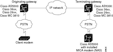
The figure below illustrates the connection from the client modem to a MICA technologies modem network access server (NAS).
How to Configure Modem Passthrough over VoIP
By default, modem passthrough over VoIP capability and redundancy are disabled.

Redundancy can be enabled in one or both of the gateways. When only a single gateway is configured for redundancy, the other gateway receives the packets correctly, but does not produce redundant packets.
See the following sections for the Modem Passthrough over VoIP feature. The two configuration tasks can configure separately or together. If both are configured, the dial-peer configuration takes precedence over the global configuration. Consequently, a call matching a particular dial-peer will first try to apply the modem passthrough configuration on the dial-peer. Then, if a specific dial-peer is not configured, the router will use the global configuration:
- Configuring Modem Passthrough over VoIP Globally
- Configuring Modem Passthrough over VoIP for a Specific Dial Peer
- Troubleshooting Tips
Configuring Modem Passthrough over VoIP Globally
For the Modem Passthrough over VoIP feature to operate, you need to configure modem passthrough in both the originating gateway and the terminating gateway so that the modem call matches a voip dial-peer on the gateway.
When using the voice service voip and modem passthrough nse commands on a terminating gateway to globally set up fax or modem passthrough with NSEs, you must also ensure that each incoming call will be associated with a VoIP dial peer to retrieve the global fax or modem configuration. You associate calls with dial peers by using the incoming called-number command to specify a sequence of digits that incoming calls can match.
To configure the Modem Passthrough over VoIP feature for all the connections of a gateway, use the following commands beginning in global configuration mode:
DETAILED STEPS
Configuring Modem Passthrough over VoIP for a Specific Dial Peer
You can configure the Modem Passthrough over VoIP feature on a specific dial peer in two ways, as follows:
- Globally in the voice-service configuration mode
- Individually in the dial-peer configuration mode on a specific dial peer
The default behavior for the voice-service configuration mode is no modem passthrough. This default behavior implies that modem passthrough is disabled for all dial peers on the gateway by default.
To enable Modem Passthrough on the VoIP dial peers on both the originating and terminating gateway, configure modem passthrough globally or explicitly on the dial peer.
For modem passthrough to operate, you must define VoIP dial peers on both gateways to match the call, for example, by using a destination pattern or an incoming called number. The modem passthrough parameters associated with those dial peers then will apply to the call.
Note | When modem passthrough is configured individually for a specific dial peer, that configuration for the specific dial peer takes precedence over the global configuration. |
To configure the Modem Passthrough over VoIP feature for a specific dial peer, use the following commands beginning in global configuration mode:
DETAILED STEPS
Troubleshooting Tips
To troubleshoot the Modem Passthrough over VoIP feature, perform the following steps:
- Make sure that you can make a voice call.
- Make sure that Modem Passthrough over VoIP is configured on both the originating gateway and the terminating gateway.
- Make sure that both the originating gateway and the terminating gateway have the same named signaling event (NSE) payload-type number.
- Make sure that both the originating gateway and the terminating gateway have the same maximum-sessions value when the two gateways are configured in the voice-service configuration mode.
- Use the debug vtsp dsp and debug vtsp session commands to debug a problem.
Verifying Modem Passthrough over VoIP
1. Enter the show runcommand to verify the configuration.
2. Enter the show dial-peer voice command to verify that Modem Passthrough over VoIP is enabled.
DETAILED STEPS
| Step 1 | Enter the show runcommand to verify the configuration. |
| Step 2 | Enter the show dial-peer voice command to verify that Modem Passthrough over VoIP is enabled. |
Monitoring and Maintaining Modem Passthrough over VoIP
To monitor and maintain the Modem Passthrough over VoIP feature, use the following commands in privileged EXEC mode:
|
Command |
Purpose |
|---|---|
Device# show call active {voice | fax}[brief] |
Displays information for the active call table or displays the voice call history table. The brief option displays a truncated version of either option. |
Device# show dial-peer voice [number | summary] |
Displays configuration information for dial peers. The number argument specifies a specific dial peer from 1 to 32767. The summary option displays a summary of all dial peers. |
Configuration Examples
The following is sample configuration for the Modem Passthrough over VoIP feature:
version 12.1
service timestamps debug uptime
service timestamps log uptime
no service password-encryption
!
voice service voip
	 modem passthrough nse codec g711ulaw redundancy maximum-session 5
!
!
resource-pool disable
!
!
!
!
!
ip subnet-zero
ip ftp source-interface Ethernet0
ip ftp username lab
ip ftp password lab
no ip domain-lookup
!
isdn switch-type primary-5ess
cns event-service server
!
!
!
!
!
mta receive maximum-recipients 0
!
!
controller T1 0
 framing esf
 clock source line primary
 linecode b8zs
 pri-group timeslots 1-24
!
controller T1 1
 shutdown
 clock source line secondary 1
!
controller T1 2
 shutdown
!
controller T1 3
 shutdown
!
!
!
interface Ethernet0
 ip address 1.1.2.2 255.0.0.0
 no ip route-cache
 no ip mroute-cache
!
interface Serial0:23
 no ip address
 encapsulation ppp
 ip mroute-cache
 no logging event link-status
 isdn switch-type primary-5ess
 isdn incoming-voice modem
 no peer default ip address
 no fair-queue
 no cdp enable
 no ppp lcp fast-start
!
interface FastEthernet0
 ip address 26.0.0.1 255.0.0.0
 no ip route-cache
 no ip mroute-cache
 load-interval 30
 duplex full
 speed auto
 no cdp enable
!
ip classless
ip route 17.18.0.0 255.255.0.0 1.1.1.1
no ip http server
!
!
!
!
voice-port 0:D
!
dial-peer voice 1 pots
 incoming called-number 55511..
 destination-pattern 020..
 direct-inward-dial
 port 0:D
 prefix 020
!
dial-peer voice 2 voip
 incoming called-number 020..
 destination-pattern 55511..
 modem passthrough nse codec g711ulaw redundancy
 session target ipv4:26.0.0.2
!
!
line con 0
 exec-timeout 0 0
 transport input none
line aux 0
line vty 0 4
 login
!
!
end
Feature Information for SIP-to-SIP Extended Feature Functionality for Session Border Controllers
The following table provides release information about the feature or features described in this module. This table lists only the software release that introduced support for a given feature in a given software release train. Unless noted otherwise, subsequent releases of that software release train also support that feature.
Use Cisco Feature Navigator to find information about platform support and Cisco software image support. To access Cisco Feature Navigator, go to www.cisco.com/go/cfn. An account on Cisco.com is not required.
| Table 1 | Feature Information for Configuring SIP-to-SIP Extended Feature Functionality for Session Border Controllers |
|
Feature Name |
Releases |
Feature Information |
|---|---|---|
|
SIP-to-SIP Extended Feature Functionality for Session Border Controllers |
12.4(6)T |
The SIP-to-SIP Extended Feature Functionality for Session Border Controllers (SBCs) enables the SIP-to-SIP functionality to conform with RFC 3261 to interoperate with SIP User Agents (UAs). In Cisco IOS Release 12.4(6)S, this feature was implemented on the Cisco Unified Border Element The following commands were introduced or modified: modem passthrough (dial-peer); modem passthrough (voice-service); show call active voice voice; show call history voice voice; show dial-peer voice; voice service. |
|
SIP-to-SIP Extended Feature Functionality for Session Border Controllers |
Cisco IOS XE Release 3.1S Cisco IOS XE Release 3.3S |
The SIP-to-SIP Extended Feature Functionality for Session Border Controllers (SBCs) enables the SIP-to-SIP functionality to conform with RFC 3261 to interoperate with SIP User Agents (UAs). In Cisco IOS Release 12.4(6)S, this feature was implemented on the Cisco Unified Border Element (Enterprise). The following commands were introduced or modified: modem passthrough (dial-peer); modem passthrough (voice-service); show call active voice voice; show call history voice voice; show dial-peer voice; voice service. |
Cisco and the Cisco logo are trademarks or registered trademarks of Cisco and/or its affiliates in the U.S. and other countries. To view a list of Cisco trademarks, go to this URL: www.cisco.com/go/trademarks. Third-party trademarks mentioned are the property of their respective owners. The use of the word partner does not imply a partnership relationship between Cisco and any other company. (1110R)
Any Internet Protocol (IP) addresses and phone numbers used in this document are not intended to be actual addresses and phone numbers. Any examples, command display output, network topology diagrams, and other figures included in the document are shown for illustrative purposes only. Any use of actual IP addresses or phone numbers in illustrative content is unintentional and coincidental.