
 Feedback
Contents
- VPN Access Control Using 802.1X Authentication
- Finding Feature Information
- Prerequisites for VPN Access Control Using 802.1X Authentication
- Restrictions for VPN Access Control Using 802.1X Authentication
- Information About VPN Access Control Using 802.1X Authentication
- How VPN Control Using 802.1X Authentication Works
- 802.1X Authentication Sample Topology and Configuration
- Converged 802.1X Authenticator Support
- 802.1X Supplicant Support
- Converged 802.1X Supplicant Support
- Authentication Using Passwords and MD5
- How to Configure VPN Access Control Using 802.1X Authentication
- Configuring a AAA RADIUS Server
- Configuring a Router
- Enabling 802.1X Authentication
- Configuring Router and RADIUS Communication
- Configuring 802.1X Parameters Retransmissions and Timeouts
- Configuring the Identity Profile
- Configuring the Identity Profile
- Configuring the DHCP Private Pool
- Configuring the DHCP Public Pool
- Configuring the Interface
- Configuring an Interface Without Assigning an Explicit IP Address to the Interface
- Configuring the Necessary Access Control Policies
- Configuring a PC As an 802.1X Supplicant
- Configuring a PC for VPN Access Control Using 802.1X Authentication
- Enabling 802.1X Authentication on a Windows 2000 XP PC
- Enabling 802.1X Authentication on a Windows 2000 PC
- Enabling 802.1X Authentication on a Windows XP PC
- Enabling 802.1X Authentication on Windows 2000 and Windows XP PCs
- Configuring a Router As an 802.1X Supplicant
- Troubleshooting Tips
- Monitoring VPN Access Control Using 802.1X Authentication
- Verifying VPN Access Control Using 802.1X Authentication
- Configuration Examples for VPN Access Control Using 802.1X Authentication
- Typical VPN Access Control Using 802.1X Configuration Example
- Access Control Policies Example
- Additional References
- Feature Information for VPN Access Control Using 802.1X Authentication
VPN Access Control Using 802.1X Authentication
The home access router provides connectivity to the corporate network through a Virtual Private Network (VPN) tunnel through the Internet. In the home LAN, apart from the employee, other members of the household may also be using the same access router. The VPN Access Control Using 802.1X Authentication feature allows enterprise employees to access their enterprise networks from home while allowing other household members to access only the Internet. The feature uses the IEEE 802.1X protocol framework to achieve the VPN access control. The authenticated employee has access to the VPN tunnel and others (unauthenticated users on the same LAN) have access only to the Internet.
An authentication manager has been added to allow more flexible authentication between different authentication methods like, dot1x, MAC address bypass, and web authentication. See the 802.1X Flexible Authentication feature for more information.
- Finding Feature Information
- Prerequisites for VPN Access Control Using 802.1X Authentication
- Restrictions for VPN Access Control Using 802.1X Authentication
- Information About VPN Access Control Using 802.1X Authentication
- How to Configure VPN Access Control Using 802.1X Authentication
- Configuration Examples for VPN Access Control Using 802.1X Authentication
- Additional References
- Feature Information for VPN Access Control Using 802.1X Authentication
Finding Feature Information
Your software release may not support all the features documented in this module. For the latest feature information and caveats, see the release notes for your platform and software release. To find information about the features documented in this module, and to see a list of the releases in which each feature is supported, see the Feature Information Table at the end of this document.
Use Cisco Feature Navigator to find information about platform support and Cisco software image support. To access Cisco Feature Navigator, go to www.cisco.com/go/cfn. An account on Cisco.com is not required.
Prerequisites for VPN Access Control Using 802.1X Authentication
- The PCs connecting behind the router should have 802.1X clients running on them.
- You should know how to configure authentication, authorization, and accounting (AAA) and RADIUS.
- You should be familiar with IP Security (IPSec).
- You should be familiar with Dynamic Host Configuration Protocol (DHCP).
- You should know how to configure user lists on a Cisco access control server (ACS).
Restrictions for VPN Access Control Using 802.1X Authentication
- Easy VPN is not supported.
- VLAN interfaces are currently not supported.
- If there is a switch located between the router and the supplicant (client PC), the Extensible Authentication Protocol over LAN (EAPOL) frames will not reach the router because the switch discards them.
Information About VPN Access Control Using 802.1X Authentication
How VPN Control Using 802.1X Authentication Works
The home access router provides connectivity to the corporate network through a VPN tunnel through the Internet. In the home LAN, both authenticated (employee) and unauthenticated (other household members) users exist, and both have access to the corporate VPN tunnel. Currently there is no existing mechanism to prevent the unauthenticated user from accessing the VPN tunnel.
To distinguish between the users, the VPN Access Control Using 802.1X Authentication feature uses the IEEE 802.1X protocol that allows end hosts to send user credentials on Layer 2 of the network operating system. Unauthenticated traffic users will be allowed to pass through the Internet but will be blocked from accessing the corporate VPN tunnel. The VPN Access Control Using 802.1X feature expands the scope of the 802.1X standard to authenticate devices rather than ports, meaning that multiple devices can be independently authenticated for any given port. This feature separates traffic from authenticated and unauthenticated users so that separate access policies can be applied.
When an 802.1X-capable host starts up, it will initiate the authentication phase by sending the EAPOL-Start 802.1X protocol data unit (PDU) to the reserved IEEE multicast MAC address (01-80-C2-00-00-03) with the Ethernet type or length set to 0x888E.
All 802.1X PDUs will be identified as such by the Ethernet driver and will be enqueued to be handled by an 802.1X process. On some platforms, Ethernet drivers have to program the interface address filter so that EAPOL packets can be accepted.
On the router, the receipt of the EAPOL-Start message will result in the source MAC address being "remembered," and an EAPOL-request or identity PDU being sent to the host. The router will send all host-addressed PDUs to the individual MAC address of the host rather than to the multicast address.
- 802.1X Authentication Sample Topology and Configuration
- Converged 802.1X Authenticator Support
- 802.1X Supplicant Support
- Converged 802.1X Supplicant Support
802.1X Authentication Sample Topology and Configuration
The figure below illustrates a typical scenario in which VPN access control using 802.1X authentication is in place.
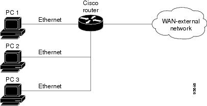
In the figure above, all the PCs are 802.1X capable hosts, and the Cisco router is an authenticator. All the PCs are connected to the built-in hub or to an external hub. If a PC does not support 802.1X authentication, MAC-based authentication is supported on the Cisco router. You can have any kind of connectivity or network beyond the Cisco router WAN.
 Note | If there is a switch located between the router and the supplicant (client PC), the EAPOL frames will not reach the router because the switch discards them. |
Converged 802.1X Authenticator Support
The Cisco IOS commands in Cisco IOS Release 12.4(6)T for 802.1X authenticators have been standardized to work the same way on various Cisco IOS platforms.
802.1X Supplicant Support
There are deployment scenarios in which a network device (a router acting as an 802.1X authenticator) is placed in an unsecured location and cannot be trusted as an authenticator. This scenario requires that a network device be able to authenticate itself against another network device. The 802.1X supplicant support functionality provides the following solutions for this requirement:
- An Extensible Authentication Protocol (EAP) framework has been included so that the supplicant has the ability to "understand" and "respond" to EAP requests. EAP-Message Digest 5 (EAP-MD5) is currently supported.
- Two network devices that are connected through an Ethernet link can act as a supplicant and as an authenticator simultaneously, thus providing mutual authentication capability.
- A network device that is acting as a supplicant can authenticate itself with more than one authenticator (that is, a single port on a supplicant can be connected to multiple authenticators).
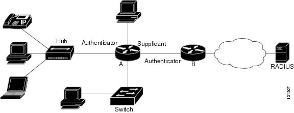
The following illustration is an example of 802.1X supplicant support. The illustration shows that a single supplicant port has been connected to multiple authenticators. Router A is acting as an authenticator to devices that are sitting behind it on the LAN while those devices are acting as supplicants. At the same time, Router B is an authenticator to Router A (which is acting as a supplicant). The RADIUS server is located in the enterprise network.
When Router A tries to authenticate devices on the LAN, it needs to "talk" to the RADIUS server, but before it can allow access to any of the devices that are sitting behind it, it has to prove its identity to Router B. Router B checks the credential of Router A and gives access.
How to Configure VPN Access Control Using 802.1X Authentication
- Configuring a AAA RADIUS Server
- Configuring a Router
- Configuring a PC As an 802.1X Supplicant
- Configuring a Router As an 802.1X Supplicant
- Monitoring VPN Access Control Using 802.1X Authentication
- Verifying VPN Access Control Using 802.1X Authentication
Configuring a AAA RADIUS Server
DETAILED STEPS
Configuring a Router
- Enabling 802.1X Authentication
- Configuring Router and RADIUS Communication
- Configuring 802.1X Parameters Retransmissions and Timeouts
- Configuring the Identity Profile
- Configuring the Identity Profile
- Configuring the DHCP Private Pool
- Configuring the DHCP Public Pool
- Configuring the Interface
- Configuring an Interface Without Assigning an Explicit IP Address to the Interface
- Configuring the Necessary Access Control Policies
Enabling 802.1X Authentication
To enable 802.1X port-based authentication, you should configure the router so that it can communicate with the AAA server, enable 802.1X globally, and enable 802.1X on the interface. To enable 802.1X port-based authentication, perform the following steps.
DETAILED STEPS
| Command or Action | Purpose | |
|---|---|---|
Step 1 |
enable
Example: Router> enable |
Enables privileged EXEC mode.
|
Step 2 |
configure
terminal
Example: Router# configure terminal |
Enters global configuration mode. |
Step 3 |
aaa
new-model
Example: Router (config)# aaa new-model |
Enables AAA. |
Step 4 |
aaa
authentication
dot1x
{default |
listname}
method1 [method2...]
Example: Router (config)# aaa authentication dot1x default group radius |
Creates a series of authentication methods that are used to determine user previlege to access the privileged command level. |
Step 5 |
dot1x
system-auth-control
Example: Router (config)# dot1x system-auth-control |
Globally enables 802.1X port-based authentication. |
Step 6 |
identity
profile
default
Example: Router (config)# identity profile default |
Creates an identity profile and enters dot1x profile configuration mode. |
Step 7 |
interface
type
slot
/
port
Example: Router (config-identity-prof)# interface fastethernet 0/1 |
Enters interface configuration mode and specifies the interface to be enabled for 802.1X port-based authentication. |
Step 8 |
dot1x
port-control
auto
Example: Router (config-if)# dot1x port-control auto |
Enables 802.1X port-based authentication on the interface. |
Examples
The following example shows that 802.1X authentication has been configured on a router:
Router# configure terminal
Router(config)# aaa new-model
Router(config)# aaa authentication dot1x default group radius group radius
Router(config)# dot1x system-auth-control
Router(config)# interface fastethernet 1
Router(config-if)# dot1x port-control auto
The following show dot1x command sample output shows that 802.1X authentication has been configured on a router:
Router# show dot1x all
Sysauthcontrol              Enabled
Dot1x Protocol Version            2
Dot1x Info for FastEthernet1
-----------------------------------
PAE                       = AUTHENTICATOR
PortControl               = AUTO
ControlDirection          = Both
HostMode                  = MULTI_HOST
ReAuthentication          = Enabled
QuietPeriod               = 600
ServerTimeout             = 60
SuppTimeout               = 30
ReAuthPeriod              = 1800 (Locally configured)
ReAuthMax                 = 2
MaxReq                    = 3
TxPeriod                  = 60
RateLimitPeriod           = 60
Configuring Router and RADIUS Communication
DETAILED STEPS
| Command or Action | Purpose | |
|---|---|---|
Step 1 |
enable
Example: Router> enable |
Enables privileged EXEC mode.
|
Step 2 |
configure
terminal
Example: Router# configure terminal |
Enters global configuration mode. |
Step 3 |
ip
radius
source-interface
interface-name
Example: Router (config)# ip radius source-interface fastethernet1 |
Forces RADIUS to use the IP address of a specified interface for all outgoing RADIUS packets. |
Step 4 |
radius-server
host
{hostname |
ip-address}
Example: Router (config)# radius-server host 192.0.2.0 |
Configures the RADIUS server host name or IP address of the router.
|
Step 5 |
radius-server
key
string
Example: Router (config)# radius-server key radiuskey |
Configures the authorization and encryption key used between the router and the RADIUS daemon running on the RADIUS server.
|
Configuring 802.1X Parameters Retransmissions and Timeouts
Various 802.1X retransmission and timeout parameters can be configured. Because all of these parameters have default values, configuring them is optional. To configure the retransmission and timeout parameters, perform the following steps.
DETAILED STEPS
| Command or Action | Purpose | |
|---|---|---|
Step 1 |
enable
Example: Router> enable |
Enables privileged EXEC mode. |
Step 2 |
configure
terminal
Example: Router# configure terminal |
Enters global configuration mode. |
Step 3 |
interface
type
slot
/
port
Example: Router (config)# interface FastEthernet 0/1 |
Enters interface configuration mode and specifies the interface to be enabled for 802.1X port-based authentication. |
Step 4 |
dot1x
max-req
number-of-retries
Example: Router (config-if)# dot1x max-req 3 |
Sets the maximum number of times that the router sends an EAP request/identity frame (assuming that no response is received) to the supplicant before concluding that the supplicant does not support 802.1X. |
Step 5 |
dot1x
port-control
[auto|
force-authorized|
force-unauthorized]
Example: Router (config-if)# dot1x port-control auto |
Sets the port control value.
|
Step 6 |
dot1x
control-direction
{both |
in}
Example: Router (config-if)# dot1x control-direction both |
Changes the port control to unidirectional or bidirectional. |
Step 7 |
dot1x
reauthentication
Example: Router (config-if)# dot1x reauthentication |
Enables periodic reauthentication of the supplicants on the interface. |
Step 8 |
dot1x
timeout
tx-period
seconds
Example: Router (config-if)# dot1x timeout tx-period 60 |
Sets the timeout for supplicant retries. |
Step 9 |
dot1x
timeout
server-timeout
seconds
Example: Router (config-if)# dot1x timeout server-timeout 60 |
Sets the timeout for RADIUS retries. |
Step 10 |
dot1x
timeout
reauth-period
seconds
Example: Router (config-if)# dot1x timeout reauth-period 1800 |
Sets the time after which an automatic reauthentication should be initiated. |
Step 11 |
dot1x
timeout
quiet-period
seconds
Example: Router (config-if)# dot1x timeout quiet-period 600 |
The time after which authentication is restarted after the authentication has failed. |
Step 12 |
dot1x
timeout
ratelimit-period
seconds
Example: Router (config-if)# dot1x timeout ratelimit-period 60 |
The rate limit period throttles the EAP-START packets from misbehaving supplicants. |
Examples
The following configuration example shows that various retransmission and timeout parameters have been configured:
Router# configure terminal
Router(config)# interface FastEthernet1
Router(config-if)# dot1x port-control auto
Router(config-if)# dot1x reauthentication
Router(config-if)# dot1x timeout reauth-period 1800
Router(config-if)# dot1x timeout quiet-period 600
Router(config-if)# dot1x timeout supp-timeout 60
Router(config-if)# dot1x timeout server-timeout 60
Configuring the Identity Profile
The identity profile default command allows you to configure the static MAC addresses of the client that do not support 802.1X and to authorize or unauthorize them statically. The VPN Access Control Using 802.1X Authentication feature allows authenticated and unauthenticated users to be mapped to different interfaces. Under the dot1x profile configuration mode, you can specify the virtual template interface that should be used to create the virtual-access interface to which unauthenticated supplicants will be mapped. To specify which virtual template interface should be used to create the virtual access interface, perform the following steps.
DETAILED STEPS
| Command or Action | Purpose | |
|---|---|---|
Step 1 |
enable
Example: Router> enable |
Enables privileged EXEC mode. |
Step 2 |
configure
terminal
Example: Router# configure terminal |
Enters global configuration mode. |
Step 3 |
identity
profile
default
Example: Router (config)# identity profile default |
Creates an identity profile and enters identity profile configuration mode. |
Step 4 |
description
line-of-description
Example: Router (config-identity-prof)# description description 1 |
Associates descriptive text with the profile. |
Step 5 |
template
virtual-template
Example: Router (config-identity-prof)# template virtual-template 1 |
Specifies the virtual template interface that will serve as the configuration clone source for the virtual interface that is dynamically created for authenticated users. |
Step 6 |
device
[authorize |
not-authorize]
mac-address
mac-address
Example: Router (config-identity-prof)# device authorize mac-address 1.1.1 |
Statically authorizes or unauthorizes a supplicant (by giving its MAC address) if the supplicant does not "understand" 802.1X. |
Step 7 |
device
authorize
type
device-type
Example: Router (config-identity-prof)# device authorize type cisco ip phone |
Statically authorizes or unauthorizes a device type. |
Examples
The following example shows that Cisco IP phones and a specific MAC address have been statically authorized:
Router# configure terminal
Router (config)# identity profile default
Router(config-1x-prof)# description put the description here
Router(config-1x-prof)# template virtual-template1
Router(config-1x-prof)# device authorize type cisco ip phone
Router(config-1x-prof)# device authorize mac-address 0001.024B.B4E7
Configuring the Identity Profile
DETAILED STEPS
| Command or Action | Purpose | |
|---|---|---|
Step 1 |
enable
Example: Router> enable |
Enables privileged EXEC mode.
|
Step 2 |
configure
terminal
Example: Router# configure terminal |
Enters global configuration mode. |
Step 3 |
identity
profile
default
Example: Router (config)# identity profile default |
Creates an identity profile and enters identity profile configuration mode. |
Step 4 |
description
description-string
Example: Router (config-identity-prof)# description description_string_goes_here |
Associates descriptive text with the identity profile. |
Step 5 |
template
virtual-template
Example: Router (config-identity-prof)# template virtualtemplate1 |
Specifies the virtual template interface that will serve as the configuration clone source for the virtual interface that is dynamically created for authenticated users. |
Step 6 |
exit
Example: Router (config-template)# exit |
Exits identity profile configuration mode. |
Configuring the DHCP Private Pool
The VPN Access Control Using 802.1X Authentication feature can be configured with one DHCP pool or two. If there are two pools, the unauthenticated and authenticated devices will get their addresses from separate DHCP pools. For example, the public pool can have an address block that has only local significance, and the private pool can have an address that is routable over the VPN tunnel.
DETAILED STEPS
| Command or Action | Purpose | |
|---|---|---|
Step 1 |
ip
dhcp
pool
name
Example: Router (config)# ip dhcp pool private |
Configures a DHCP private address pool on a Cisco IOS DHCP server and enters DHCP pool configuration mode. |
Step 2 |
network
network-number
[mask]
Example: Router (dhcp-config)# network 209.165.200.225 255.255.255.224 |
Configures the subnet number and mask for a DHCP private address pool on a Cisco IOS DHCP server. |
Step 3 |
default-router
address
Example: Router (dhcp-config)# default-router 192.0.2.2 |
Specifies the default router list for a DHCP client. |
Configuring the DHCP Public Pool
The VPN Access Control Using 802.1X Authentication feature can be configured with one DHCP pool or two. If there are two pools, the unauthenticated and authenticated devices will get their addresses from separate DHCP pools. For example, the public pool can have an address block that has only local significance, and the private pool can have an address that is routable over the VPN tunnel.
DETAILED STEPS
| Command or Action | Purpose | |
|---|---|---|
Step 1 |
ip
dhcp
pool
name
Example: Router (config-dhcp)# ip dhcp pool public |
Configures the DHCP public address pool on a Cisco IOS DHCP server. |
Step 2 |
network
network-number
[mask]
Example: Router (config-dhcp)# network 209.165.200.226 255.255.255.224 |
Configures the subnet number and mask for a DHCP public address pool on a Cisco IOS DHCP server. |
Step 3 |
default-router
address
Example: Router (config-dhcp)# default-router 192.0.2.3 |
Specifies the default router list for a DHCP client. |
Step 4 |
exit
Example: Router (config-dhcp)# exit |
Exits DHCP pool configuration mode. |
Configuring the Interface
DETAILED STEPS
| Command or Action | Purpose | |
|---|---|---|
Step 1 |
configure
terminal
Example: Router# configure terminal |
Enters global configuration mode. |
Step 2 |
interface
type
slot
/
port
Example: Router (config)# interface loopback 0/1 |
Enters interface configuration mode and specifies the interface to be enabled. |
Step 3 |
ip
address
ip-address
mask
[secondary]
Example: Router (config-if)# ip address 209.165.200.227 255.255.255.224 |
Sets the private IP address for the interface. |
Step 4 |
interface
virtual-template
number
Example: Router (config-if)# interface virtual-template 1 |
Creates a virtual template interface that can be configured and applied dynamically in creating virtual access interfaces. |
Step 5 |
ip
address
ip-address
mask
[secondary]
Example: Router (config-if)# ip address 209.165.200.227 255.255.255.224 |
Sets the public IP address for the interface. |
Step 6 |
exit
Example: Router (config-if)# exit |
Exits interface configuration mode. |
Configuring an Interface Without Assigning an Explicit IP Address to the Interface
DETAILED STEPS
| Command or Action | Purpose | |
|---|---|---|
Step 1 |
enable
Example: Router# enable |
Enables privileged EXEC mode.
|
Step 2 |
configure
terminal
Example: Router# configure terminal |
Enters global configuration mode. |
Step 3 |
interface
type
slot
/
port
Example: Router (config)# interface virtual-template 1 |
Enters interface configuration mode and specifies the interface to be enabled. |
Step 4 |
ip
unnumbered
type
number
Example: Router (config-if)# ip unnumbered loopback 0 |
Enables IP processing on an interface without assigning an explicit IP address to the interface. |
Example
The following example shows that the identity profile associates virtual-template1 with unauthenticated supplicants. Virtual-template1 gets its IP address from interface loopback 0, and unauthenticated supplicants are associated with a public pool. Authenticated users are associated with a private pool.
Router(config)# identity profile default
Router(config-identity-prof)# description put the description here
Router(config-identity-prof)# template virtual-template1
Router(config-identity-prof)# exit
Router(config)# ip dhcp pool private
Router(dhcp-config)# default-router 192.0.2.0
Router(dhcp-config)# exit
Router(config)#ip dhcp pool public
Router(dhcp-config)# default-router 192.0.2.1
Router(dhcp-config)# exit
Router(config)# interface
Router(dhcp-config)# network 209.165.200.225 255.255.255.224
Router(dhcp-config)# default-router 192.0.2.1
Router(dhcp-config)# exit
Router(config)# interface loopback0
Router(config-if)# interface ethernet0
Router(config-if)# ip address 209.165.200.226 255.255.255.224
Router(config-if)# exit
Router(config)# interface virtual-template1
Router(config-if)# ip unnumbered loopback 0
Configuring the Necessary Access Control Policies
802.1X authentication separates traffic from authenticated and unauthenticated devices. Traffic from authenticated devices transit through the physical interface, and unauthenticated traffic transits through the Virtual-Template1. Therefore, different policies can be applied on each interface. The configuration will also depend on whether two DHCP pools or a single DHCP pool is being used. If a single DHCP pool is being used, access control can be configured on Virtual-Template1, which will block any traffic from going to the networks to which unauthenticated devices should not have access. These networks (to which unauthenticated devices should not have access) could be the corporate subnetworks protected by the VPN or encapsulated by generic routing encapsulation (GRE). There can also be access control that restricts the access between authenticated and unauthenticated devices.
If two pools are configured, the traffic from a non-trusted pool is routed to the Internet using Network Address Translation (NAT), whereas trusted pool traffic is forwarded through a VPN tunnel. The routing can be achieved by configuring ACLs used by NAT and VPN accordingly.
For an example of an access control policy configuration, see the Access Control Policies Example section.
Configuring a PC As an 802.1X Supplicant
- Configuring a PC for VPN Access Control Using 802.1X Authentication
- Enabling 802.1X Authentication on a Windows 2000 XP PC
- Enabling 802.1X Authentication on a Windows 2000 PC
- Enabling 802.1X Authentication on a Windows XP PC
- Enabling 802.1X Authentication on Windows 2000 and Windows XP PCs
Configuring a PC for VPN Access Control Using 802.1X Authentication
To configure your PC for VPN Access Control Using 802.1X Authentication, perform the following steps.
1. Enable 802.1X for MD5.
2. Enable DHCP.
DETAILED STEPS
| Step 1 | Enable 802.1X for MD5. |
| Step 2 | Enable DHCP. |
Enabling 802.1X Authentication on a Windows 2000 XP PC
802.1X implementation on a Windows 2000/XP PC is unstable. A more stable 802.1X client, AEGIS (beta) for Microsoft Windows, is available at the Meetinghouse Data Communications website at www.mtghouse.com.
Enabling 802.1X Authentication on a Windows 2000 PC
DETAILED STEPS
| Step 1 |
Make sure that the PC has at least Service Pack 3.
Go to the page "Microsoft 802.1x Authentication Client" on the Microsoft Windows 2000 website at the following URL: http://www.microsoft.com/windows2000/server/evaluation/news/bulletins/8021xclient.asp. At the above site, download and install 802.1X client for Windows 2000. If the above site is unavailable, search for the "Q313664: Recommended Update" page on the Microsoft Windows 2000 website at the following URL: http://www.microsoft.com/windows2000/downloads/recommended/q313664/default.asp |
| Step 2 | Reboot your PC after installing the client. |
| Step 3 |
Go to the Microsoft Windows registry and add or install the following entry:
"HKLM\Software\Microsoft\EAPOL\Parameters\General\Global\SupplicantMode REG_DWORD 3" ("SupplicantMode" key entry is not there by default under Global option in the registry. So add a new entry named "SupplicantMode" as REG_DOWORD and then set its value to 3.) |
| Step 4 | Reboot your PC. |
Enabling 802.1X Authentication on a Windows XP PC
DETAILED STEPS
| Step 1 |
Go to the Microsoft Windows registry and install the following entry there:
"HKLM\Software\Microsoft\EAPOL\Parameters\General\Global\SupplicantMode REG_DWORD 3" |
| Step 2 | Reboot your PC. |
Enabling 802.1X Authentication on Windows 2000 and Windows XP PCs
To enable 802.1X authentication on Windows 2000 and Windows XP PCs, that is, if you are operating both at the same time, perform the following steps.
DETAILED STEPS
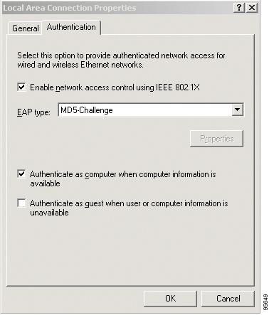
| Step 1 | Open the Network and Dial-up Connections window on your computer. |
| Step 2 |
Right-click the Ethernet interface (Local Area Connection) to open the properties window. It should have a tab called "Authentication."
Click the Authentication tab. Select the check box titled "Enable network access control using IEEE 802.1X." In a short period of time you should see a dialog box (for Windows 2000) or a floating window asking you to select it. Select it, and when the next window appears, enter the username and password in this dialog box. See the figure below. |
What to Do Next
Configuring a Router As an 802.1X Supplicant
DETAILED STEPS
| Command or Action | Purpose | |
|---|---|---|
Step 1 |
enable
Example: Router> enable |
Enables privileged EXEC mode. |
Step 2 |
configure
terminal
Example: Router# configure terminal |
Enters global configuration mode. |
Step 3 |
aaa
authentication
dot1x
{default |
listname}
method1 [method2...]
Example: Router(config)# aaa authentication dot1x default group radius |
Specifies one or more authentication, authorization, and accounting (AAA) methods for use on interfaces running IEEE 802.1X. |
Step 4 |
dot1x
credentials
name
Example: Router(config)# dot1x credentials name1 |
Specifies the 802.1X credential profile to use when configuring a supplicant. |
Step 5 |
username
name
Example: Router(config-dot1x-creden)# username username1 |
Specifies the username for an 802.1X credentials profile. |
Step 6 |
password
[0 |
7]
password
Example: Router(config-dot1x-creden)# password 0 password1 |
Specifies the password for an 802.1X credentials profile. |
Step 7 |
exit
Example: Router(config-dot1x-creden)# exit |
Enters global configuration mode. |
Step 8 |
interface
type
number
Example: Router(config)# interface Fastethernet0/0 |
Enters interface configuration mode. |
Step 9 |
dot1x
pae
supplicant
Example: Router(config-if)# dot1x pae supplicant |
Sets the Port Access Entity (PAE) type as supplicant. |
Step 10 |
dot1x
credentials
name
Example: Router(config-if)# dot1x credentials name1 |
Specifies the 802.1X credential profile to use when configuring a supplicant. |
Step 11 |
end
Example: Router(config-if)# end |
(Optional) Exits the current configuration mode. |
Monitoring VPN Access Control Using 802.1X Authentication
To monitor VPN Access Control Using 802.1X Authentication, perform the following steps. The commands shown in the steps may be used one at a time and in no particular order.
DETAILED STEPS
| Command or Action | Purpose | |
|---|---|---|
Step 1 |
enable
Example: Router> enable |
Enables privileged EXEC mode.
|
Step 2 |
clear
dot1x
{all |
interface}
Example: Router# clear dot1x all |
Clears 802.1X interface information. |
Step 3 |
clear
eap
sessions
[credentials
credentials-name |
interface
interface-name |
method
method-name |
transporttransport-name]]
Example: Router# clear eap sessions credentials type1 |
Clears EAP information on a switch or for a specified port. |
Step 4 |
debug
dot1x
[
all
|
errors
|
events
|
feature
|
packets
|
redundancy
|
registry
|
state-machine
]
Example: Router# debug dot1x all |
Displays 802.1X debugging information.
|
Step 5 |
debug
eap
[all |
method] [authenticator |
peer] {all |
errors |
events |
packets |
sm}
Example: Router# debug eap all |
Displays information about EAP. |
Step 6 |
dot1x
initialize
[interface
interface-name]
Example: Router# dot1x initialize interface FastEthernet1 |
Initializes an interface. |
Step 7 |
dot1x
re-authenticate
interface-type
interface-number
Example: Router# dot1x re-authenticate FastEthernet1 |
Reauthenticates all the authenticated devices that are attached to the specified interface. |
Verifying VPN Access Control Using 802.1X Authentication
DETAILED STEPS
| Command or Action | Purpose | |
|---|---|---|
Step 1 |
enable
Example: Router> enable |
Enables privileged EXEC mode.
|
Step 2 |
show
dot1x
[interface
interface-name[details]]
Example: Router# show dot1x interface FastEthernet 1 details |
Shows details for an identity profile. |
Step 3 |
show
eap
registrations
[method |
transport]
Example: Router# show eap registrations method |
Displays EAP registration information. |
Step 4 |
show
eap
sessions
[credentials
credentials-name |
interfaceinterface-name |
method
method-name |
transport
transport-name]
Example: Router# show eap sessions interface gigabitethernet1/0/1 |
Displays active EAP session information. |
Configuration Examples for VPN Access Control Using 802.1X Authentication
Typical VPN Access Control Using 802.1X Configuration Example
The following sample output shows that VPN access control using 802.1X authentication has been configured. Output is shown for the router and for the gateway.
Router
Router# show running-config
Building configuration...
Current configuration : 2457 bytes
!
version 12.4
no service pad
service timestamps debug datetime msec
service timestamps log datetime msec
no service password-encryption
!
hostname 871-1
!
boot-start-marker
boot-end-marker
!
logging message-counter syslog
!
aaa new-model
!
!
aaa authentication dot1x default group radius group radius
!
!
aaa session-id common
!
!
dot11 syslog
ip source-route
!
ip dhcp pool private
   network 209.165.200.225 255.255.255.224
   default-router 192.0.2.18
!
ip dhcp pool public
   network 209.165.200.226 255.255.255.224
   default-router 192.0.2.17
!
ip dhcp pool name
   default-router 192.0.2.16
!
!
ip cef
no ip domain lookup
ip host sjc-tftp02 192.0.2.15
ip host sjc-tftp01 192.0.2.14
ip host dirt 192.0.2.13
!
!
!
template virtualtemplate1
!
dot1x system-auth-control
dot1x credentials basic-user
 description This credentials profile should be used for most configured ports
 username router1
 password 0 secret
!
identity profile default
 description description 1
 device authorize mac-address 0001.024b.b4e7
 device authorize mac-address 0001.0001.0001
 device authorize type cisco ip phone
 template Virtual-Template1
!
!
!
!
!
archive
 log config
  hidekeys
!
!
!
!
!
interface Loopback0
 ip address 209.165.200.227 255.255.255.224
!
interface FastEthernet0
!
interface FastEthernet1
 dot1x pae authenticator
 dot1x port-control auto
 dot1x timeout quiet-period 600
 dot1x timeout server-timeout 60
 dot1x timeout reauth-period 1800
 dot1x timeout tx-period 60
 dot1x timeout ratelimit-period 60
 dot1x max-req 3
 dot1x reauthentication
!
interface FastEthernet2
!
interface FastEthernet3
!
interface FastEthernet4
 no ip address
 shutdown
 duplex auto
 speed auto
!
interface Virtual-Template1
 ip unnumbered Loopback0
!
interface Dot11Radio0
 no ip address
 shutdown
 speed basic-1.0 basic-2.0 basic-5.5 6.0 9.0 basic-11.0 12.0 18.0 24.0 36.0 48.0
 station-role root
 no cdp enable
!
interface Vlan1
 ip address 209.165.200.228 255.255.255.224
!
ip default-gateway 192.0.2.10
ip default-network 192.0.2.11
ip forward-protocol nd
ip route 0.0.0.0 0.0.0.0 192.0.2.11
ip route 209.165.200.229 255.255.255.224 192.0.2.12
no ip http server
no ip http secure-server
!
!
ip radius source-interface FastEthernet1
!
!
!
radius-server host 192.0.2.9 auth-port 1645 acct-port 1646
radius-server key radiuskey
!
control-plane
!
!
line con 0
 exec-timeout 30 0
 logging synchronous
 no modem enable
line aux 0
line vty 0 4
 privilege level 15
 password lab
!
scheduler max-task-time 5000
end
Peer Router As Gateway
Router# show running-config
Building configuration...
Current configuration: 1828 bytes
!
version 12.3
service timestamps debug datetime msec
service timestamps log datetime msec
no service password-encryption
!
hostname c3725
!
!
no aaa new-model
ip subnet-zero
!
vpdn enable
!
vpdn-group 1
 accept-dialin
  protocol pppoe
  virtual-template 1
!
mpls ldp logging neighbor-changes
!
crypto isakmp policy 1
 authentication pre-share
crypto isakmp key 0 test address 192.0.2.8
!
!
crypto ipsec transform-set t1 ah-md5-hmac esp-des
crypto mib ipsec flowmib history tunnel size 2
crypto mib ipsec flowmib history failure size 2
!
crypto map test 1 ipsec-isakmp
 set peer 192.0.2.7
 set transform-set t1
 match address 101
!
no voice hpi capture buffer
no voice hpi capture destination
!
interface Loopback0
 description corporate
 ip address 209.165.200.230 255.255.255.224
!
interface Loopback1
 description internet
 ip address 209.165.200.231 255.255.255.224
!
interface FastEthernet0/0
 ip address 209.165.200.232 255.255.255.224
 duplex auto
 speed auto
!
interface FastEthernet0/1
 no ip address
 speed auto
 half-duplex
 pppoe enable
!
interface ATM1/0
 ip address 209.165.200.233 255.255.255.224
 no atm ilmi-keepalive
 pvc 1/43
  protocol ip 192.0.2.6 broadcast
  encapsulation aal5snap
!
!
interface FastEthernet2/0
 no ip address
 speed auto
 full-duplex
!
interface FastEthernet2/1
 no ip address
 shutdown
 duplex auto
 speed auto
!
interface Virtual-Template1
 ip address 209.165.200.234 255.255.255.224
 ip mtu 1492
 crypto map test
!
!
router rip
 network 192.0.2.5
 network 192.0.2.4
 network 192.0.2.3
 network 192.0.2.2
 network 192.0.2.1
!
ip http server
no ip http secure-server
ip classless
!
access-list 101 permit ip 10.5.0.0 0.0.0.255 10.0.0.1 0.0.0.255
no cdp log mismatch duplex
!
line con 0
 exec-timeout 0 0
line aux 0
line vty 0 4
 login
!
!
end
Access Control Policies Example
Single DHCP pool
ip dhcp pool private
 network 209.165.200.236 255.255.255.224
 default-router 20.0.0.1
 exit
crypto isakmp policy 1
 authentication pre-share
!
crypto isakmp key test address address
 crypto ipsec transform-set t1 esp-3des esp-sha-hmac
 mode tunnel
 crypto map test 1 ipsec-isakmp
 set peer address
 set transform-set t1
 match address 101
 access-list 101 permit ip 10.0.0.0 0.0.0.255 50.0.0.0 0.0.0.255
 access-list 102 deny ip 10.0.0.0 0.0.0.255 50.0.0.0 0.0.0.255
 access-list 102 permit  ip any any
!
interface Ethernet0
! inside interface
! dot1x configs
!
interface Virtual-Template1
! Deny traffic from going to VPN
 ip access-group 102 in
!
Interface Ethernet1
! outside interface
 crypto map test
Two DHCP Pools
ip dhcp pool private
 network 209.165.200.237 255.255.255.224
 default-router 192.0.2.1
 exit
!
ip dhcp pool public
 network 209.165.200.238 255.255.255.224
 default-router 192.0.2.0
 exit
!
crypto isakmp policy 1
 authentication pre-share
!
crypto isakmp key test address address
 crypto ipsec transform-set t1 esp-3des esp-sha-hmac
 mode tunnel
 crypto map test 1 ipsec-isakmp
 set peer address
 set transform-set t1
 match address 101
 access-list 101 permit ip 10.0.0.0 0.0.0.255 10.10.0.0 0.0.0.255
 access-list 102 permit ip 10.0.0.1 0.0.0.255 any
!
interface Ethernet0
!inside interface
! dot1x configs
!
interface Loopback0
 ip address 209.165.200.239 255.255.255.224
!
interface Virtual-Template1
 ip unnumbered Loopback0
 ip nat inside
!
Interface Ethernet1
! outside interface
 crypto map test
 ip nat outside
!
ip nat inside source list 102 interface Ethernet1 overload
Additional References
Related Documents
|
Related Topic |
Document Title |
|---|---|
|
Configuring 802.1X port-based authentication |
Configuring IEEE 802.1X Port-Based Authentication module. |
|
DHCP |
Cisco IOS IP Addressing Services Configuration Guide |
|
IPSec |
Cisco IOS Security Configuration Guide: Secure Connectivity, Release 15.0. |
|
RADIUS |
Configuring RADIUS module. |
|
Security commands |
Cisco IOS Security Command Reference |
|
User lists on a Cisco ACS |
User Guide for Cisco Secure ACS for Windows Server Version 3.2. |
MIBs
Technical Assistance
|
Description |
Link |
|---|---|
|
The Cisco Support and Documentation website provides online resources to download documentation, software, and tools. Use these resources to install and configure the software and to troubleshoot and resolve technical issues with Cisco products and technologies. Access to most tools on the Cisco Support and Documentation website requires a Cisco.com user ID and password. |
Feature Information for VPN Access Control Using 802.1X Authentication
The following table provides release information about the feature or features described in this module. This table lists only the software release that introduced support for a given feature in a given software release train. Unless noted otherwise, subsequent releases of that software release train also support that feature.
Use Cisco Feature Navigator to find information about platform support and Cisco software image support. To access Cisco Feature Navigator, go to www.cisco.com/go/cfn. An account on Cisco.com is not required.
| Table 1 | Feature Information for VPN Access Control Using 802.1X Authentication |
|
Feature Name |
Releases |
Feature Information |
|---|---|---|
|
VPN Access Control Using 802.1X Authentication |
12.3(2)XA |
The VPN Access Control Using 802.1X Authentication feature was introduced. This feature allows enterprise employees to access their enterprise networks from home while allowing other household members to access only the Internet. |
|
VPN Access Control Using 802.1X Authentication |
12.3(4)T |
This feature was integrated into Cisco IOS Release 12.3(4)T, and the following platform support was added: Cisco 1751, Cisco 2610XM - Cisco 2611XM, Cisco 2620XM - Cisco 2621XM, Cisco 2650XM - Cisco 2651XM, Cisco 2691, Cisco 3640, Cisco 3640A, and Cisco 3660. |
|
802.1X Supplicant Support |
12.3(11)T |
802.1X supplicant support was added. |
|
Converged 802.1X Authenticator and Converged 802.1X Supplicant Support |
12.4(6)T |
Converged 802.1X authenticator and converged 802.1X supplicant support was added. (This update is a standardization of Cisco IOS 802.1X commands for various Cisco IOS platforms. This is no change in 802.1X features.) Affected commands include the following: clear eap , debug dot1x , debug eap , description (dot1x credentials) , dot1x control-direction , dot1x credentials , dot1x default , dot1x host-mode , dot1x max-reauth-req , dot1x max-start , dot1x multiple-hosts , dot1x timeout , eap , identity profile , password (dot1x credentials) , show eap registrations , show eap sessions, and username |
|
VPN Access Control Using 802.1X Authentication |
12.4(4)XC |
Various 802.1X commands were integrated into Cisco IOS Release 12.4(4)XC for Cisco 870 Integrated Services Routers (ISRs) only. Affected commands include the following: dot1x control-direction , dot1x default , dot1x guest-vlan , dot1x host-mode , dot1x max-reauth-req , dot1x max-req , dot1x max-start , dot1x pae , dot1x port-control , dot1x re-authenticate (privileged EXEC) , dot1x reauthentication , dot1x system-auth-control , dot1x timeout, macro global , macro name, and show ip igmp snooping |
Cisco and the Cisco logo are trademarks or registered trademarks of Cisco and/or its affiliates in the U.S. and other countries. To view a list of Cisco trademarks, go to this URL: www.cisco.com/go/trademarks. Third-party trademarks mentioned are the property of their respective owners. The use of the word partner does not imply a partnership relationship between Cisco and any other company. (1110R)
Any Internet Protocol (IP) addresses and phone numbers used in this document are not intended to be actual addresses and phone numbers. Any examples, command display output, network topology diagrams, and other figures included in the document are shown for illustrative purposes only. Any use of actual IP addresses or phone numbers in illustrative content is unintentional and coincidental.