
 Feedback
Contents
- Zone-Based Policy Firewall High Availability
- Finding Feature Information
- Prerequisites for Zone-Based Policy Firewall High Availability
- Restrictions for Zone-Based Policy Firewall High Availability
- Information About Zone-Based Policy Firewall High Availability
- Zone-Based Policy Firewall High Availability Overview
- Zone-Based Policy Firewall High Availability Operation
- Active/Active Failover
- Active/Standby Failover
- Asymmetric Routing Overview
- WAN-LAN Topology
- LAN-LAN Topology
- Exclusive Virtual IP Addresses and Exclusive Virtual MAC Addresses
- Virtual Fragmentation Reassembly
- How to Configure Zone-Based Policy Firewall High Availability
- Configuring Application Redundancy and Redundancy Application Groups
- Configuring a Firewall for High Availability
- Configuring a Redundancy Application Group on a WAN Interface
- Configuring a Redundancy Application Group on a LAN Interface
- Configuration Examples for Zone-Based Policy Firewall High Availability
- Example: Configuring Application Redundancy and Redundancy Application Groups
- Example: Configuring a Firewall for High Availability
- Example: Configuring a Redundancy Application Group on a WAN Interface
- Example: Configuring a Redundancy Application Group on a LAN Interface
- Feature Information for Zone-Based Policy Firewall High Availability
Zone-Based Policy Firewall High Availability
The Zone-Based Policy Firewall High Availability feature enables you to configure pairs of devices to act as backup for each other. High availability (HA) can be configured to determine the active device based on a number of failover conditions. When a failover occurs, the standby device seamlessly takes over and starts forwarding traffic and maintaining a dynamic routing table. The Zone-Based Policy Firewall High Availability feature supports active/active HA, active/standby HA, and asymmetric routing.
- Finding Feature Information
- Prerequisites for Zone-Based Policy Firewall High Availability
- Restrictions for Zone-Based Policy Firewall High Availability
- Information About Zone-Based Policy Firewall High Availability
- How to Configure Zone-Based Policy Firewall High Availability
- Configuration Examples for Zone-Based Policy Firewall High Availability
- Feature Information for Zone-Based Policy Firewall High Availability
Finding Feature Information
Your software release may not support all the features documented in this module. For the latest caveats and feature information, see Bug Search Tool and the release notes for your platform and software release. To find information about the features documented in this module, and to see a list of the releases in which each feature is supported, see the feature information table at the end of this module.
Use Cisco Feature Navigator to find information about platform support and Cisco software image support. To access Cisco Feature Navigator, go to www.cisco.com/go/cfn. An account on Cisco.com is not required.
Prerequisites for Zone-Based Policy Firewall High Availability
- Interfaces attached to a firewall must have the same redundant interface identifier (RII).
-
The active and standby devices must have the same zone-based policy firewall configuration.
-
The active and standby devices must run on an identical version of the Cisco software. The active and standby devices must be connected through a switch.
- For asymmetric routing traffic to pass, you must configure the pass action for the class-default class.
- If you configure a zone pair between two LAN interfaces, ensure that you configure the same redundancy group (RG) on both interfaces. The zone pair configuration is not supported if LAN interfaces belong to different RGs.
Restrictions for Zone-Based Policy Firewall High Availability
- The Zone-Based Policy Firewall High Availability feature is supported only on Integrated Services Routers (ISR) Generation 2 (G2).
- Asymmetric routing is not supported on interfaces that are a part of a redundancy group (RG).
- Asymmetric routing should not be used for load sharing of WAN links because very high asymmetric routing traffic can cause performance degradation of devices.
- A Layer 2 interface that is converted to a Layer 3 interface by using the no switchport command should not be used as a redundancy control link or a data link.
- In an active/active redundancy scenario, there should not be any traffic flow between the interfaces that are part of different RGs. For traffic flow between interfaces, both the interfaces should be part of the same zone or of a different zone with pass action configured between the zones.
- Multiprotocol Label Switching (MPLS) is not supported on asymmetric routing.
- Layer 7 inspection is not HA-aware. If Layer 7 inspection is enabled and the active RG goes down, only Layer 4 sessions will be synchronized to the standby RG; Layer 7 sessions have to be reestablished with the server.
- Zone-based policy firewall supports only Layer 4 protocol inspection with redundancy.
Information About Zone-Based Policy Firewall High Availability
- Zone-Based Policy Firewall High Availability Overview
- Zone-Based Policy Firewall High Availability Operation
- Active/Active Failover
- Active/Standby Failover
- Asymmetric Routing Overview
- WAN-LAN Topology
- LAN-LAN Topology
- Exclusive Virtual IP Addresses and Exclusive Virtual MAC Addresses
- Virtual Fragmentation Reassembly
Zone-Based Policy Firewall High Availability Overview
High availability (HA) enables network-wide protection by providing fast recovery from faults that may occur in any part of a network. HA enables rapid recovery from disruptions to users and network applications.
The zone-based policy firewall supports active/active and active/standby HA failover and asymmetric routing.
The active/active failover allows both devices involved in the failover to forward traffic simultaneously.
When active/standby HA failover is configured, only one of the devices involved in the failover handles the traffic at one time, while the other device is in a standby mode, periodically synchronizing session information from the active device.
Asymmetric routing supports the forwarding of packets from a standby redundancy group to an active redundancy group for packet handling. If this feature is not enabled, the return TCP packets forwarded to the device that did not receive the initial synchronization (SYN) message are dropped because they do not belong to any known existing session.
Zone-Based Policy Firewall High Availability Operation
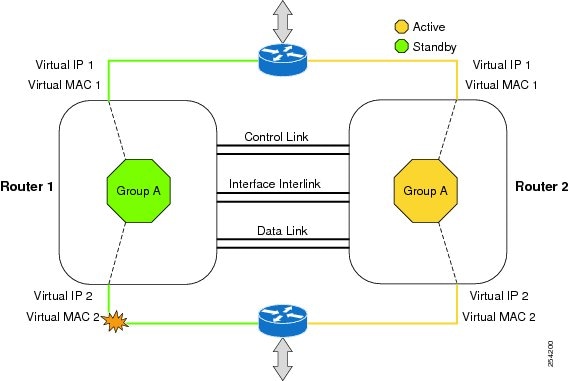
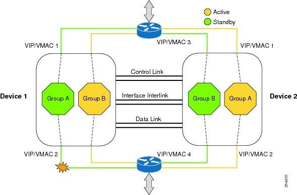
You can configure pairs of devices to act as hot standbys for each other. Redundancy is configured on an interface basis. Pairs of redundant interfaces are known as redundancy groups (RGs). Figure 1 depicts an active/standby load sharing scenario. It shows how a redundancy group is configured for a pair of devices that has one outgoing interface. Figure 2 depicts an active/active load sharing scenario. It shows how two redundancy groups are configured for a pair of devices that have two outgoing interfaces.
In both cases, the redundant devices are joined by a configurable control link, a data synchronization link, and an interlink interface. The control link is used to communicate the status of the devices. The data synchronization link is used to transfer stateful information from the firewall and to synchronize the stateful database. The pairs of redundant interfaces are configured with the same unique ID number, known as the redundant interface identifier (RII).
Asymmetric routing is supported as part of the firewall HA. In a LAN-WAN scenario, where the return traffic enters standby devices, asymmetric routing is supported. To implement the asymmetric routing functionality, configure both the redundant devices with a dedicated interface (interlink interface) for asymmetric traffic. This dedicated interface will redirect the traffic coming to the standby WAN interface to the active device.
The hello time defaults to 3 seconds to align with the Hot Standby Router Protocol (HSRP), and the hold time defaults to 10 seconds. You can also configure these timers in milliseconds by using the timers hellotime msec command.
To determine which pairs of interfaces are affected by the switchover, you must configure a unique ID for each pair of redundant interfaces. This ID is known as the RII that is associated with the interface.
A switchover to the standby device can occur under other circumstances. Another factor that can cause a switchover is a priority setting that can be configured on each device. The device with the highest priority value will be the active device. If a fault occurs on either the active or the standby device, the priority of the device is decremented by a configurable amount, known as the weight. If the priority of the active device falls below the priority of the standby device, a switchover occurs and the standby device becomes the active device. This default behavior can be overridden by disabling the preemption attribute for the redundancy group. You can also configure each interface to decrease the priority when the Layer 1 state of the interface goes down. The priority that is configured overrides the default priority of a redundancy group.
Each failure event that causes a modification of a redundancy group's priority generates a syslog entry that contains a time stamp, the redundancy group that was affected, the previous priority, the new priority, and a description of the failure event cause.
Another situation that can cause a switchover to occur is when the priority of a device or interface falls below a configurable threshold level.
- Power loss or a reload occurs on the active device (this includes crashes).
- The run-time priority of the active device goes down below that of the standby device.
- The run-time priority of the active device goes down below the configured threshold device.
- The redundancy group on the active device is reloaded manually by using the redundancy application reload group rg-number command.
- Two consecutive hello messages missed on any monitored interface forces the interface into testing mode. Both devices will verify the link status on the interface and then execute the following tests:
Active/Active Failover
In an active/active failover configuration, both devices can process network traffic. Active/active failover generates virtual MAC (VMAC) addresses for interfaces in each redundancy group (RG).
- The device that provides the running configuration to the failover pair when they start simultaneously.
- The device on which the failover RG appears in the active state when devices start simultaneously. Each failover RG in the configuration is configured with a primary or secondary device preference. You can configure both failover RGs to be in the active state on a single device and the standby failover RGs to be on the other device. You can also configure one failover RG to be in the active state and the other RG to be in the standby state on a single device.
Active/Standby Failover
Active/standby failover enables you to use a standby device to take over the functionality of a failed device. A failed active device changes to the standby state, and the standby device changes to the active state. The device that is now in the active state takes over IP addresses and MAC addresses of the failed device and starts processing traffic. The device that is now in the standby state takes over standby IP addresses and MAC addresses. Because network devices do not see any change in the MAC-to-IP address pairing, Address Resolution Protocol (ARP) entries do not change or time out anywhere on the network.
In an active/standby scenario, the main difference between two devices in a failover pair depends on which device is active and which device is a standby, namely which IP addresses to use and which device actively passes the traffic. The active device always becomes the active device if both devices start up at the same time (and are of equal operational health). MAC addresses of the active device are always paired with active IP addresses.
Asymmetric Routing Overview
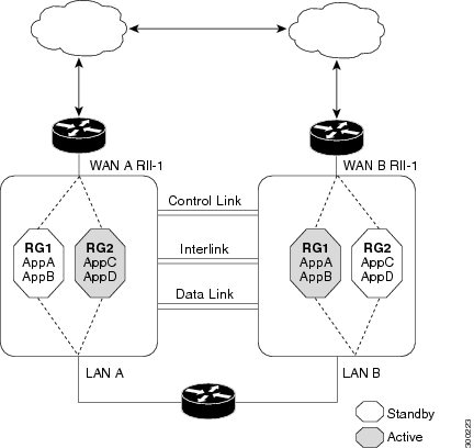
Asymmetric routing occurs when packets from TCP or UDP connections flow in different directions through different routes. In asymmetric routing, packets that belong to a single TCP or UDP connection are forwarded through one interface in a redundancy group (RG), but returned through another interface in the same RG. In asymmetric routing, the packet flow remains in the same RG. When you configure asymmetric routing, packets received on the standby RG are redirected to the active RG for processing. If asymmetric routing is not configured, the packets received on the standby RG may be dropped.
Asymmetric routing determines the RG for a particular traffic flow. The state of the RG is critical in determining the handling of packets. If an RG is active, normal packet processing is performed. In case the RG is in a standby state and you have configured asymmetric routing and the asymmetric-routing always-divert enable command, packets are diverted to the active RG. Use the asymmetric-routing always-divert enable command to always divert packets received from the standby RG to the active RG.
The figure below shows an asymmetric routing scenario with a separate asymmetric-routing interlink interface to divert packets to the active RG.
The following rules apply to asymmetric routing:
- 1:1 mapping exists between the redundancy interface identifier (RII) and the interface.
- 1:n mapping exists between the interface and an RG. (An interface can have multiple RGs.)
- 1:n mapping exists between an RG and applications that use it. (Multiple applications can use the same RG).
- 1:1 mapping exists between an RG and the traffic flow. The traffic flow must map only to a single RG. If a traffic flow maps to multiple RGs, an error occurs.
- RG = 0 for intrabox redundancy.
- 1:1 or 1:n mapping can exist between an RG and an asymmetric-routing interlink as long as the interlink has sufficient bandwidth to support all the RG interlink traffic.
Asymmetric routing consists of an interlink interface that handles all traffic that is to be diverted. The bandwidth of the asymmetric-routing interlink interface must be large enough to handle all expected traffic that is to be diverted. An IPv4 address must be configured on the asymmetric-routing interlink interface, and the IP address of the asymmetric routing interface must be reachable from this interface.

WAN-LAN Topology
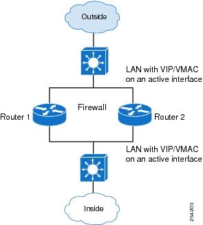
In a WAN-LAN topology, two devices are connected through LAN interfaces on the inside and WAN interfaces on the outside. There is no control on the routing of return traffic received through WAN links.
WAN links can be provided by the same service provider or different service providers. In most cases, WAN links are provided by different service providers. To utilize WAN links to the maximum, configure an external device to provide a failover.
LAN-LAN Topology
Exclusive Virtual IP Addresses and Exclusive Virtual MAC Addresses
Virtual IP (VIP) addresses and virtual MAC (VMAC) addresses are used by security applications to control interfaces that receive traffic. An interface is paired with another interface, and these interfaces are associated with the same redundancy group (RG). The interface that is associated with an active RG exclusively owns the VIP and VMAC. The Address Resolution Protocol (ARP) process on the active device sends ARP replies for any ARP request for the VIP, and the Ethernet controller for the interface is programmed to receive packets destined for the VMAC. When an RG failover occurs, the ownership of the VIP and VMAC changes. The interface that is associated with the newly active RG sends a gratuitous ARP and programs the interface's Ethernet controller to accept packets destined for the VMAC.
IPv6 Support
You can assign each redundancy group (RG) on a traffic interface for both IPv4 and IPv6 virtual IP (VIP) addresses under the same redundancy interface identifier (RII). Each RG uses a unique virtual MAC (VMAC) address per RII. For an RG, the IPv6 link-local VIP and global VIP coexist on an interface.
You can configure an IPv4 VIP, a link-local IPv6 VIP, and/or a global IPv6 VIP for each RG on a traffic interface. IPv6 link-local VIP is mainly used when configuring static or default routes, whereas IPv6 global VIP is widely used in both LAN and WAN topologies.
You must configure a physical IP address before configuring an IPv4 VIP.
Virtual Fragmentation Reassembly
Virtual fragmentation reassembly (VFR) enables the firewall to create dynamic access control lists (ACLs) to protect the network from various fragmentation attacks. VFR is HA-aware. When the firewall is enabled for HA, fragmented packets that arrive on the standby redundancy group (RG) are redirected to the active redundancy group. Use the ip virtual-reassembly command to enable VFR on an interface.
How to Configure Zone-Based Policy Firewall High Availability
- Configuring Application Redundancy and Redundancy Application Groups
- Configuring a Firewall for High Availability
- Configuring a Redundancy Application Group on a WAN Interface
- Configuring a Redundancy Application Group on a LAN Interface
Configuring Application Redundancy and Redundancy Application Groups
DETAILED STEPS
Configuring a Firewall for High Availability
DETAILED STEPS
Configuring a Redundancy Application Group on a WAN Interface
DETAILED STEPS
Configuring a Redundancy Application Group on a LAN Interface
DETAILED STEPS
Configuration Examples for Zone-Based Policy Firewall High Availability
- Example: Configuring Application Redundancy and Redundancy Application Groups
- Example: Configuring a Firewall for High Availability
- Example: Configuring a Redundancy Application Group on a WAN Interface
- Example: Configuring a Redundancy Application Group on a LAN Interface
Example: Configuring a Firewall for High Availability
configure terminal
 class-map type inspect match-any cmap-l4-Protocol
  match protocol tcp
!
 parameter-map type inspect global
  redundancy
!
 policy-map type inspect pmap-l4-Protocols
  class type inspect cmap-l4-Protocol
   inspect
!
  class class-default
			drop
!
!
 zone security TWAN
!
 zone security DATA
!
 zone-pair security zp-TWAN-DATA source TWAN destination DATA
  service-policy type inspect pmap-l4-Protocols
!
 zone-pair security zp-DATA-TWAN source DATA destination TWAN
  service-policy type inspect pmap-l4-Protocols
!
 interface gigabitethernet 0/0/0
  ip address 10.1.1.1 255.255.255.0
  encapsulation dot1q 2
  zone member security private
Example: Configuring a Redundancy Application Group on a WAN Interface
The following example shows how to configure redundancy groups for a WAN-LAN scenario:
interface gigabitethernet 0/0/2
 description wan interface
 ip 10.0.0.1 255.255.255.0
 zone-member security TWAN
 ip tcp adjust-mss 1360
 redundancy rii 360
 redundancy asymmetric-routing enable
The following is a sample WAN-LAN active/active configuration in which two devices have two LAN interfaces and one WAN interface. Two redundancy groups (RG1 and RG2) are configured on each device, and LAN interfaces are bound to one redundancy group. The WAN link is shared by both the RGs. RG1 is active on Device 1 and RG2 is active on Device 2.
! Configuration on Device 1:
redundancy
 application
  group 1
   name RG1
   priority 205 failover-threshold 200
   control gigabitethernet 0/0/1 protocol 1
   data gigabitethernet 0/0/2
   asymmetric-routing gigabitethernet 0/0/3
  group 2
   name RG2
   priority 195 failover-threshold 190
   control gigabitethernet 0/0/1 protocol 1
   data gigabitethernet 0/0/2
   asymmetric-routing gigabitethernet 0/0/3
!
!
parameter-map type inspect global
 redundancy
 redundancy delay 10
!
class-map type inspect match-all ha-class
 match protocol tcp
!
!
policy-map type inspect ha-policy
 class type inspect ha-class
  inspect
 class class-default
  drop
!
zone security ha-in
!
zone security ha-out
!
zone-pair security ha-in-out source ha-in destination ha-out
 service-policy type inspect ha-policy
!
!
interface pos 2/1
 redundancy rii 210 decrement 100
 redundancy asymmetric-routing enable
 zone-member security ha-out
!
interface gigabitethernet 0/0
 redundancy rii 1
 redundancy 1 ip 10.1.1.254 exclusive decrement 50
 zone-member security ha-in
!
!
interface gigabitethernet 0/1
 redundancy rii 2
 redundancy 1 ip 192.168.7.2 exclusive decrement 50
 zone-member security ha-in
!
! Configuration on Device 2:
redundancy
 application
  group 1
   name RG1
   priority 195 failover-threshold 190
   control gigabitethernet 0/0/1 protocol 1
   data gigabitethernet 0/0/2
   asymmetric-routing gigabitethernet 0/0/3
  group 2
   name RG2
   priority 205 failover-threshold 200
   control gigabitethernet 0/0/1 protocol 1
   data gigabitethernet 0/0/2
   asymmetric-routing gigabitethernet 0/0/3
!
!
parameter-map type inspect global
 redundancy
 redundancy delay 10
!
class-map type inspect match-all ha-class
 match protocol tcp
!
!
policy-map type inspect ha-policy
 class type inspect ha-class
  inspect
 class class-default
  drop
!
zone security ha-in
!
zone security ha-out
!
zone-pair security ha-in-out source ha-in destination ha-out
 service-policy type inspect ha-policy
!
!
interface pos 2/1
 redundancy rii 210 decrement 100
 redundancy asymmetric-routing enable
 zone-member security ha-out
!
interface gigabitethernet 0/0
 redundancy rii 1
 redundancy 1 ip 10.1.1.254 exclusive decrement 50
 zone-member security ha-in
!
!
interface gigabitethernet 0/1
 redundancy rii 2
 redundancy 2 ip 192.168.7.2 exclusive decrement 50
 zone-member security ha-in
The following is a sample active/standby LAN-WAN configuration with one LAN interface and one WAN interface on each device. Only one redundancy group (RG1) is configured, and it is active on Device 1 and on the standby on Device 2. The VIP address is owned by the LAN interface of the active device.
!Configuration on Device 1 (active):
redundancy
 application
  group 1
   name RG1
   priority 205 failover-threshold 200
   control gigabitethernet 0/0/1 protocol 1
   data gigabitethernet 0/0/2
   asymmetric-routing gigabitethernet 0/0/3
!
!
parameter-map type inspect global
 redundancy
 redundancy delay 10
!
class-map type inspect match-all ha-class
 match protocol tcp
!
!
policy-map type inspect ha-policy
 class type inspect ha-class
  inspect
 class class-default
  drop
!
zone security ha-in
!
zone security ha-out
!
zone-pair security ha-in-out source ha-in destination ha-out
 service-policy type inspect ha-policy
!
!
interface pos 2/1
 redundancy rii 210 decrement 100
 redundancy asymmetric-routing enable
 zone-member security ha-out
!
interface gigabitethernet 0/0
 redundancy rii 1
 redundancy 1 ip 10.1.1.254 exclusive decrement 50
 zone-member security ha-in


!Configuration on Device 2(standby):
redundancy
 application
  group 1
   name RG1
   priority 195 failover-threshold 190
   control gigabitethernet 0/0/1 protocol 1
   data gigabitethernet 0/0/2
   asymmetric-routing gigabitethernet 0/0/3
!
!
parameter-map type inspect global
 redundancy
 redundancy delay 10
!
class-map type inspect match-all ha-class
 match protocol tcp
!
!
policy-map type inspect ha-policy
 class type inspect ha-class
  inspect
 class class-default
  drop
!
zone security ha-in
!
zone security ha-out
!
zone-pair security ha-in-out source ha-in destination ha-out
 service-policy type inspect ha-policy
!
!
interface pos 2/1
 redundancy rii 210 decrement 100
 redundancy asymmetric-routing enable
 zone-member security ha-out
!
interface gigabitethernet 0/0
 redundancy rii 1
 redundancy 1 ip 10.1.1.254 exclusive decrement 50
 zone-member security ha-in
Example: Configuring a Redundancy Application Group on a LAN Interface
interface gigabitethernet 0/0/2
 description lan interface
 ip address 10.0.0.1 255.255.255.0
 zone member security data
 redundancy rii 100
 redundancy group 1 ip 10.0.0.1 exclusive
The following is an active/active LAN-LAN configuration that has a device with two LAN interfaces for both upstream and downstream traffic. Two redundancy groups (RG1 and RG2) are configured on each device. The pairing for each LAN upstream and LAN downstream links exists, and each pair is made part of a single redundancy group. In this scenario, the VIP addresses and VMAC address ownership is exclusively restricted to the active interface and hence there is no possibility of asymmetric routing.
!Configuration on Device 1:
redundancy
 application
  group 1
   name RG1
   priority 205 failover-threshold 200
   control gigabitethernet 0/0/1 protocol 1
   data gigabitethernet 0/0/2
  group 2
   name RG2
   priority 195 failover-threshold 190
   control gigabitethernet 0/0/1 protocol 1
   data gigabitethernet 0/0/2
!
!
parameter-map type inspect global
 redundancy
 redundancy delay 10
!
class-map type inspect match-all ha-class
 match protocol tcp
!
!
policy-map type inspect ha-policy
 class type inspect ha-class
  inspect
 class class-default
  drop
!
zone security ha-in
!
zone security ha-out
!
zone-pair security ha-in-out source ha-in destination ha-out
 service-policy type inspect ha-policy
!
!
interface gigabitethernet 0/0
 redundancy rii 1
 redundancy 1 ip 10.1.1.254 exclusive decrement 50
 zone-member security ha-in
!
!
interface gigabitethernet 0/1
 redundancy rii 2
 redundancy 2 ip 10.3.1.254 exclusive decrement 50
 zone-member security ha-in
!
!
interface gigabitethernet 1/0
 redundancy rii 210 decrement 100
 redundancy 1 ip 10.2.1.254 exclusive decrement 50
 zone-member security ha-out
!
interface gigabitethernet 1/1
 redundancy rii 110 decrement 100
 redundancy 2 ip 10.4.1.254 exclusive decrement 50
 zone-member security ha-out
!
!Configuration on Device 2:
redundancy
 application
  group 1
   name RG1
   priority 195 failover-threshold 190
   control gigabitethernet 0/0/1 protocol 1
   data gigabitethernet 0/0/2
  group 2
   name RG2
   priority 205 failover-threshold 200
   control gigabitethernet 0/0/1 protocol 1
   data gigabitethernet 0/0/2
!
!
parameter-map type inspect global
 redundancy
 redundancy delay 10
!
class-map type inspect match-all ha-class
 match protocol tcp
!
!
policy-map type inspect ha-policy
 class type inspect ha-class
  inspect
 class class-default
  drop
!
zone security ha-in
!
zone security ha-out
!
zone-pair security ha-in-out source ha-in destination ha-out
 service-policy type inspect ha-policy
!
!
interface gigabitethernet 0/0
 redundancy rii 1
 redundancy 1 ip 10.1.1.254 exclusive decrement 50
 zone-member security ha-in
!
!
interface gigabitethernet 0/1
 redundancy rii 2
 redundancy 2 ip 10.3.1.254 exclusive decrement 50
 zone-member security ha-in
!
!
interface gigabitethernet 1/0
 redundancy rii 210 decrement 100
 redundancy 1 ip 10.2.1.254 exclusive decrement 50
 zone-member security ha-out
!
interface gigabitethernet 1/1
 redundancy rii 110 decrement 100
 redundancy 2 ip 10.4.1.254 exclusive decrement 50
 zone-member security ha-out
The following is an active/standby LAN-LAN configuration. This configuration is similar to the active/standby WAN-LAN configuration in which each device has one LAN interface for both upstream and downstream traffic. Only one redundancy group (RG1) is configured and each interface is made part of this redundancy group.
!Configuration on Device 1 (active):
redundancy
 application
  group 1
   name RG1
   priority 205 failover-threshold 200
   control gigabitethernet 0/0/1 protocol 1
   data gigabitethernet 0/0/2
!
!
parameter-map type inspect global
 redundancy
 redundancy delay 10
!
class-map type inspect match-all ha-class
 match protocol tcp
!
!
policy-map type inspect ha-policy
 class type inspect ha-class
  inspect
 class class-default
  drop
!
zone security ha-in
!
zone security ha-out
!
zone-pair security ha-in-out source ha-in destination ha-out
 service-policy type inspect ha-policy
!
!
interface gigabitethernet 0/0
 redundancy rii 1
 redundancy 1 ip 10.1.1.254 exclusive decrement 50
 zone-member security ha-out
!
!
interface gigabitethernet 1/0
 redundancy rii 210 decrement 100
 redundancy 1 ip 10.2.1.254 exclusive decrement 50
 zone-member security ha-out
!
!Configuration on Device 2(standby):
redundancy
 application
  group 1
   name RG1
   priority 195 failover-threshold 190
   control gigabitethernet 0/0/1 protocol 1
   data gigabitethernet 0/0/2
!
!
parameter-map type inspect global
 redundancy
 redundancy delay 10
!
class-map type inspect match-all ha-class
 match protocol tcp
!
!
policy-map type inspect ha-policy
 class type inspect ha-class
  inspect
 class class-default
  drop
!
zone security ha-in
!
zone security ha-out
!
zone-pair security ha-in-out source ha-in destination ha-out
 service-policy type inspect ha-policy
!
!
interface gigabitethernet 0/0
 redundancy rii 1
 redundancy 1 ip 10.1.1.254 exclusive decrement 50
 zone-member security ha-out
!
!
interface gigabitethernet 1/0
 redundancy rii 210 decrement 100
 redundancy 1 ip 10.2.1.254 exclusive decrement 50
 zone-member security ha-out
Feature Information for Zone-Based Policy Firewall High Availability
The following table provides release information about the feature or features described in this module. This table lists only the software release that introduced support for a given feature in a given software release train. Unless noted otherwise, subsequent releases of that software release train also support that feature.
Use Cisco Feature Navigator to find information about platform support and Cisco software image support. To access Cisco Feature Navigator, go to www.cisco.com/go/cfn. An account on Cisco.com is not required.
| Table 1 | Feature Information for Zone-Based Policy Firewall High Availability |
| Feature Name | Releases | Feature Information |
|---|---|---|
|
Zone-Based Policy Firewall High Availability |
15.2(3)T |
The Zone-Based Policy Firewall High Availability feature enables you to configure pairs of routers to act as backup for each other. High availability (HA) can be configured to determine the active router based on a number of failover conditions. When a failover occurs, the standby router seamlessly takes over and starts forwarding traffic and maintaining a dynamic routing table. The Zone-Based Policy Firewall High Availability feature supports active/active HA, active/standby HA, and asymmetric routing. The following commands were introduced or modified: debug policy-firewall, redundancy, and show policy-firewall. |
Cisco and the Cisco logo are trademarks or registered trademarks of Cisco and/or its affiliates in the U.S. and other countries. To view a list of Cisco trademarks, go to this URL: www.cisco.com/go/trademarks. Third-party trademarks mentioned are the property of their respective owners. The use of the word partner does not imply a partnership relationship between Cisco and any other company. (1110R)
Any Internet Protocol (IP) addresses and phone numbers used in this document are not intended to be actual addresses and phone numbers. Any examples, command display output, network topology diagrams, and other figures included in the document are shown for illustrative purposes only. Any use of actual IP addresses or phone numbers in illustrative content is unintentional and coincidental.