
 Feedback
Contents
- L2TP IPsec Support for NAT and PAT Windows Clients
- Finding Feature Information
- Prerequisites for L2TP IPsec Support for NAT and PAT Windows Clients
- Restrictions for L2TP IPsec Support for NAT and PAT Windows Clients
- Information About L2TP IPsec Support for NAT and PAT Windows Clients
- How L2TP IPsec Support for NAT and PAT Windows Clients Works
- How to Enable L2TP IPsec Support for NAT and PAT Windows Clients
- Enabling L2TP IPsec Support
- Configuration Examples for L2TP IPsec Support for NAT and PAT Windows Clients
- Example: Dynamic Map Configuration
- Additional References
- Feature Information for L2TP IPsec Support for NAT and PAT Windows Clients
L2TP IPsec Support for NAT and PAT Windows Clients
The L2TP IPsec Support for NAT and PAT Windows Clients feature allows mulitple Windows client to connect to an IPsec-enabled Cisco IOS Layer 2 Tunneling Protocol (L2TP) Network Server (LNS) through a network address translation (NAT) or port address translation (PAT) server.
When a Windows client connects to an IPsec-enabled Cisco IOS LNS router through a NAT or PAT server and another Windows client connects to the same Cisco IOS LNS router, the first client's connection is terminated. The L2TP IPsec Support for NAT and PAT Windows Clients feature ensures that Windows client connections in this environment are established and maintained until the connection is closed.
 Note | Security threats, as well as the cryptographic technologies to help protect against them, are constantly changing. For more information about the latest Cisco cryptographic recommendations, see the Next Generation Encryption (NGE) white paper. |
- Finding Feature Information
- Prerequisites for L2TP IPsec Support for NAT and PAT Windows Clients
- Restrictions for L2TP IPsec Support for NAT and PAT Windows Clients
- Information About L2TP IPsec Support for NAT and PAT Windows Clients
- How to Enable L2TP IPsec Support for NAT and PAT Windows Clients
- Configuration Examples for L2TP IPsec Support for NAT and PAT Windows Clients
- Additional References
- Feature Information for L2TP IPsec Support for NAT and PAT Windows Clients
Finding Feature Information
Your software release may not support all the features documented in this module. For the latest feature information and caveats, see the release notes for your platform and software release. To find information about the features documented in this module, and to see a list of the releases in which each feature is supported, see the Feature Information Table at the end of this document.
Use Cisco Feature Navigator to find information about platform support and Cisco software image support. To access Cisco Feature Navigator, go to www.cisco.com/go/cfn. An account on Cisco.com is not required.
Restrictions for L2TP IPsec Support for NAT and PAT Windows Clients
- The L2TP IPsec Support for NAT and PAT Windows Clients feature is tested only with Windows 2000 L2TP/IPsec clients running hotfix 818043.
- PAT is not the default behavior and is incompatible with IPsec because PAT changes the LNS header port information.
- L2TP requires Windows clients to have Microsoft DUN configured. L2TP is only supported by Windows 2000 MS-DUN (Windows 95, Windows 98, or Windows NT do not support L2TP).
- Windows clients cannot connect to an Cisco IOS L2TP over IPsec server if a NAT server is used to translate the messages from the router. To enable the connection, connect the router parallelly to the NAT server so that Network Address Translation Traversal (NAT-T) is not required or use an alternate protocol such as Point-to-Point Tunnelling Protocol (PPTP), IPsec, or SSL.
Information About L2TP IPsec Support for NAT and PAT Windows Clients
How L2TP IPsec Support for NAT and PAT Windows Clients Works
When a Windows client connects to an IPsec-enabled Cisco IOS LNS router through a NAT or PAT server and another Windows client connects to the same Cisco IOS LNS router, the first client's connection is terminated.
Note | If IPsec is not enabled or there is no NAT or PAT server, multiple Windows clients can connect to the Cisco IOS LNS router. |
L2TP IPsec Support for NAT and PAT Windows Clients Feature not Enabled
The figure below shows two Windows 2000 clients that are trying to connect to an end host through a router running NAT or PAT and IPsec-enabled Cisco IOS LNS router.
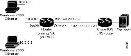
The Windows 2000 Client #1 establishes an IPsec-protected L2TP tunnel to the Cisco IOS LNS router. The Windows 2000 Client #1 and the Cisco IOS LNS router recognize that there is a NAT router located between them and the NAT router is enabled with IPsec and NAT-Traversal (NAT-T). The Windows 2000 Client #1 attempts to establish an IPsec security association (SA) and requests a transport mode (which it does by default) with proxies from 10.0.0.2, its local address, to 209.265.200.231, the Cisco IOS LNS router's address.
In transport mode, NAT, running on the router, translates all outgoing connections (including 10.0.0.2) to its outside IP address (209.265.200.232), at which the address the traffic arrives. However, NAT cannot modify the L2TP port designation (1701), which is protected by the IPsec encrypted area. So, the local address now is 209.265.200.231, the remote address the 209.265.200.232 and the remote port is 1701. The traffic that matches the tunnel 209.265.200.231, port 1701 is sent to the Windows 2000 Client #1.
Windows 2000 Client #2 establishes an IPsec-protected L2TP tunnel to the Cisco IOS LNS router and NAT translates outgoing connections to its outside IP address (209.265.200.232) again, NAT cannot modify the L2TP port designation (1701) similar to Windows Client #1. The traffic that matches tunnel 209.265.200.231, port 1701 is now sent to Windows 2000 Client #2. which ends Windows Client #1's connection with the Cisco IOS LNS router since it is no longer receiving traffic.
L2TP IPsec Support for NAT and PAT Windows Clients Feature Enabled
When the L2TP IPsec Support for NAT and PAT Windows Clients feature is enabled, IPsec can translate the L2TP ports after decryption. This feature allows IPsec to map traffic from different hosts to different source ports. L2TP can now distinguish between traffic destined for multiple Windows 2000 clients.
When an security association (SA) is created, a translated port is assigned to the SA. This port is client-specific. The same port is used for any new SA created by that client. When an encrypted request is received and decrypted, the source port is translated from the standard value 1701 to a client specific value. The request with the translated port is then forwarded to L2TP.
As shown in the above figure, with port address translation enabled, the Windows 2000 Client #1 is assigned to the translated port number 1024, and Windows 2000 Client #2 is assigned to the translated port number 1025.
When L2TP sends the reply packet, it uses the translated port number and creates a packet to that destination port. IPsec uses the destination port number to select the SA with which to encrypt the packet. Before encrypting the packet, IPsec translates the destination port back to the standard port number 1701, which the Windows 2000 client expects. IPsec encrypts the packet either with the SA to Windows 2000 Client #1 if the destination port is 1024 or with the SA to Windows 2000 Client #2 if the destination port is 1025. The traffic is now sent to the appropriate client, and multiple Windows clients can be connected to a Cisco IOS LNS router through a NAT server at the same time.
The connection is maintained until one of the following actions occurs:
How to Enable L2TP IPsec Support for NAT and PAT Windows Clients
Enabling L2TP IPsec Support
DETAILED STEPS
Configuration Examples for L2TP IPsec Support for NAT and PAT Windows Clients
Example: Dynamic Map Configuration
The following example shows how to enable the L2TP IPsec Support for NAT and PAT Windows Clients feature for a dynamic crypto map:
!

version 12.3
service timestamps debug datetime msec
service timestamps log datetime msec
no service password-encryption
!
hostname 72_LNS
!
boot-start-marker
boot-end-marker
!
aaa new-model
!
!
aaa authentication ppp default local
aaa session-id common
ip subnet-zero
!
!
no ip cef
no ip domain lookup
ip domain name cisco.com
ip dhcp excluded-address 198.51.100.1
ip dhcp excluded-address 198.51.100.10
!
!
ip vrf VPN
 rd 1:1
!
! Enable virtual private networking.
vpdn enable
vpdn ip udp ignore checksum
!
! Default L2TP VPDN group
vpdn-group L2TP
!
! Enables the LNS to accept dial in requests; specifies L2TP as the tunneling
! protocol; specifies the number of the virtual templates used to clone
! virtual-access interfaces.
 accept-dialin
  protocol l2tp
  virtual-template 1

! Disables L2TP tunnel authentication.
no l2tp tunnel authentication
!
!
crypto keyring L2TP
  pre-shared-key address 0.0.0.0 0.0.0.0 key *****
!
!Defines an Internet Key Exchange (IKE) policy and assigns priority 1.
crypto isakmp policy 1
 encr aes
 authentication pre-share
 group 14
 lifetime 3600
!
crypto isakmp key cisco hostname w2k01
crypto isakmp keepalive 3600
!
crypto ipsec security-association lifetime seconds 600
!
!Defines a transform set.
crypto ipsec transform-set TS1 esp-aes esp-sha-hmac
 mode transport
!
! Names the dynamic crypto map entry and enters crypto map configuration mode; Enables
! L2TP--IPSec support; Specifies which transform sets can be used with the crypto map
! entry.
crypto dynamic-map DYN_MAP 10
 set nat demux
 set transform-set TS1!
!
crypto map CRYP_MAP 6000 ipsec-isakmp dynamic DYN_MAP
!
interface Loopback0
 ip address 198.51.100.1 255.255.255.0
!
interface FastEthernet0/0
 ip address 198.51.100.110 255.255.255.0
 no ip route-cache
 duplex full
 speed 100
 crypto map CRYP_MAP
!
interface FastEthernet0/1
 ip address 198.51.100.1 255.255.255.0
 duplex full
 speed 100
!
interface FastEthernet2/0
 ip address 172.19.192.138 255.255.255.0
 duplex full
!
interface Virtual-Template1
 ip unnumbered Loopback0
 peer default ip address pool POOL
 ppp mtu adaptive
 ppp authentication chap ms-chap
!
router ospf 1
 log-adjacency-changes
 redistribute static subnets
 network 198.51.100.10 0.0.0.255 area 0
!
ip local pool POOL 198.51.100.100 198.51.100.110
ip classless
ip route 171.0.0.0 255.0.0.0 172.19.192.1
!
no ip http server
no ip http secure-server
!
!
control-plane
!
gatekeeper
 shutdown!
!
line con 0
 exec-timeout 0 0
 logging synchronous
 stopbits 1
line aux 0
 stopbits 1
line vty 0 4
!
end
Additional References
Related Documents
Technical Assistance
|
Description |
Link |
|---|---|
|
The Cisco Support and Documentation website provides online resources to download documentation, software, and tools. Use these resources to install and configure the software and to troubleshoot and resolve technical issues with Cisco products and technologies. Access to most tools on the Cisco Support and Documentation website requires a Cisco.com user ID and password. |
Feature Information for L2TP IPsec Support for NAT and PAT Windows Clients
The following table provides release information about the feature or features described in this module. This table lists only the software release that introduced support for a given feature in a given software release train. Unless noted otherwise, subsequent releases of that software release train also support that feature.
Use Cisco Feature Navigator to find information about platform support and Cisco software image support. To access Cisco Feature Navigator, go to www.cisco.com/go/cfn. An account on Cisco.com is not required.
| Table 1 | Feature Information for L2TP IPsec Support for NAT and PAT Windows Clients |
|
Feature Name |
Releases |
Feature Information |
|---|---|---|
|
L2TP IPsec Support for NAT and PAT Windows Clients |
12.3(11)T4 12.4(1) |
The L2TP IPsec Support for NAT and PAT Windows Clients feature allows mulitple Windows client to connect to an IPsec-enabled Cisco IOS Layer 2 Tunneling Protocol (L2TP) Network Server (LNS) through a network address translation (NAT) or port address translation (PAT) server. In 12.3(11)T4, this feature was introduced. The following commands were modified by this feature: crypto dynamic-map, crypto map, set nat demux, show crypto dynamic-map, show crypto map, show crypto ipsec sa. |
Cisco and the Cisco logo are trademarks or registered trademarks of Cisco and/or its affiliates in the U.S. and other countries. To view a list of Cisco trademarks, go to this URL: www.cisco.com/go/trademarks. Third-party trademarks mentioned are the property of their respective owners. The use of the word partner does not imply a partnership relationship between Cisco and any other company. (1110R)
Any Internet Protocol (IP) addresses and phone numbers used in this document are not intended to be actual addresses and phone numbers. Any examples, command display output, network topology diagrams, and other figures included in the document are shown for illustrative purposes only. Any use of actual IP addresses or phone numbers in illustrative content is unintentional and coincidental.