
 Feedback
Contents
- Stateful Failover for IPsec
- Finding Feature Information
- Prerequisites for Stateful Failover for IPsec
- Restrictions for Stateful Failover for IPsec
- Information About Stateful Failover for IPsec
- Supported Deployment Scenarios Stateful Failover for IPsec
- IPsec Stateful Failover for Remote Access Connections
- Dead Peer Detection with IPsec High Availability
- How to Use Stateful Failover for IPsec
- Enabling HSRP IP Redundancy and a Virtual IP Address
- Troubleshooting Tips
- Examples
- What to Do Next
- Enabling SSO
- SSO Interacting with IPsec and IKE
- Troubleshooting Tips
- Examples
- What to Do Next
- Configuring Reverse Route Injection on a Crypto Map
- Configuring RRI on Dynamic Crypto Map
- Configuring RRI on a Static Crypto Map
- What to Do Next
- Enabling Stateful Failover for IKE and IPsec
- Enabling Stateful Failover for IKE
- Enabling Stateful Failover for IPsec
- Troubleshooting Tips
- Examples
- Enabling Stateful Failover for Tunnel Protection
- Examples
- What to Do Next
- Protecting SSO Traffic
- Managing and Verifying High Availability Information
- Managing Anti-Replay Intervals
- Managing and Verifying HA Configurations
- Examples
- Configuration Examples for Stateful Failover
- Example: Configuring Stateful Failover for IPsec
- Example: Configuring Stateful Failover for IPsec for an Easy VPN Server
- Additional References
- Feature Information for Stateful Failover for IPsec
Stateful Failover for IPsec
Stateful failover for IP Security (IPsec) enables a router to continue processing and forwarding IPsec packets after a planned or unplanned outage occurs. Customers employ a backup (secondary) router that automatically takes over the tasks of the active (primary) router if the active router loses connectivity for any reason. This failover process is transparent to users and does not require adjustment or reconfiguration of any remote peer.
Stateful failover for IPsec is designed to work in conjunction with stateful switchover (SSO) and Hot Standby Routing Protocol (HSRP). HSRP provides network redundancy for IP networks, ensuring that user traffic immediately and transparently recovers from failures in network edge devices or access circuits. That is, HSRP monitors both the inside and outside interfaces so that if either interface goes down, the whole router is deemed to be down and the ownership of Internet Key Exchange (IKE) and IPsec security associations (SAs) is passed to the standby router (which transitions to the HSRP active state). SSO allows the active and standby routers to share IKE and IPsec state information so both routers have enough information to become the active router at any time. To configure stateful failover for IPsec, a network administrator must enable HSRP, assign a virtual IP address (VIP), and enable SSO.
 Note | Security threats, as well as the cryptographic technologies to help protect against them, are constantly changing. For more information about the latest Cisco cryptographic recommendations, see the Next Generation Encryption (NGE) white paper. |
- Finding Feature Information
- Prerequisites for Stateful Failover for IPsec
- Restrictions for Stateful Failover for IPsec
- Information About Stateful Failover for IPsec
- How to Use Stateful Failover for IPsec
- Configuration Examples for Stateful Failover
- Additional References
- Feature Information for Stateful Failover for IPsec
Finding Feature Information
Your software release may not support all the features documented in this module. For the latest caveats and feature information, see Bug Search Tool and the release notes for your platform and software release. To find information about the features documented in this module, and to see a list of the releases in which each feature is supported, see the feature information table at the end of this module.
Use Cisco Feature Navigator to find information about platform support and Cisco software image support. To access Cisco Feature Navigator, go to www.cisco.com/go/cfn. An account on Cisco.com is not required.
Prerequisites for Stateful Failover for IPsec
Complete, Duplicate IPsec and IKE Configuration on the Active and Standby Devices
This document assumes that you have a complete IKE and IPsec configuration. (This document describes only how to add stateful failover to a working IPsec configuration.)
The IKE and IPsec configuration that is set up on the active device must be duplicated on the standby device. That is, the crypto configuration must be identical with respect to Internet Security Association and Key Management Protocol (ISAKMP) policy, ISAKMP keys (preshared), IPsec profiles, IPsec transform sets, all crypto map sets that are used for stateful failover, all access control lists (ACLs) that are used in match address statements on the crypto map sets, all AAA configurations used for crypto, client configuration groups, ip local pools used for crypto, and ISAKMP profiles.
Device Requirements
- Stateful failover for IPsec requires that your network contains two identical routers that are available to be either the primary or secondary device. Both routers should be the same type of device, have the same CPU and memory, and have either no encryption accelerator or identical encryption accelerators.
- This feature is currently supported only on a limited number of platforms. To check the latest platform support, go to Cisco Feature Navigator at http://tools.cisco.com/ITDIT/CFN/jsp/index.jsp .
Restrictions for Stateful Failover for IPsec
When configuring redundancy for a virtual private network (VPN), the following restrictions exist:
- Both the active and standby devices must run the identical version of the Cisco IOS software, and both the active and standby devices must be connected via hub or switch.
-
The Cisco Integrated Services Routers (ISRs) and the VPN modules that support stateful failover for IPsec are as follows:
- The AIM-VPN/BPII-PLUS and AIM-VPN/SSL-1 hardware encryption modules are supported in a Cisco 1841 router.
- The AIM-VPN/EPII-Plus and AIM-VPN/SSL-2 hardware encryption modules are supported in Cisco 2801, 2811, 2821 and 2851 routers.
- The AIM-VPN/EPII+ and AIM-VPN/SSL-3 hardware encryption modules are supported in a Cisco 3825 router.
- The AIM-VPN/HPII+ and AIM-VPN/SSL3 hardware encryption modules are supported in a Cisco 3845 router.
- The VPN Acceleration Module (VAM) and VAM2 hardware encryption modules are supported in a Cisco 7200 series router.
- Only "box-to-box" failover is supported; that is, intrachassis failover is currently not supported.
- WAN interfaces between the active (primary) router and the standby (secondary) router are not supported. (HSRP requires inside interfaces and outside interfaces to be connected via LANs.)
- Load balancing is not supported; that is, no more than one device in a redundancy group can be active at any given time.
- Stateful failover of IPsec with Layer 2 Tunneling Protocol (L2TP) i s not supported.
- Public key infrastructure (PKI) is not supported when used with stateful failover. (Only preshared keys for IKE are supported.)
- IKE keepalives are not supported. (Enabling this functionality will cause the connection to be torn down after the standby router assumes ownership control.) However, dead peer detection (DPD) and periodic DPD are supported.
- IPsec idle timers are not supported when used with stateful failover.
- A stateful failover crypto map applied to an interface in a virtual route forwarding (VRF) instance is not supported. However, VRF-aware IPsec features are supported when a stateful failover crypto map is applied to an interface in the global VRF.
- Stateful failover is not compatible or interoperable with the State Synchronization Protocol (SSP) version of stateful failover (which is available in Cisco IOS Release 12.2YX1 and Cisco IOS Release 12.2SU).
Information About Stateful Failover for IPsec
- Supported Deployment Scenarios Stateful Failover for IPsec
- IPsec Stateful Failover for Remote Access Connections
- Dead Peer Detection with IPsec High Availability
Supported Deployment Scenarios Stateful Failover for IPsec
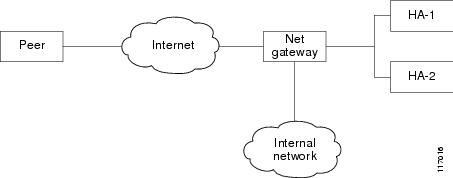
It is recommended that you implement IPsec stateful failover in one of the following recommended deployment scenarios--a single interface scenario or a dual interface scenario.
In a single interface scenario, the VPN gateways use one LAN connection for both encrypted traffic arriving from remote peers and decrypted traffic flowing to inside hosts (see the figure below). The single interface design allows customers to save money on router ports and subnets. This design is typically used if all traffic flowing in and out of the organization does not traverse the VPN routers.
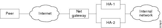
In a dual interface scenario, a VPN gateway has more than one interface, enabling traffic to flow in and out of the router via separate interfaces (see the figure below ). This scenario is typically used if traffic flowing in and out of a site must traverse the routers, so the VPN routers will provide the default route out of the network.
The table below lists the functionality available in both a single interface scenario and a dual interfaces scenario.
| Table 1 | IPsec StateFul Failover: Single and Dual Interface Functionality Overview |
|
Single Interface |
Dual Interface |
|---|---|
|
Route Injection |
|
|
Routes must be injected to provide the devices that are behind the VPN gateways with a next hop for traffic that requires encryption. Stateful failover for IPsec typically requires routes to be injected for this network topology. |
If the VPN gateways are not the logical next hop for devices inside the network, the routes must be created and injected into the routing process. Thus, traffic that is returning from inside the network can be sent back to the VPN routers for IPsec services before it is sent out. A virtual IP (VIP) address cannot be used as the advertiser of routing updates, so flows must be synchronized via the injected routes. If the VPN gateways are the next hop (default route) for all devices inside the network, the VIP address that is used on the inside interfaces can be used as the next hop. Thus, injection of the VPN routes is not required. However, static routes on inside hosts must be used to direct the routes to the next hop VIP address. |
|
HSRP Configuration |
|
|
The role of HSRP is simplified in a single interface design because if the only interface is disabled, the entire device is deemed unavailable. This functionality helps to avoid some of the routing considerations to be discussed in the next scenario. |
Because each interface pair functions independently, you should configure HSRP so that multiple pairs of interfaces can be tracked. (That is, HSRP should not be configured on only one pair of interfaces or on both pairs of interfaces without each pair mutually tracking each other.) Mutual tracking means that if the outside interface does fail, the inside interface on the same router will also be deemed down, allowing for complete router failover to the secondary router. |
|
Secure State Information |
|
|
If secured-state information is passed between routers, the information is passed over the same interface as all other traffic. |
The router has a separate inside and outside interface; thus, the inside interface can be used as a more secure channel for the exchange of state information. |
|
Firewall Configuration |
|
|
The VPN gateways can sit in front of the firewall or behind the firewall. |
VPN gateways may sit behind or in front of a firewall, a firewall can be installed in parallel to the VPN gateways. |
IPsec Stateful Failover for Remote Access Connections
The main difference between a remote access and a LAN-to-LAN connection is the use of Xauth and mode-config. IKE Xauth is often used to authenticate the user. IKE mode-config is often used to push security policy from the hub (concentrator) router to the user's IPsec implementation. Mode-config is also typically used to assign an internal company network IP address to a user.
In addition to the differences between a remote access configuration and a LAN-to-LAN configuration, you should note the following remote-access-server-specific functions:
-
Assigned IP address--The IP address can be assigned to the client via one of the following options:
- Local IP pools. For local IP pools, the administrator must first configure identical local IP address pools on each router in the high availability (HA) pair (via the ip local pool client-address-poolcommand). This pool name can be applied in one of two places--in a group policy via the crypto isakmp client configuration group group-name (and the submode command pool pool-name) or in a client configuration via the crypto isakmp client configuration address-pool local local-pool command.
- RADIUS-assigned address. If you are using RADIUS authentication and the RADIUS server returns the Framed-IP-Address attribute, the concentrator will always assign that address to the client. It is recommended that you refer to your RADIUS server vendor's documentation, especially for vendors that allow you to configure address pools on the RADIUS server. Typically those servers require crypto accounting to work properly.
To enable accounting on the HA pair, you should issue the following commands on both Active and Standby devices: aaa accounting network radius-accounting start-stop group radius then apply radius-accounting either to the crypto isakmp profile or the crypto map set.
- RADIUS NAS-IP address--The HA pair should appear as a single device to the RADIUS server. Thus, both HA routers must communicate with the RADIUS server using the same IP address. However, when communicating with the RADIUS server, the router must use a physical IP address, not a virtual IP (VIP) address as the NAS-IP address of the router. To configure the RADIUS NAS-IP address for the HA pair, you must configure the same loopback address in the HA pair via interface loopback ip addresscommand; thereafter, you must issue the ip radius source-interface loopback command in the HA pair. Finally, add the new loopback IP address to the RADIUS servers configuration so the RADIUS server can process requests from the HA pair.
For additional information on how to configure IPsec stateful failover for a remote access connection, see the section " Configuring IPSec Stateful Failover for an Easy VPN Server: Example " in this document.
Dead Peer Detection with IPsec High Availability
To configure Dead Peer Detection (DPD) with IPsec High Availability (HA), it is recommended that you use a value other than the default (2 seconds). A keepalive time of 10 seconds with 5 retries seems to work well with HA because of the time it takes for the router to get into active mode.
To configure DPD with IPsec HA, use the crypto isakmp keepalive command.
How to Use Stateful Failover for IPsec
This section contains the following procedures:
- Enabling HSRP: IP Redundancy and a Virtual IP Address, page 6 (required)
- Enabling SSO, page 9 (required)
- Configuring Reverse Route Injection on a Crypto Map, page 13 (required)
- Enabling Stateful Failover for IKE and IPSec, page 15 (required)
- Protecting SSO Traffic, page 18 (optional)
- Managing and Verifying High Availability Information, page 20 (optional)
- Enabling HSRP IP Redundancy and a Virtual IP Address
- Enabling SSO
- Configuring Reverse Route Injection on a Crypto Map
- Enabling Stateful Failover for IKE and IPsec
- Protecting SSO Traffic
- Managing and Verifying High Availability Information
Enabling HSRP IP Redundancy and a Virtual IP Address
HSRP provides two services--IP redundancy and a VIP address. Each HSRP group may provide either or both of these services. IPsec stateful failover uses the IP redundancy services from only one HSRP standby group. It can use the VIP address from one or more HSRP groups. Use the following task to configure HSRP on the outside and inside interfaces of the router.
Note | Perform this task on both routers (active and standby) and of both interfaces on each router. |
Note | You must perform at least one of the prerequisite steps for correct HSRP operation. |
If a switch connects the active and standby routers, you must perform one of the following steps to ensure that the correct settings are configured on that switch:
- Enable the spanning-tree portfast command on every switch port that connects to a HSRP-enabled router interface.
- Disable the Spanning Tree Protocol (STP) on the switch only if your switch does not connect to other switches. Disabling spanning tree in a multi-switch environment may cause network instability.
- Enable the standby delay minimum [min-delay] reload [reload-delay] command if you do not have access to the switch. The reload-delay argument should be set to a value of at least 120 seconds. This command must be applied to all HSRP interfaces on both routers.
For more information on HSRP instability, see the "Avoiding HSRP Instability in a Switching Environment with Various Router Platforms" technical note.
DETAILED STEPS
Troubleshooting Tips
To help troubleshoot possible HSRP-related configuration problems, issue any of the following HSRP-related debug commands--debug standby errors, debug standby events, and debug standby packets [terse].
Enabling SSO
Use this task to enable SSO, which is used to transfer IKE and IPsec state information between two routers.
SSO Interacting with IPsec and IKE
SSO is a method of providing redundancy and synchronization for many Cisco IOS applications and features. SSO is necessary for IPsec and IKE to learn about the redundancy state of the network and to synchronize their internal application state with their redundant peers.
- You should configure HSRP before enabling SSO.
-
To avoid losing SCTP communication between peers, be sure to include the following commands to the local address section of the SCTP section of the IPC configuration:
- retransmit-timeout retran-min [msec] retra-max [msec]
- path-retransmit max-path-retries
- assoc-retransmit retries
DETAILED STEPS
| Command or Action | Purpose | |||
|---|---|---|---|---|
Step 1 |
enable
Example: Router> enable |
Enables privileged EXEC mode.
| ||
Step 2 |
configure
terminal
Example: Router# configure terminal |
Enters global configuration mode. | ||
Step 3 |
redundancy
inter-device
Example: Router(config)# redundancy inter-device |
Configures redundancy and enters inter-device configuration mode. To exit inter-device configuration mode, use the exit command. To remove all inter-device configuration, use the no form of the command. | ||
Step 4 |
scheme
standby
standby-group-name
Example: Router(config-red-interdevice)# scheme standby HA-out |
Defines the redundancy scheme that is to be used. Currently, "standby" is the only supported scheme.
| ||
Step 5 |
exit
Example: Router(config-red-interdevice)# exit |
Exits inter-device configuration mode. | ||
Step 6 |
ipc
zone
default
Example: Router(config)# ipc zone default |
Configures the inter-device communication protocol, Inter-Process Communication (IPC), and enters IPC zone configuration mode. Use this command to initiate the communication link between the active router and standby router. | ||
Step 7 |
association
1
Example: Router(config-ipczone)# association 1 |
Configures an association between the two devices and enters IPC association configuration mode. | ||
Step 8 |
protocol
sctp
Example: Router(config-ipczone-assoc)# protocol sctp |
Configures Stream Control Transmission Protocol (SCTP) as the transport protocol and enters SCTP protocol configuration mode. | ||
Step 9 |
local-port
local-port-number
Example: Router(config-ipc-protocol-sctp)# local-port 5000 |
Defines the local SCTP port number that is used to communicate with the redundant peer and puts you in IPC transport - SCTP local configuration mode.
| ||
Step 10 |
local-ip
device-real-ip-address
[device-real-ip-address2 Example: Router(config-ipc-local-sctp)# local-ip 10.0.0.1 |
Defines at least one local IP address that is used to communicate with the redundant peer. The local IP addresses must match the remote IP addresses on the peer router. There can be either one or two IP addresses, which must be in the global VRF. A virtual IP address cannot be used. | ||
Step 11 |
retransmit-timeout
retran-min
[msec] retra-max [msec] Example: Router(config-ipc-local-sctp)# retransmit-timeout 300 10000 |
Configures the maximum amount of time, in milliseconds, that SCTP will wait before retransmitting data.
| ||
Step 12 |
path-retransmit
max-path-retries
Example: Router(config-ipc-local-sctp)# path-retransmit 10 |
Configures the number of consecutive retransmissions SCTP will perform before failing a path within an association.
| ||
Step 13 |
assoc-
retransmit retries
Example: Router(config-ipc-local-sctp)# assoc -retransmit 10 |
Configures the number of consecutive retransmissions SCTP will perform before failing an association.
| ||
Step 14 |
exit
Example: Router(config-ipc-local-sctp)# exit |
Exits IPC transport - SCTP local configuration mode. | ||
Step 15 |
remote-port
remote-port-number
Example: Router(config-ipc-protocol-sctp)# remote-port 5000 |
Defines the remote SCTP port number that is used to communicate with the redundant peer and puts you in IPC transport - SCTP remote configuration mode.
| ||
Step 16 |
remote-ip
peer-real-ip-address
[peer-real-ip-address2 Example: Router(config-ipc-remote-sctp)# remote-ip 10.0.0.2 |
Defines at least one remote IP address of the redundant peer that is used to communicate with the local device. All remote IP addresses must refer to the same device. A virtual IP address cannot be used. |
Troubleshooting Tips
To help troubleshoot possible SSO-related configuration problems, issue the debug redundancy command.
Configuring Reverse Route Injection on a Crypto Map
You should configure RRI on all existing crypto maps that you want to use with stateful failover. RRI is used with stateful failover so routers on the inside network can learn about the correct path to the current active device. When failover occurs, the new active device injects the RRI routes into its IP routing table and sends out routing updates to its routing peers.
Use one of the following tasks to configure RRI on a dynamic or static crypto map.
- Configuring RRI on Dynamic Crypto Map, page 13
- Configuring RRI on a Static Crypto Map, page 14
Configuring RRI on Dynamic Crypto Map
Dynamic crypto map entries, like regular static crypto map entries, are grouped into sets. A set is a group of dynamic crypto map entries all with the same dynamic map name but each with a different dynamic sequence number. Each member of the set may be configured for RRI.
DETAILED STEPS
| Command or Action | Purpose | |
|---|---|---|
Step 1 |
enable
Example: Router> enable |
Enables privileged EXEC mode.
|
Step 2 |
configure
terminal
Example: Router# configure terminal |
Enters global configuration mode. |
Step 3 |
crypto
dynamic-map
map-name
seq-num
Example: Router(config)# crypto dynamic-map mymap 10 |
Creates a dynamic crypto map entry and enters crypto map configuration mode. |
Step 4 |
reverse-route
Example: Router(config-crypto-map)# reverse-route |
Enables RRI for a dynamic crypto map. |
Configuring RRI on a Static Crypto Map
Static crypto map entries are grouped into sets. A set is a group of static crypto map entries all with the same static map name but each with a different sequence number. Each static crypto map in the map set can be configured for RRI. Use this task to configure RRI on a static crypto map.
DETAILED STEPS
| Command or Action | Purpose | |
|---|---|---|
Step 1 |
enable
Example: Router> enable |
Enables privileged EXEC mode.
|
Step 2 |
configure
terminal
Example: Router# configure terminal |
Enters global configuration mode. |
Step 3 |
crypto
map
map-name seq-num
ipsec-isakmp
Example: Router(config)# crypto map to-peer-outside 10 ipsec-isakmp |
Enters crypto map configuration mode and creates or modifies a crypto map entry. |
Step 4 |
reverse-route
Example: Router(config-crypto-map)# reverse-route |
Dynamically creates static routes based on crypto ACLs. |
Examples
The following example shows how to configure RRI on the static crypto map "to-peer-outside":
crypto map to-peer-outside redundancy replay-interval inbound 1000 outbound 10000 crypto map to-peer-outside 10 ipsec-isakmp set peer 209.165.200.225 set transform-set trans1 match address peer-outside reverse-route
Enabling Stateful Failover for IKE and IPsec
Use the following tasks to configure stateful failover for IPsec, IKE, and tunnel protection:
- Enabling Stateful Failover for IKE, page 15
- Enabling Stateful Failover for IPSec, page 15
- Enabling Stateful Failover for Tunnel Protection, page 17
- Enabling Stateful Failover for IKE
- Enabling Stateful Failover for IPsec
- Enabling Stateful Failover for Tunnel Protection
- What to Do Next
Enabling Stateful Failover for IKE
There is no specific command-line interface (CLI) necessary to enable stateful failover for IKE. It is enabled for a particular VIP address when a stateful failover crypto map is applied to an interface.
Enabling Stateful Failover for IPsec
Use this task to enable stateful failover for IPsec. All IPsec state information is transferred from the active router to the standby router via the SSO redundancy channel that was specified in the task " Enabling SSO ."
DETAILED STEPS
| Command or Action | Purpose | |||
|---|---|---|---|---|
Step 1 |
enable
Example: Router> enable |
Enables privileged EXEC mode.
| ||
Step 2 |
configure
terminal
Example: Router# configure terminal |
Enters global configuration mode. | ||
Step 3 |
interface
typenumber Example: Router(config)# interface Ethernet 0/0 |
Defines an interface that has already been configured for redundancy and enters interface configuration mode. | ||
Step 4 |
crypto map map-name [redundancy standby-group-name [stateful]]
Example: Router(config-if)# crypto map to-peer-outside redundancy HA-out stateful |
Binds the crypto map on the specified interface to the redundancy group.
This crypto map will use the same VIP address for both IKE and IPsec to communicate with peers. |
Troubleshooting Tips
To help troubleshoot possible IPsec HA-related problems, issue the debug crypto ipsec ha [detail] [update] command.
Examples
The following example shows how to configure IPsec stateful failover on the crypto map "to-peer-outside":
interface Ethernet0/0 ip address 209.165.201.1 255.255.255.224 standby 1 ip 209.165.201.3 standby 1 preempt standby 1 name HA-out standby 1 track Ethernet1/0 crypto map to-peer-outside redundancy HA-out stateful
Enabling Stateful Failover for Tunnel Protection
Use an existing IPsec profile to configure stateful failover for tunnels using IPsec. (You do not configure the tunnel interface as you would with a crypto map configuration.)
Note | The tunnel source address must be a VIP address, and it must not be an interface name. > |
DETAILED STEPS
| Command or Action | Purpose | |||
|---|---|---|---|---|
Step 1 |
enable
Example: Router> enable |
Enables privileged EXEC mode.
| ||
Step 2 |
configure
terminal
Example: Router# configure terminal |
Enters global configuration mode. | ||
Step 3 |
crypto ipsec profile name
Example: Router(config)# crypto ipsec profile peer-profile |
Defines the IPsec parameters that are to be used for IPsec encryption between two routers and enters crypto map configuration mode. | ||
Step 4 |
redundancy standby-group-name stateful
Example: Router( config-crypto-map )# redundancy HA-out stateful |
Configures stateful failover for tunnels using IPsec. | ||
Step 5 |
exit
Example: Router(config-crypto-map)# exit |
Exits crypto map configuration mode. | ||
Step 6 |
interface
tunnel
number
Example: Router(config)# interface tunnel 5 |
Configures a tunnel interface and enters interface configuration mode
| ||
Step 7 |
tunnel
protection
ipsec
profile
name
Example: Router(config-if)# tunnel protection ipsec profile catprofile |
Associates a tunnel interface with an IPsec profile. name --Specifies the name of the IPsec profile; this value must match the name specified in the crypto ipsec profile namecommand. | ||
Step 8 |
tunnel
source
virtual
ip-address
Example: Router(config-if)# tunnel source 10.1.1.1 |
Sets source address for a tunnel interface.
|
Examples
The following example shows how to configure stateful failover for tunnel protection:
crypto ipsec profile peer-profile redundancy HA-out stateful interface Tunnel1 ip unnumbered Loopback0 tunnel source 209.165.201.3 tunnel destination 10.0.0.5 tunnel protection ipsec profile peer-profile ! interface Ethernet0/0 ip address 209.165.201.1 255.255.255.224 standby 1 ip 209.165.201.3 standby 1 name HA-out
Protecting SSO Traffic
Use this task to secure a redundancy group via an IPsec profile. To configure SSO traffic protection, the active and standby devices must be directly connected to each other via Ethernet networks.
The crypto maps that are automatically generated when protecting SSO traffic are applied to each interface, which corresponds to an IP address that was specified via the local-ip command. Traffic destined for an IP address that was specified via the remote-ip command is forced out of the crypto-map-configured interface via an automatically created static host route.
Note | If you are certain that the SSO traffic between the redundancy group runs on a physically secure interface, you do not have to configure SSO traffic protection. |
Note | Security threats, as well as the cryptographic technologies to help protect against them, are constantly changing. For more information about the latest Cisco cryptographic recommendations, see the Next Generation Encryption (NGE) white paper. |
DETAILED STEPS
| Command or Action | Purpose | |
|---|---|---|
Step 1 |
enable
Example: Router> enable |
Enables privileged EXEC mode. |
Step 2 |
configure
terminal
Example: Router# configure terminal |
Enters global configuration mode. |
Step 3 |
crypto
isakmp
key
keystring
address
peer-address
Example: Router(config)# crypto isakmp key abc123 address 0.0.0.0 0.0.0.0 |
Configures a preshared authentication key. |
Step 4 |
crypto
ipsec
transform-set
transform-set-name
transform-set-list
Example: Router(config)# crypto ipsec transform-set trans2 ah-sha-hmac esp-aes |
Configures a transform set that defines the packet format and cryptographic algorithms used for IPsec. |
Step 5 | crypto
ipsec
profile
profile-name
Example: Router(config)# crypto ipsec profile sso-secure |
Defines an IPsec profile that describes how the traffic will be protected and enters crypto map configuration mode. |
Step 6 |
set
transform-set
transform-set-name
Example: Router(config-crypto-map)# set transform-set trans2 |
Specifies which transform sets can be used with the IPsec profile. |
Step 7 |
exit
Example: Router(config-crypto-map)# exit |
Exits crypto map configuration mode and returns to global configuration mode. |
Step 8 |
redundancy
inter-device
Example: Router(config)# redundancy inter-device |
Configures redundancy and enters inter-device configuration mode. |
Step 9 |
security
ipsec
profile-name
Example: Router(config-red-interdevice)# security ipsec sso-secure |
Applies the IPsec profile to the redundancy group communications, protecting all SSO traffic that is passed between the active and standby devices. |
Examples
The following example shows how to configure SSO traffic protection:
crypto isakmp key abc123 address 0.0.0.0 0.0.0.0 no-xauth ! crypto ipsec transform-set trans2 ah-sha-hmac esp-aes ! crypto ipsec profile sso-secure set transform-set trans2 ! redundancy inter-device scheme standby HA-out security ipsec sso-secure
Managing and Verifying High Availability Information
Use any of the following optional tasks to secure and manage your high availability configurations:
- Managing Anti-Replay Intervals, page 21
- Managing and Verifying HA Configurations, page 22
Managing Anti-Replay Intervals
Use this optional task to modify the interval in which an IP redundancy-enabled crypto map forwards anti-replay updates from the active router to the standby router.
DETAILED STEPS
| Command or Action | Purpose | |
|---|---|---|
Step 1 |
enable
Example: Router> enable |
Enables privileged EXEC mode.
|
Step 2 |
configure
terminal
Example: Router# configure terminal |
Enters global configuration mode. |
Step 3 | crypto map map-name redundancy replay-interval inbound in-value outbound out-value
Example: Router(config)# crypto map to-peer-outside redundancy replay-interval inbound 1000 outbound 10000 |
Modifies the interval at which inbound and outbound replay counters are passed from an active device to a standby device.
|
Examples
The following example shows how to modify replay counter intervals between the active and standby devices on the crypto map "to-peer-outside":
crypto map to-peer-outside redundancy replay-interval inbound 1000 outbound 10000 crypto map to-peer-outside 10 ipsec-isakmp set peer 209.165.200.225 set transform-set trans1 match address peer-outside
Managing and Verifying HA Configurations
Use any of the steps within this optional task to display and verify the high availability configurations.
DETAILED STEPS
| Command or Action | Purpose | |
|---|---|---|
Step 1 |
enable
Example: Router> enable |
Enables privileged EXEC mode.
|
Step 2 |
show
redundancy
[states |
inter-device]
Example: Router# show redundancy states |
Displays the current state of SSO on the configured device. After the two devices have negotiated with each other, one device should show an "ACTIVE" state and the other device should show a "STANDBY HOT" state. |
Step 3 |
show
crypto
isakmp
sa
[active |
standby]
Example: Router# show crypto isakmp sa active |
Displays IKE SAs present on the device. An "ACTIVE" or "STDBY" state is shown for each SA.
|
Step 4 |
show
crypto
ipsec
sa
[active |
standby]
Example: Router# show crypto ipsec sa active |
Displays IPsec SAs present on the device. An "ACTIVE" or "STDBY" state is shown for each SA.
|
Step 5 |
show
crypto
session
[active |
standby
Example: Router# show crypto session active |
Displays crypto sessions that are currently present on the device. An "ACTIVE" or "STANDBY" state is shown as part of the state of each session, such as "UP-STANDBY." Only HA-enabled SAs are shown. |
Step 6 |
show
crypto
ha
Example: Router# show crypto ha |
Displays all virtual IP addresses that are currently in use by IPsec and IKE. |
Step 7 |
clear
crypto
isakmp
[active |
standby
Example: Router# clear crypto isakmp active |
Clears IKE SAs. When this command is issued on the standby device, all standby IKE SAs are resynchronized from the active device.
|
Step 8 |
clear
crypto
sa
[active |
standby
Example: Router# clear crypto sa active |
Clears IPsec SAs. When this command is issued on the standby device, all standby IPsec SAs are resynchronized from the active device.
|
Step 9 |
clear
crypto
session
[active |
standby
Example: Router# clear crypto session active |
Clears both IKE and IPsec SAs. Any standby SAs will resynchronize from the active device after they are cleared on the standby. Only HA-enabled SAs are cleared from the device. |
Examples
Verifying the Active Device
Router# show redundancy states my state = 13 -ACTIVE peer state = 8 -STANDBY HOT Mode = Duplex Unit ID = 0 Split Mode = Disabled Manual Swact = Enabled Communications = Up client count = 7 client_notification_TMR = 30000 milliseconds keep_alive TMR = 4000 milliseconds keep_alive count = 0 keep_alive threshold = 7 RF debug mask = 0x0 Router# show crypto isakmp sa active dst src state conn-id slot status 209.165.201.3 209.165.200.225 QM_IDLE 5 0 ACTIVE Router# show crypto ipsec sa active interface:Ethernet0/0 Crypto map tag:to-peer-outside, local addr 209.165.201.3 protected vrf:(none) local ident (addr/mask/prot/port):(192.168.0.1/255.255.255.255/0/0) remote ident (addr/mask/prot/port):(172.16.0.1/255.255.255.255/0/0) current_peer 209.165.200.225 port 500 PERMIT, flags={origin_is_acl,} #pkts encaps:3, #pkts encrypt:3, #pkts digest:3 #pkts decaps:4, #pkts decrypt:4, #pkts verify:4 #pkts compressed:0, #pkts decompressed:0 #pkts not compressed:0, #pkts compr. failed:0 #pkts not decompressed:0, #pkts decompress failed:0 #send errors 0, #recv errors 0 local crypto endpt.:209.165.201.3, remote crypto endpt.:209.165.200.225 path mtu 1500, media mtu 1500 current outbound spi:0xD42904F0(3559458032) inbound esp sas: spi:0xD3E9ABD0(3555306448) transform:esp-aes , in use settings ={Tunnel, } conn id:2006, flow_id:6, crypto map:to-peer-outside sa timing:remaining key lifetime (k/sec):(4586265/3542) HA last key lifetime sent(k):(4586267) ike_cookies:9263635C CA4B4E99 C14E908E 8EE2D79C IV size:16 bytes replay detection support:Y Status:ACTIVE inbound ah sas: spi: 0xF3EE3620(4092474912) transform: ah-sha-hmac , in use settings ={Tunnel, } conn id: 2006, flow_id: 6, crypto map: to-peer-outside sa timing: remaining key lifetime (k/sec): (4586265/3542) HA last key lifetime sent(k): (4586267) ike_cookies: 9263635C CA4B4E99 C14E908E 8EE2D79C replay detection support: Y Status: ACTIVE inbound pcp sas: outbound esp sas: spi: 0xD42904F0(3559458032) transform: esp-aes , in use settings ={Tunnel, } conn id: 2009, flow_id: 9, crypto map: to-peer-outside sa timing: remaining key lifetime (k/sec): (4586266/3542) HA last key lifetime sent(k): (4586267) ike_cookies: 9263635C CA4B4E99 C14E908E 8EE2D79C IV size: 16 bytes replay detection support: Y Status: ACTIVE outbound ah sas: spi: 0x75251086(1965363334) transform: ah-sha-hmac , in use settings ={Tunnel, } conn id: 2009, flow_id: 9, crypto map: to-peer-outside sa timing: remaining key lifetime (k/sec): (4586266/3542) HA last key lifetime sent(k): (4586267) ike_cookies: 9263635C CA4B4E99 C14E908E 8EE2D79C replay detection support: Y Status: ACTIVE outbound pcp sas:
Router# show crypto session active
Crypto session current status
Interface: Ethernet0/0
Session status: UP-ACTIVE
Peer: 209.165.200.225 port 500
IKE SA: local 209.165.201.3/500 remote 209.165.200.225/500 Active
IKE SA: local 209.165.201.3/500 remote 209.165.200.225/500 Active
IPSEC FLOW: permit ip host 192.168.0.1 host 172.16.0.1
Active SAs: 4, origin: crypto map
Router# show crypto ha
IKE VIP: 209.165.201.3
stamp: 74 BA 70 27 9C 4F 7F 81 3A 70 13 C9 65 22 E7 76
IPSec VIP: 209.165.201.3
IPSec VIP: 255.255.255.253
IPSec VIP: 255.255.255.254
Verifying the Standby Device
Router# show redundancy states my state = 8 -STANDBY HOT peer state = 13 -ACTIVE Mode = Duplex Unit ID = 0 Split Mode = Disabled Manual Swact = Enabled Communications = Up client count = 7 client_notification_TMR = 30000 milliseconds keep_alive TMR = 4000 milliseconds keep_alive count = 1 keep_alive threshold = 7 RF debug mask = 0x0 Router# show crypto isakmp sa standby dst src state conn-id slot status 209.165.201.3 209.165.200.225 QM_IDLE 5 0 STDBY Router# show crypto ipsec sa standby interface:Ethernet0/0 Crypto map tag:to-peer-outside, local addr 209.165.201.3 protected vrf:(none) local ident (addr/mask/prot/port):(192.168.0.1/255.255.255.255/0/0) remote ident (addr/mask/prot/port):(172.16.0.1/255.255.255.255/0/0) current_peer 209.165.200.225 port 500 PERMIT, flags={origin_is_acl,} #pkts encaps:0, #pkts encrypt:0, #pkts digest:0 #pkts decaps:0, #pkts decrypt:0, #pkts verify:0 #pkts compressed:0, #pkts decompressed:0 #pkts not compressed:0, #pkts compr. failed:0 #pkts not decompressed:0, #pkts decompress failed:0 #send errors 0, #recv errors 0 local crypto endpt.:209.165.201.3, remote crypto endpt.:209.165.200.225 path mtu 1500, media mtu 1500 current outbound spi:0xD42904F0(3559458032) inbound esp sas: spi:0xD3E9ABD0(3555306448) transform:esp-aes , in use settings ={Tunnel, } conn id:2012, flow_id:12, crypto map:to-peer-outside sa timing:remaining key lifetime (k/sec):(4441561/3486) HA last key lifetime sent(k):(4441561) ike_cookies:00000000 00000000 00000000 00000000 IV size:16 bytes replay detection support:Y Status:STANDBY inbound ah sas: spi:0xF3EE3620(4092474912) transform:ah-sha-hmac , in use settings ={Tunnel, } conn id:2012, flow_id:12, crypto map:to-peer-outside sa timing:remaining key lifetime (k/sec):(4441561/3486) HA last key lifetime sent(k):(4441561) ike_cookies:00000000 00000000 00000000 00000000 replay detection support:Y Status:STANDBY inbound pcp sas: outbound esp sas: spi:0xD42904F0(3559458032) transform:esp-aes , in use settings ={Tunnel, } conn id:2011, flow_id:11, crypto map:to-peer-outside sa timing:remaining key lifetime (k/sec):(4441561/3485) HA last key lifetime sent(k):(4441561) ike_cookies:00000000 00000000 00000000 00000000 IV size:16 bytes replay detection support:Y Status:STANDBY outbound ah sas: spi:0x75251086(1965363334) transform:ah-sha-hmac , in use settings ={Tunnel, } conn id:2011, flow_id:11, crypto map:to-peer-outside sa timing:remaining key lifetime (k/sec):(4441561/3485) HA last key lifetime sent(k):(4441561) ike_cookies:00000000 00000000 00000000 00000000 replay detection support:Y Status:STANDBY outbound pcp sas: Router# show crypto session standby Crypto session current status Interface:Ethernet0/0 Session status:UP-STANDBY Peer:209.165.200.225 port 500 IKE SA:local 209.165.201.3/500 remote 209.165.200.225/500 Active IPSEC FLOW:permit ip host 192.168.0.1 host 172.16.0.1 Active SAs:4, origin:crypto map Router# show crypto ha IKE VIP:209.165.201.3 stamp:74 BA 70 27 9C 4F 7F 81 3A 70 13 C9 65 22 E7 76 IPSec VIP:209.165.201.3 IPSec VIP:255.255.255.253 IPSec VIP:255.255.255.254 ha-R2#
Configuration Examples for Stateful Failover
- Example: Configuring Stateful Failover for IPsec
- Example: Configuring Stateful Failover for IPsec for an Easy VPN Server
Example: Configuring Stateful Failover for IPsec
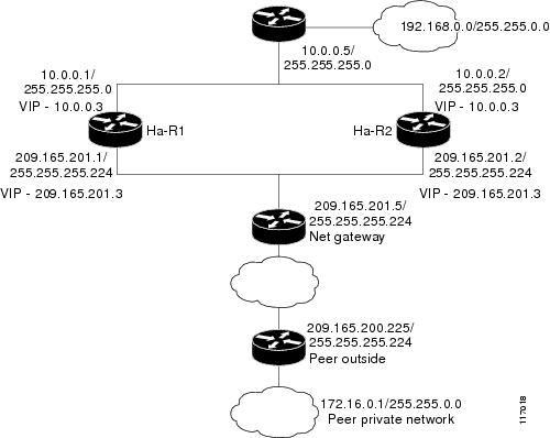
The figure below and the following sample outputs from the show running-config command illustrate how to configure stateful failover on two devices--Ha-R1 and Ha-R2.
Stateful Failover Configuration on Ha-R1
Ha-R1# show running-config
Building configuration...
Current configuration :2086 bytes
!
version 12.3
service timestamps debug datetime msec
service timestamps log datetime msec
no service password-encryption
!
hostname Ha-R1
!
boot-start-marker
boot-end-marker
!
!
redundancy inter-device
scheme standby HA-out
security ipsec sso-secure
!
logging buffered 10000000 debugging
logging rate-limit console 10000
!
!
ipc zone default
association 1
no shutdown
protocol sctp
local-port 5000
local-ip 10.0.0.1
remote-port 5000
remote-ip 10.0.0.2
!
clock timezone PST 0
no aaa new-model
ip subnet-zero
!
crypto isakmp policy 1
encr aes
authentication pre-share
group 14
crypto isakmp key cisco123 address 0.0.0.0 0.0.0.0 no-xauth
!
!
crypto ipsec transform-set trans1 ah-sha-hmac esp-aes
crypto ipsec transform-set trans2 ah-sha-hmac esp-aes 256
!
crypto ipsec profile sso-secure
set transform-set trans2
!
!
crypto map to-peer-outside redundancy replay-interval inbound 1000 outbound 10000
crypto map to-peer-outside 10 ipsec-isakmp
set peer 209.165.200.225
set transform-set trans1
match address peer-outside
!
!
!
interface Ethernet0/0
 ip address 209.165.201.1 255.255.255.224
 standby 1 ip 209.165.201.3
 standby 1 preempt
 standby 1 name HA-out
 standby 1 track Ethernet1/0
 standby delay reload 120
crypto map to-peer-outside redundancy HA-out stateful
!
interface Ethernet1/0
ip address 10.0.0.1 255.255.255.0
standby 2 ip 10.0.0.3
standby 2 preempt
standby 2 name HA-in
standby delay reload 120
standby 2 track Ethernet0/0
!
interface Serial2/0
no ip address
shutdown
serial restart-delay 0
!
interface Serial3/0
no ip address
shutdown
serial restart-delay 0
!
ip classless
ip route 0.0.0.0 0.0.0.0 209.165.201.5
ip route 192.168.0.0 255.255.0.0
no ip http server
no ip http secure-server
!
!
!
ip access-list extended peer-outside
permit ip host 192.168.0.1 host 172.16.0.1
!
!
control-plane
!
!
line con 0
exec-timeout 0 0
transport preferred all
transport output all
line aux 0
transport preferred all
transport output all
line vty 0 4
login
transport preferred all
transport input all
transport output all
!
end
Stateful Failover Configuration on Ha-R2
Ha-R2# show running-config
Building configuration...
Current configuration :2100 bytes
!
version 12.3
service timestamps debug datetime msec
service timestamps log datetime msec
no service password-encryption
!
hostname Ha-R2
!
boot-start-marker
boot-end-marker
!
!
redundancy inter-device
scheme standby HA-out
security ipsec sso-secure
!
logging buffered 10000000 debugging
logging rate-limit console 10000
!
!
ipc zone default
association 1
no shutdown
protocol sctp
local-port 5000
local-ip 10.0.0.2
remote-port 5000
remote-ip 10.0.0.1
!
clock timezone PST 0
no aaa new-model
ip subnet-zero
!
!
crypto isakmp policy 1
encr aes
authentication pre-share
group 14
lifetime 120
crypto isakmp key cisco123 address 0.0.0.0 0.0.0.0 no-xauth
!
!
crypto ipsec transform-set trans1 ah-sha-hmac esp-aes
crypto ipsec transform-set trans2 ah-sha-hmac esp-aes 256
!
crypto ipsec profile sso-secure
set transform-set trans2
!
!
crypto map to-peer-outside redundancy replay-interval inbound 1000 outbound 10000
crypto map to-peer-outside 10 ipsec-isakmp
 set peer 209.165.200.225
 set transform-set trans1
 match address peer-outside
!
!
!
interface Ethernet0/0
ip address 209.165.201.2 255.255.255.224
standby 1 ip 209.165.201.3
standby 1 preempt
standby 1 name HA-out
standby 1 track Ethernet1/0
standby delay reload 120
crypto map to-peer-outside redundancy HA-out stateful
!
interface Ethernet1/0
ip address 10.0.0.2 255.255.255.0
standby 2 ip 10.0.0.3
standby 2 preempt
standby 2 name HA-in
standby delay reload 120
standby 2 track Ethernet0/0
!
interface Serial2/0
no ip address
shutdown
serial restart-delay 0
!
interface Serial3/0
no ip address
shutdown
serial restart-delay 0
!
ip classless
ip route 0.0.0.0 0.0.0.0 209.165.201.5
ip route 192.168.0.0 255.255.0.0
no ip http server
no ip http secure-server
!
!
!
ip access-list extended peer-outside
permit ip host 192.168.0.1 host 172.16.0.1
!
!
control-plane
!
!
line con 0
exec-timeout 0 0
transport preferred all
transport output all
line aux 0
transport preferred all
transport output all
line vty 0 4
login
transport preferred all
transport input all
transport output all
!
end
Example: Configuring Stateful Failover for IPsec for an Easy VPN Server
The following sample outputs from the show running-config command show how to configure stateful failover for a remote access connection via an Easy VPN server:
Stateful Failover for an Easy VPN Server Configuration on RAHA-R1
RAHA-R1# show running-config

Building configuration...
Current configuration :3829 bytes
!
version 12.3
service timestamps debug datetime msec
service timestamps log datetime msec
no service password-encryption
!
hostname RAHA-R1
!
boot-start-marker
boot-end-marker
!
redundancy inter-device
 scheme standby HA-out
!
username remote_user password 0 letmein
!
ipc zone default
 association 1
  no shutdown
  protocol sctp
   local-port 5000
    local-ip 10.0.0.1
   remote-port 5000
    remote-ip 10.0.0.2
!
aaa new-model
!
!
! Enter the following command if you are doing Xauth locally.
aaa authentication login local_xauth local
!
! Enter the following command if you are doing Xauth remotely via RADIUS.
!aaa authentication login radius_xauth group radius
!
! Enter the following command if you are not doing Xauth
!aaa authentication login no_xauth none
!
! Enter the following command if you are doing local group authentication.
aaa authorization network local_auth local
!
! Enter the following command if you are doing group authentication remotely via RADIUS.
!aaa authorization network radius_auth group radius
!
!
! Enter the following command if you are doing Xauth remotely via RADIUS.
!
aaa accounting network radius_accounting start-stop group radius
aaa session-id common
ip subnet-zero
!
crypto isakmp policy 1
 encr aes
 hash sha
 authentication pre-share
 group 14
!
!
! Enter the following command if you are doing group authentication locally.
crypto isakmp client configuration group unity
 key abc123
 domain abc.com
 pool client-address-pool
!
!
crypto ipsec transform-set trans1 esp-aes esp-sha-hmac
!
crypto dynamic-map to-remote-client 10
 set transform-set trans1
 reverse-route remote-peer
!
! Use this map if you want to do local group authentication and Xauth.
crypto map to_peer_outside_local_xauth client authentication list local_xauth
crypto map to_peer_outside_local_xauth isakmp authorization list local_auth
crypto map to_peer_outside_local_xauth client configuration address respond
crypto map to_peer_outside_local_xauth 10 ipsec-isakmp dynamic to-remote-client
!
! Use this map if you want to use Radius for group authentication and Xauth.
!crypto map to_peer_outside_radius_xauth isakmp client authentication list radius_xauth
!crypto map to_peer_outside_radius_xauth client accounting list radius_accounting
!crypto map to_peer_outside_radius_xauth isakmp authorization list radius_auth
!crypto map to_peer_outside_radius_xauth isakmp client configuration address respond
!crypto map to_peer_outside_radius_xauth isakmp 10 ipsec-isakmp dynamic to-remote-client
!
! Use this map if you want to do local group authentication and no Xauth
!crypto map to_peer_outside_no_xauth isakmp authorization list local_auth
!crypto map to_peer_outside_no_xauth configuration address respond
!crypto map to_peer_outside_no_xauth 10 ipsec-isakmp dynamic to-remote-client
!
interface Ethernet0/0
 ip address 209.165.201.1 255.255.255.224
 standby 1 ip 209.165.201.3
 standby 1 preempt
 standby 1 name HA-out
 standby 1 track Ethernet1/0
 standby delay reload 120
 crypto map to_peer_outside_local_xauth redundancy HA-out stateful
!
interface Ethernet1/0
 ip address 10.0.0.1 255.255.255.0
 standby 2 ip 10.0.0.3
 standby 2 preempt
 standby 2 name HA-in
 standby 2 track Ethernet0/0
 standby delay reload 120
!
! Enable loopback0 if you are using radius for Xauth, group auth, or accounting with ! crypto HA
!interface loopback0
! ip address 192.168.100.1 255.255.255.255
!
! Enable this command if you are using radius for Xauth, group auth, or accounting with ! crypto HA
!ip radius source-interface loopback0
!
ip local pool client-address-pool 50.0.0.1 50.0.0.254
ip classless
ip route 0.0.0.0 0.0.0.0 209.165.201.5
ip route 192.168.0.0 255.255.255.0 10.0.0.5
!
radius-server host 192.168.0.0 255.255.0.0 auth-port 1845 acct-port 1846
radius-server key radius123
!
control-plane
!
!
line con 0
 exec-timeout 0 0
line aux 0
line vty 0 4
!
end
Stateful Failover for an Easy VPN Server Configuration on RAHA-R2
RAHA-R2# show running-config

Building configuration...
Current configuration :3829 bytes
!
version 12.3
service timestamps debug datetime msec
service timestamps log datetime msec
no service password-encryption
!
hostname RAHA-R2
!
boot-start-marker
boot-end-marker
!
redundancy inter-device
 scheme standby HA-out
!
username remote_user password 0 letmein
!
ipc zone default
 association 1
  no shutdown
  protocol sctp
   local-port 5000
    local-ip 10.0.0.2
   remote-port 5000
    remote-ip 10.0.0.1
!
aaa new-model
!
!
! Enter the following command if you are doing Xauth locally.
aaa authentication login local_xauth local
!
! Enter the following command if you are doing Xauth remotely via RADIUS.
!aaa authentication login radius_xauth group radius
!
! Enter the following command if you are not doing Xauth.
!aaa authentication login no_xauth none
!
! Enter the following command if you are doing local group authentication.
aaa authorization network local_auth local
!
! Enter the following command if you are doing group authentication remotely via RADIUS.
!aaa authorization network radius_auth group radius
!
!
! Enter the following command if you are doing Xauth remotely via RADIUS.
!aaa accounting network radius_accounting start-stop group radius
aaa session-id common
ip subnet-zero
!
crypto isakmp policy 1
 encr aes
 hash sha
 authentication pre-share
 group 14
!
!
! Enter the following commands if you are doing group authentication locally.
crypto isakmp client configuration group unity
 key abc123
 domain abc.com
 pool client-address-pool
!
!
crypto ipsec transform-set trans1 esp-aes esp-sha-hmac
!
crypto dynamic-map to-remote-client 10
 set transform-set trans1
 reverse-route remote-peer
!
!
! Use this map if you want to dolocal group authentication and Xauth.
crypto map to_peer_outside_local_xauth client authentication list local_xauth
crypto map to_peer_outside_local_xauth isakmp authorization list local_auth
crypto map to_peer_outside_local_xauth client configuration address respond
crypto map to_peer_outside_local_xauth 10 ipsec-isakmp dynamic to-remote-client
!
! Use this map if you want to use Radius for group authentication and Xauth.
!crypto map to_peer_outside_radius_xauth isakmp client authentication list radius_xauth
!crypto map to_peer_outside_radius_xauth client accounting list radius_accounting
!crypto map to_peer_outside_radius_xauth isakmp authorization list radius_auth
!crypto map to_peer_outside_radius_xauth isakmp client configuration address respond
!crypto map to_peer_outside_radius_xauth isakmp 10 ipsec-isakmp dynamic to-remote-client
!
!
! Use this map if you want to do local authentication and no Xauth.
!crypto map to_peer_outside_no_xauth isakmp authorization list local_auth
!crypto map to_peer_outside_no_xauth configuration address respond
!crypto map to_peer_outside_no_xauth 10 ipsec-isakmp dynamic to-remote-client
!
interface Ethernet0/0
 ip address 209.165.201.2 255.255.255.224
 standby 1 ip 209.165.201.3
 standby 1 preempt
 standby 1 name HA-out
 standby 1 track Ethernet1/0
 standby delay reload
 crypto map to_peer_outside_local_xauth redundancy HA-out stateful
!
interface Ethernet1/0
 ip address 10.0.0.2 255.255.255.0
 standby 2 ip 10.0.0.3
 standby 2 preempt
 standby 2 name HA-in
 standby 2 track Ethernet0/0
 standby delay reload
!
! Enable loopback0 if you are using radius for Xauth, group auth, or accounting with ! crypto HA
!interface loopback0
! ip address 192.168.100.1 255.255.255.255
!
! Enable this command if you are using radius for Xauth, group auth, or accounting with ! crypto HA
!ip radius source-interface loopback0
!
ip local pool client-address-pool 50.0.0.1 50.0.0.254
ip classless
ip route 0.0.0.0 0.0.0.0 209.165.201.5
ip route 192.168.0.0 255.255.0.0
!
radius-server host 192.168.0.200 auth-port 1845 acct-port 1846
radius-server key radius123
!
control-plane
!
!
!
line con 0
 exec-timeout 0 0
line aux 0
line vty 0 4
!
end
Additional References
Related Documents
|
Related Topic |
Document Title |
|---|---|
|
Cisco IOS commands |
|
|
Security commands |
|
|
RRI |
"IPSec VPN High Availability Enhancements" in the VPN Availability Configuration Guide |
|
HSRP |
"Configuring HSRP" in the First Hop Redundancy Protocols Configuration Guide |
|
Easy VPN Server |
"Cisco Easy VPN Remote" in the Easy VPN Configuration Guide |
|
IKE configuration |
"Configuring Internet Key Exchange for IPsec VPNs" in the Internet Key Exchange for IPsec VPNs Configuration Guide |
|
IPsec configuration |
"Configuring Security for VPNs with IPsec" in the Security for VPNs with IPsec Configuration Guide |
|
Recommended cryptographic algorithms |
Technical Assistance
|
Description |
Link |
|---|---|
|
The Cisco Support and Documentation website provides online resources to download documentation, software, and tools. Use these resources to install and configure the software and to troubleshoot and resolve technical issues with Cisco products and technologies. Access to most tools on the Cisco Support and Documentation website requires a Cisco.com user ID and password. |
Feature Information for Stateful Failover for IPsec
The following table provides release information about the feature or features described in this module. This table lists only the software release that introduced support for a given feature in a given software release train. Unless noted otherwise, subsequent releases of that software release train also support that feature.
Use Cisco Feature Navigator to find information about platform support and Cisco software image support. To access Cisco Feature Navigator, go to www.cisco.com/go/cfn. An account on Cisco.com is not required.
| Table 2 | Feature Information for Stateful Failover for IPsec |
|
Feature Name |
Releases |
Feature Information |
|---|---|---|
|
Stateful Failover for IPsec |
12.3(11)T |
The Stateful Failover for IP Sec feature enables a router to continue processing and forwarding IPsec packets after a planned or unplanned outage occurs. Customers employ a backup (secondary) router that automatically takes over the tasks of the active (primary) router if the active router loses connectivity for any reason. The following commands were introduced or modified: clear crypto isakmp , clear crypto sa , clear crypto session , crypto map (interface IPsec) , crypto map redundancy replay-interval , debug crypto ha , debug crypto ipsec ha , debug crypto isakmp ha , local-ip (IPC transport-SCTP local) , local-port , redundancy inter-device , redundancy stateful , remote-ip (IPC transport-SCTP remote) , remote-port , scheme , security ipsec , show crypto ha , show crypto ipsec sa , show crypto isakmp sa , show crypto session , show redundancy . |
Cisco and the Cisco logo are trademarks or registered trademarks of Cisco and/or its affiliates in the U.S. and other countries. To view a list of Cisco trademarks, go to this URL: www.cisco.com/go/trademarks. Third-party trademarks mentioned are the property of their respective owners. The use of the word partner does not imply a partnership relationship between Cisco and any other company. (1110R)
Any Internet Protocol (IP) addresses and phone numbers used in this document are not intended to be actual addresses and phone numbers. Any examples, command display output, network topology diagrams, and other figures included in the document are shown for illustrative purposes only. Any use of actual IP addresses or phone numbers in illustrative content is unintentional and coincidental.