
 Feedback
Contents
- Dynamic Multipoint VPN
- Finding Feature Information
- Prerequisites for Dynamic Multipoint VPN (DMVPN)
- Restrictions for Dynamic Multipoint VPN (DMVPN)
- DMVPN Support on the Cisco 6500 and Cisco 7600
- Information About Dynamic Multipoint VPN (DMVPN)
- Benefits of Dynamic Multipoint VPN (DMVPN)
- Feature Design of Dynamic Multipoint VPN (DMVPN)
- IPsec Profiles
- VRF Integrated DMVPN
- DMVPN--Enabling Traffic Segmentation Within DMVPN
- NAT-Transparency Aware DMVPN
- Call Admission Control with DMVPN
- NHRP Rate-Limiting Mechanism
- How to Configure Dynamic Multipoint VPN (DMVPN)
- Configuring an IPsec Profile
- What to Do Next
- Configuring the Hub for DMVPN
- Configuring the Spoke for DMVPN
- Configuring the Forwarding of Clear-Text Data IP Packets into a VRF
- Configuring the Forwarding of Encrypted Tunnel Packets into a VRF
- Configuring DMVPN--Traffic Segmentation Within DMVPN
- Prerequisites
- Enabling MPLS on the VPN Tunnel
- Configuring Multiprotocol BGP on the Hub Router
- Configuring Multiprotocol BGP on the Spoke Routers
- Troubleshooting Dynamic Multipoint VPN (DMVPN)
- What to Do Next
- Configuration Examples for Dynamic Multipoint VPN (DMVPN) Feature
- Example Hub Configuration for DMVPN
- Example Spoke Configuration for DMVPN
- Example VRF Aware DMVPN
- Example 2547oDMVPN with Traffic Segmentation (with BGP only)
- Example 2547oDMVPN with Traffic Segmentation (Enterprise Branch)
- Additional References
- Feature Information for Dynamic Multipoint VPN (DMVPN)
- Glossary
Dynamic Multipoint VPN
The Dynamic Multipoint VPN (DMVPN) feature allows users to better scale large and small IP Security (IPsec) Virtual Private Networks (VPNs) by combining generic routing encapsulation (GRE) tunnels, IPsec encryption, and Next Hop Resolution Protocol (NHRP).
 Note | Security threats, as well as the cryptographic technologies to help protect against them, are constantly changing. For more information about the latest Cisco cryptographic recommendations, see the Next Generation Encryption (NGE) white paper. |
- Finding Feature Information
- Prerequisites for Dynamic Multipoint VPN (DMVPN)
- Restrictions for Dynamic Multipoint VPN (DMVPN)
- Information About Dynamic Multipoint VPN (DMVPN)
- How to Configure Dynamic Multipoint VPN (DMVPN)
- Configuration Examples for Dynamic Multipoint VPN (DMVPN) Feature
- Additional References
- Feature Information for Dynamic Multipoint VPN (DMVPN)
- Glossary
Finding Feature Information
Your software release may not support all the features documented in this module. For the latest caveats and feature information, see Bug Search Tool and the release notes for your platform and software release. To find information about the features documented in this module, and to see a list of the releases in which each feature is supported, see the feature information table at the end of this module.
Use Cisco Feature Navigator to find information about platform support and Cisco software image support. To access Cisco Feature Navigator, go to www.cisco.com/go/cfn. An account on Cisco.com is not required.
Prerequisites for Dynamic Multipoint VPN (DMVPN)
- Before a multipoint GRE (mGRE) and IPsec tunnel can be established, you must define an Internet Key Exchange (IKE) policy by using the crypto isakmp policy command.
- For the NAT-Transparency Aware enhancement to work, you must use IPsec transport mode on the transform set. Also, even though NAT-Transparency can support two peers (IKE and IPsec) being translated to the same IP address (using the User Datagram Protocol [UDP] ports to differentiate them [that is, Peer Address Translation (PAT)]), this functionality is not supported for DMVPN. All DMVPN spokes must have a unique IP address after they have been NAT translated. They can have the same IP address before they are NAT translated.
- To enable 2547oDMPVN--Traffic Segmentation Within DMVPN you must configure multiprotocol label switching (MPLS) by using the mpls ip command.
Restrictions for Dynamic Multipoint VPN (DMVPN)
- If you use the Dynamic Creation for Spoke-to-Spoke Tunnels benefit of this feature, you must use IKE certificates or wildcard preshared keys for Internet Security Association Key Management Protocol (ISAKMP) authentication.
Note | It is highly recommended that you do not use wildcard preshared keys because the attacker will have access to the VPN if one spoke router is compromised. |
- GRE tunnel keepalives (that is, the keepalive command under a GRE interface) are not supported on point-to-point or multipoint GRE tunnels in a DMVPN Network.
- For best DMVPN functionality, it is recommended that you run the latest Cisco IOS software Release 12.4 mainline,12.4T, or 12.2(18)SXF.
- If one spoke is behind one NAT device and another different spoke is behind another NAT device, and Peer Address Translation (PAT) is the type of NAT used on both NAT devices, then a session initiated between the two spokes cannot be established.
One example of a PAT configuration on a NAT interface is:
ip nat inside source list nat_acl interface FastEthernet0/1 overload
DMVPN Support on the Cisco 6500 and Cisco 7600
Blade-to-Blade Switchover on the Cisco 6500 and Cisco 7600
- DMVPN does not support blade-to-blade switchover on the Cisco 6500 and Cisco 7600.
Cisco 6500 or Cisco 7600 As a DMVPN Hub
- A Cisco 6500 or Cisco 7600 that is functioning as a DMVPN hub cannot be located behind a NAT router.
- If a Cisco 6500 or Cisco 7600 is functioning as a DMVPN hub, the spoke behind NAT must be a Cisco 6500 or Cisco 7600, respectively, or the router must be upgraded to Cisco IOS software Release 12.3(11)T02 or a later release.
Cisco 6500 or Cisco 7600 As a DMVPN Spoke
- If a Cisco 6500 or Cisco 7600 is functioning as a spoke, the hub cannot be behind NAT.
- If a Cisco 6500 or Cisco 7600 is functioning as a DMVPN spoke behind NAT, the hub must be a Cisco 6500 or Cisco 7600, respectively, or the router must be upgraded to Cisco IOS Release 12.3(11)T02 or a later release.
DMVPN Hub or Spoke Supervisor Engine
- Only a Supervisor Engine 720 can be used as a DMVPN hub or spoke. A Supervisor Engine 2 cannot be used.
Encrypted Multicast with GRE
- Encrypted Multicast with GRE is not supported on the Cisco 6500 nor on the Cisco 7600.
mGRE Interfaces
- If there are two mGRE interfaces on the same DMVPN node and they both do not have a tunnel key, the two mGRE interfaces must each have a unique tunnel source address (or interface) configured.
- On the Cisco 6500 and Cisco 7600, each GRE interface (multipoint or point-to-point) must have a unique tunnel source address (or interface).
- The following commands are not supported under mGRE with DMVPN: ip tcp adjust-mss, qos pre-classify tunnel vrf, tunnel path-mtu-discovery, and tunnel vrf.
Tunnel Key
- The use of a tunnel key on a GRE (multipoint or point-to-point) interface is not supported in the hardware switching ASICs on the Cisco 6500 and Cisco 7600 platforms. If a tunnel key is configured, throughput performance is greatly reduced.
- In Cisco IOS Release 12.3(11)T3 and Release 12.3(14)T, the requirement that a mGRE interface must have a tunnel key was removed. Therefore, in a DMVPN network that includes a Cisco 6500 or Cisco 7600 as a DMVPN node, you should remove the tunnel key from all DMVPN nodes in the DMVPN network, thus preserving the throughput performance on the Cisco 6500 and Cisco 7600 platforms.
- If the tunnel key is not configured on any DMVPN node within a DMVPN network, it must not be configured on all DMVPN nodes with the DMVPN network.
VRF-Aware DMVPN Scenarios
- The mls mpls tunnel-recircommand must be configured on the provider equipment (PE) DMVPN hub if customer equipment (CE) DMVPN spokes need to "talk" to other CEs across the MPLS cloud.
- The mGRE interface should be configured with a large enough IP maximum transmission unit (1400 packets to avoid having the route processor doing fragmentation.
- Enhanced Interior Gateway Routing Protocol (EIGRP) should be avoided.
Information About Dynamic Multipoint VPN (DMVPN)
- Benefits of Dynamic Multipoint VPN (DMVPN)
- Feature Design of Dynamic Multipoint VPN (DMVPN)
- IPsec Profiles
- VRF Integrated DMVPN
- DMVPN--Enabling Traffic Segmentation Within DMVPN
- NAT-Transparency Aware DMVPN
- Call Admission Control with DMVPN
- NHRP Rate-Limiting Mechanism
Benefits of Dynamic Multipoint VPN (DMVPN)
Hub Router Configuration Reduction
- Currently, for each spoke router, there is a separate block of configuration lines on the hub router that define the crypto map characteristics, the crypto access list, and the GRE tunnel interface. This feature allows users to configure a single mGRE tunnel interface, a single IPsec profile, and no crypto access lists on the hub router to handle all spoke routers. Thus, the size of the configuration on the hub router remains constant even if spoke routers are added to the network.
- DMVPN architecture can group many spokes into a single multipoint GRE interface, removing the need for a distinct physical or logical interface for each spoke in a native IPsec installation.
Automatic IPsec Encryption Initiation
- GRE has the peer source and destination address configured or resolved with NHRP. Thus, this feature allows IPsec to be immediately triggered for the point-to-point GRE tunneling or when the GRE peer address is resolved via NHRP for the multipoint GRE tunnel.
Support for Dynamically Addressed Spoke Routers
- When using point-to-point GRE and IPsec hub-and-spoke VPN networks, the physical interface IP address of the spoke routers must be known when configuring the hub router because IP address must be configured as the GRE tunnel destination address. This feature allows spoke routers to have dynamic physical interface IP addresses (common for cable and DSL connections). When the spoke router comes online, it will send registration packets to the hub router: within these registration packets, is the current physical interface IP address of this spoke.
Dynamic Creation for Spoke-to-Spoke Tunnels
- This feature eliminates the need for spoke-to-spoke configuration for direct tunnels. When a spoke router wants to transmit a packet to another spoke router, it can now use NHRP to dynamically determine the required destination address of the target spoke router. (The hub router acts as the NHRP server, handling the request for the source spoke router.) The two spoke routers dynamically create an IPsec tunnel between them so data can be directly transferred.
VRF Integrated DMVPN
- DMVPNs can be used to extend the Multiprotocol Label Switching (MPLS) networks that are deployed by service providers to take advantage of the ease of configuration of hub and spokes, to provide support for dynamically addressed customer premises equipment (CPEs), and to provide zero-touch provisioning for adding new spokes into a DMVPN.
Feature Design of Dynamic Multipoint VPN (DMVPN)
The Dynamic Multipoint VPN (DMVPN) feature combines GRE tunnels, IPsec encryption, and NHRP routing to provide users an ease of configuration via crypto profiles--which override the requirement for defining static crypto maps--and dynamic discovery of tunnel endpoints.
This feature relies on the following two Cisco enhanced standard technologies:
- NHRP--A client and server protocol where the hub is the server and the spokes are the clients. The hub maintains an NHRP database of the public interface addresses of the each spoke. Each spoke registers its real address when it boots and queries the NHRP database for real addresses of the destination spokes to build direct tunnels.
- mGRE Tunnel Interface --Allows a single GRE interface to support multiple IPsec tunnels and simplifies the size and complexity of the configuration.
The topology shown in the diagram below and the corresponding bullets explain how this feature works.
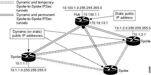
- Each spoke has a permanent IPsec tunnel to the hub, not to the other spokes within the network. Each spoke registers as clients of the NHRP server.
- When a spoke needs to send a packet to a destination (private) subnet on another spoke, it queries the NHRP server for the real (outside) address of the destination (target) spoke.
- After the originating spoke "learns" the peer address of the target spoke, it can initiate a dynamic IPsec tunnel to the target spoke.
- The spoke-to-spoke tunnel is built over the multipoint GRE interface.
- The spoke-to-spoke links are established on demand whenever there is traffic between the spokes. Thereafter, packets can bypass the hub and use the spoke-to-spoke tunnel.
Note | After a preconfigured amount of inactivity on the spoke-to-spoke tunnels, the router will tear down those tunnels to save resources (IPsec security associations [SAs]). |
IPsec Profiles
IPsec profiles abstract IPsec policy information into a single configuration entity, which can be referenced by name from other parts of the configuration. Therefore, users can configure functionality such as GRE tunnel protection with a single line of configuration. By referencing an IPsec profile, the user does not have to configure an entire crypto map configuration. An IPsec profile contains only IPsec information; that is, it does not contain any access list information or peering information.
VRF Integrated DMVPN
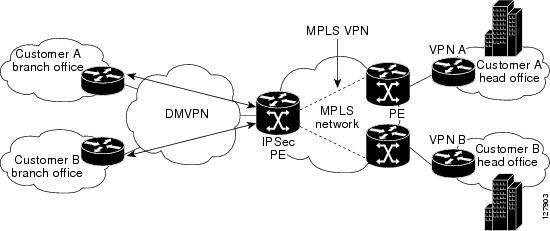
VPN Routing and Forwarding (VRF) Integrated DMVPN enables users to map DMVPN multipoint interfaces into MPLS VPNs. This mapping allows Internet service providers (ISPs) to extend their existing MPLS VPN services by mapping off-network sites (typically a branch office) to their respective MPLS VPNs. Customer equipment (CE) routers are terminated on the DMVPN PE router, and traffic is placed in the VRF instance of an MPLS VPN.
DMVPN can interact with MPLS VPNs in two ways:
- The ip vrf forwarding command is used to inject the data IP packets (those packets inside the mGRE+IPsec tunnel) into the MPLS VPN. The ip vrf forwarding command is supported for DMVPN in Cisco IOS Release 12.3(6) and Release 12.3(7)T.
- The tunnel vrf command is used to transport (route) the mGRE+IPsec tunnel packet itself within an MPLS VPN. The tunnel vrf command is supported in Cisco IOS Release 12.3(11)T but not in Cisco IOS Release 12.2(18)SXE.
Note | Clear-text data IP packets are forwarded in a VRF using the ip vrf forwarding command, and encrypted tunnel IP packets are forwarded in a VRF using the tunnel vrf command. |
The ip vrf forwarding and tunnel vrf commands may be used at the same time. If they are used at the same time, the VRF name of each command may be the same or different.
For information about configuring the forwarding of clear-text data IP packets into a VRF, see the section "Configuring the Forwarding of Clear-Text Data IP Packets into a VRF." For information about configuring the forwarding of encrypted tunnel packets into a VRF, see the section "Configuring the Forwarding of Encrypted Tunnel Packets into a VRF."
For more information about configuring VRF, see reference in the "Related Documents" section.
The diagram below illustrates a typical VRF Integrated DMVPN scenario.
DMVPN--Enabling Traffic Segmentation Within DMVPN
Cisco IOS Release 12.4(11)T provides an enhancement that allows you to segment VPN traffic within a DMVPN tunnel. VRF instances are labeled, using MPLS, to indicate their source and destination.
The diagram below and the corresponding bullets explain how traffic segmentation within DMVPN works.
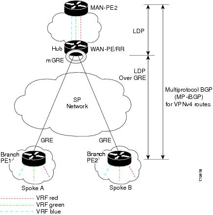
- The hub shown in the diagram is a WAN-PE and a route reflector, and the spokes (PE routers) are clients.
- There are three VRFs, designated "red," "green," and "blue."
- Each spoke has both a neighbor relationship with the hub (multiprotocol Border Gateway Protocol [MP-iBGP] peering) and a GRE tunnel to the hub.
- Each spoke advertises its routes and VPNv4 prefixes to the hub.
- The hub sets its own IP address as the next-hop route for all the VPNv4 addresses it learns from the spokes and assigns a local MPLS label for each VPN when it advertises routes back to the spokes. As a result, traffic from Spoke A to Spoke B is routed via the hub.
An example illustrates the process:
- Spoke A advertises a VPNv4 route to the hub, and applies the label X to the VPN.
- The hub changes the label to Y when the hub advertises the route to Spoke B.
- When Spoke B has traffic to send to Spoke A, it applies the Y label, and the traffic goes to the hub.
- The hub swaps the VPN label, by removing the Y label and applying an X label, and sends the traffic to Spoke A.
NAT-Transparency Aware DMVPN
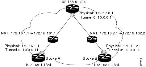
DMVPN spokes are often situated behind a NAT router (which is often controlled by the ISP for the spoke site) with the outside interface address of the spoke router being dynamically assigned by the ISP using a private IP address (per Internet Engineering Task Force [IETF] RFC 1918).
Prior to Cisco IOS Release 12.3(6) and 12.3(7)T, these spoke routers had to use IPsec tunnel mode to participate in a DMVPN network. In addition, their assigned outside interface private IP address had to be unique across the DMVPN network. Even though ISAKMP and IPsec would negotiate NAT-T and "learn" the correct NAT public address for the private IP address of this spoke, NHRP could only "see" and use the private IP address of the spoke for its mapping entries. Effective with the NAT-Transparency Aware DMVPN enhancement, NHRP can now learn and use the NAT public address for its mappings as long as IPsec transport mode is used (which is the recommend IPsec mode for DMVPN networks). The restriction that the private interface IP address of the spoke must be unique across the DMVPN network has been removed. It is recommended that all DMVPN routers be upgraded to the new code before you try to use the new functionality even though spoke routers that are not behind NAT do not need to be upgraded. In addition, you cannot convert upgraded spoke routers that are behind NAT to the new configuration (IPsec transport mode) until the hub routers have been upgraded.
Also added in Cisco IOS Releases 12.3(9a) and 12.3(11)T is the capability to have the hub DMVPN router behind static NAT. This was a change in the ISAKMP NAT-T support. For this functionality to be used, all the DMVPN spoke routers and hub routers must be upgraded, and IPsec must use transport mode.
For these NAT-Transparency Aware enhancements to work, you must use IPsec transport mode on the transform set. Also, even though NAT-Transparency (IKE and IPsec) can support two peers (IKE and IPsec) being translated to the same IP address (using the UDP ports to differentiate them), this functionality is not supported for DMVPN. All DMVPN spokes must have a unique IP address after they have been NAT translated. They can have the same IP address before they are NAT translated.
The diagram below illustrates a NAT-Transparency Aware DMVPN scenario.
Call Admission Control with DMVPN
In a DMVPN network, it is easy for a DMVPN router to become "overwhelmed" with the number of tunnels it is trying to build. Call Admission Control can be used to limit the number of tunnels that can be built at any one time, thus protecting the memory of the router and CPU resources.
It is most likely that Call Admission Control will be used on a DMVPN spoke to limit the total number of ISAKMP sessions (DMVPN tunnels) that a spoke router will attempt to initiate or accept. This limiting is accomplished by configuring an IKE SA limit under Call Admission Control, which configures the router to drop new ISAKMP session requests (inbound and outbound) if the current number of ISAKMP SAs exceeds the limit.
It is most likely that Call Admission Control will be used on a DMVPN hub to rate limit the number of DMVPN tunnels that are attempting to be built at the same time. The rate limiting is accomplished by configuring a system resource limit under Call Admission Control, which configures the router to drop new ISAKMP session requests (new DMVPN tunnels) when the system utilization is above a specified percentage. The dropped session requests allow the DMVPN hub router to complete the current ISAKMP session requests, and when the system utilization drops, it can process the previously dropped sessions when they are reattempted.
No special configuration is required to use Call Admission Control with DMVPN. For information about configuring Call Admission Control, see the reference in the section "Related Documents."
NHRP Rate-Limiting Mechanism
NHRP has a rate-limiting mechanism that restricts the total number of NHRP packets from any given interface. The default values, which are set using the ip nhrp max-send command, are 100 packets every 10 seconds per interface. If the limit is exceeded, you will get the following system message:
%NHRP-4-QUOTA: Max-send quota of [int]pkts/[int]Sec. exceeded on [chars]
For more information about this system message, see the document 12.4T System Message Guide.
How to Configure Dynamic Multipoint VPN (DMVPN)
To enable mGRE and IPsec tunneling for hub and spoke routers, you must configure an IPsec profile that uses a global IPsec policy template and configure your mGRE tunnel for IPsec encryption. This section contains the following procedures:
- Configuring an IPsec Profile
- Configuring the Hub for DMVPN
- Configuring the Spoke for DMVPN
- Configuring the Forwarding of Clear-Text Data IP Packets into a VRF
- Configuring the Forwarding of Encrypted Tunnel Packets into a VRF
- Configuring DMVPN--Traffic Segmentation Within DMVPN
- Troubleshooting Dynamic Multipoint VPN (DMVPN)
Configuring an IPsec Profile
The IPsec profile shares most of the same commands with the crypto map configuration, but only a subset of the commands are valid in an IPsec profile. Only commands that pertain to an IPsec policy can be issued under an IPsec profile; you cannot specify the IPsec peer address or the access control list (ACL) to match the packets that are to be encrypted.
Note | Security threats, as well as the cryptographic technologies to help protect against them, are constantly changing. For more information about the latest Cisco cryptographic recommendations, see the Next Generation Encryption (NGE) white paper. |
Before configuring an IPsec profile, you must define a transform set by using the crypto ipsec transform-set command.
DETAILED STEPS
Configuring the Hub for DMVPN
To configure the hub router for mGRE and IPsec integration (that is, associate the tunnel with the IPsec profile configured in the previous procedure), use the following commands:
DETAILED STEPS
Configuring the Spoke for DMVPN
To configure spoke routers for mGRE and IPsec integration, use the following commands.
Note | NHRP network IDs are locally significant and can be different. It makes sense from a deployment and maintenance perspective to use unique network IDnumbers (using the ip nhrp network-id command) across all routers in a DMVPN network, but it is not necessary that they be the same. |
DETAILED STEPS
| Command or Action | Purpose | |||
|---|---|---|---|---|
Step 1 |
enable
Example: Router> enable |
Enables higher privilege levels, such as privileged EXEC mode. Enter your password if prompted. | ||
Step 2 |
configure
terminal
Example: Router# configure terminal |
Enters global configuration mode. | ||
Step 3 |
interface
tunnel
number
Example: Router(config)# interface tunnel 5 |
Configures a tunnel interface and enters interface configuration mode. | ||
Step 4 |
ip
address
ip-address
mask
secondary
Example: Router(config-if)# ip address 10.0.0.2 255.255.255.0 |
Sets a primary or secondary IP address for the tunnel interface.
| ||
Step 5 |
ip
mtu
bytes
Example: Router(config-if)# ip mtu 1400 |
Sets the MTU size, in bytes, of IP packets sent on an interface. | ||
Step 6 |
ip
nhrp
authentication
string
Example: Router(config-if)# ip nhrp authentication donttell |
Configures the authentication string for an interface using NHRP.
| ||
Step 7 | ip nhrp map
hub-tunnel-ip-address
hub-physical-ip-address
Example: Router(config-if)# ip nhrp map 10.0.0.1 172.17.0.1 |
Statically configures the IP-to-NBMA address mapping of IP destinations connected to an MBMA network. | ||
Step 8 |
ip
nhrp
map
multicast
hub-physical-ip-address
Example: Router(config-if)# ip nhrp map multicast 172.17.0.1 |
Enables the use of a dynamic routing protocol between the spoke and hub, and sends multicast packets to the hub router. | ||
Step 9 |
ip
nhrp
nhs
hub-tunnel-ip-address
Example: Router(config-if)# ip nhrp nhs 10.0.0.1 |
Configures the hub router as the NHRP next-hop server. | ||
Step 10 |
ip
nhrp
network-id
number
Example: Router(config-if)# ip nhrp network-id 99 |
Enables NHRP on an interface. | ||
Step 11 |
tunnel
source
{ip-address |
type
number}
Example: Router (config-if)# tunnel source Ethernet0 |
Sets the source address for a tunnel interface. | ||
Step 12 |
tunnel
key
key-number
Example: Router (config-if)# tunnel key 100000 |
(Optional) Enables an ID key for a tunnel interface.
| ||
Step 13 |
Sets the encapsulation mode to mGRE for the tunnel interface. Use this command if data traffic can use dynamic spoke-to-spoke traffic. Specifies the destination for a tunnel interface. Use this command if data traffic can use hub-and-spoke tunnels. | |||
Step 14 |
tunnel
protection
ipsec
profile
name
Example: Router(config-if)# tunnel protection ipsec profile vpnprof |
Associates a tunnel interface with an IPsec profile. | ||
Step 15 |
bandwidth
kbps
Example: Router(config-if)# bandwidth 1000 |
Sets the current bandwidth value for an interface to higher-level protocols.
The bandwidth setting for the spoke does not need to equal the bandwidth setting for the DMVPN hub. It is usually easier if all of the spokes use the same or similar value. | ||
Step 16 |
ip
tcp
adjust-mss
max-segment-size
Example: Router(config-if)# ip tcp adjust-mss 1360 |
Adjusts the maximum segment size (MSS) value of TCP packets going through a router.
The recommended number value is 1360 when the number of IP MTU bytes is set to 1400. With these recommended settings, TCP sessions quickly scale back to 1400-byte IP packets so the packets will "fit" in the tunnel. | ||
Step 17 |
ip
nhrp
holdtime
seconds
Example: Router(config-if)# ip nhrp holdtime 450 |
Changes the number of seconds that NHRP NBMA addresses are advertised as valid in authoritative NHRP responses. | ||
Step 18 |
delay
number
Example: Router(config-if)# delay 1000 |
(Optional) Used to change the EIGRP routing metric for routes learned over the tunnel interface. |
Configuring the Forwarding of Clear-Text Data IP Packets into a VRF
To configure the forwarding of clear-text date IP packets into a VRF, perform the following steps. This configuration assumes that the VRF BLUE has already been configured.
DETAILED STEPS
| Command or Action | Purpose | |
|---|---|---|
Step 1 |
enable
Example: Router> enable |
Enables higher privilege levels, such as privileged EXEC mode. Enter your password if prompted. |
Step 2 |
configure terminal Example: Router# configure terminal |
Enters global configuration mode. |
Step 3 |
interface type number Example: Router (config)# interface tunnel0 |
Configures an interface type and enters interface configuration mode. |
Step 4 |
ip
vrf
forwarding
vrf-name
Example: Router (config-if)# ip vrf forwarding BLUE |
Associates a VPN VRF with an interface or subinterface. |
Configuring the Forwarding of Encrypted Tunnel Packets into a VRF
To configure the forwarding of encrypted tunnel packets into a VRF, perform the following steps. This configuration assumes that the VRF RED has already been configured.
DETAILED STEPS
| Command or Action | Purpose | |
|---|---|---|
Step 1 |
enable
Example: Router> enable |
Enables higher privilege levels, such as privileged EXEC mode. Enter your password if prompted. |
Step 2 |
configure terminal Example: Router# configure terminal |
Enters global configuration mode. |
Step 3 |
interface type number Example: Router (config)# interface tunnel0 |
Configures an interface type and enters interface configuration mode. |
Step 4 |
tunnel
vrf
vrf-name
Example: Router (config-if)# tunnel vrf RED |
Associates a VPN VRF instance with a specific tunnel destination, interface, or subinterface. |
Configuring DMVPN--Traffic Segmentation Within DMVPN
There are no new commands to use for configuring traffic segmentation, but there are tasks you must complete in order to segment traffic within a DMVPN tunnel:
- Prerequisites
- Enabling MPLS on the VPN Tunnel
- Configuring Multiprotocol BGP on the Hub Router
- Configuring Multiprotocol BGP on the Spoke Routers
Prerequisites
The tasks that follow assume that the DMVPN tunnel and the VRFs "red" and "blue" have already been configured.
For information on configuring a DMVPN tunnel, see the Configuring the Hub for DMVPN task and the Configuring the Spoke for DMVPN. For details about VRF configuration, see the Configuring the Forwarding of Clear-Text Data IP Packets into a VRF task and the Configuring the Forwarding of Encrypted Tunnel Packets into a VRF task.
Enabling MPLS on the VPN Tunnel
Because traffic segmentation within a DMVPN tunnel depends upon MPLS, you must configure MPLS for each VRF instance in which traffic will be segmented. For detailed information about configuring MPLS, see Cisco IOS Multiprotocol Label Switching Configuration Guide, Release 12.4.
DETAILED STEPS
| Command or Action | Purpose | |
|---|---|---|
Step 1 |
enable
Example: Router> enable |
Enables higher privilege levels, such as privileged EXEC mode. Enter your password if prompted. |
Step 2 | configure terminal
Example: Router# configure terminal |
Enters global configuration mode. |
Step 3 | interface
type
number
Example: Router (config)# interface tunnel0 |
Configures an interface type and enters interface configuration mode. |
Step 4 |
mpls
ip
Example: Router (config-if)# mpls ip |
Enables MPLS tagging of packets on the specified tunnel interface. |
Configuring Multiprotocol BGP on the Hub Router
You must configure multiprotocol iBGP (MP-iBGP) to enable advertisement of VPNv4 prefixes and labels to be applied to the VPN traffic. Use BGP to configure the hub as a route reflector. To force all traffic to be routed via the hub, configure the BGP route reflector to change the next hop to itself when it advertises VPNv4 prefixes to the route reflector clients (spokes).
DETAILED STEPS
| Command or Action | Purpose | |
|---|---|---|
Step 1 |
enable
Example: Router> enable |
Enables higher privilege levels, such as privileged EXEC mode.
|
Step 2 | configure terminal
Example: Router# configure terminal |
Enters global configuration mode. |
Step 3 |
router
bgp
Example: Router (config)# router bgp |
Enters BGP configuration mode. |
Step 4 |
neighbor
ipaddress
remote-as
as
-
number
Example: Router (config)# neighbor 10.0.0.11 remote-as 1 |
Adds an entry to the BGP or multiprotocol BGP neighbor table. |
Step 5 |
neighbor
ipaddress
update-source
interface
Example: Router (config)# neighbor 10.10.10.11 update-source Tunnel1 |
Configures the Cisco IOS software to allow BGP sessions to use any operational interface for TCP connections. |
Step 6 |
address-family
vpnv4
Example: Router (config)# address-family vpnv4 |
Enters address family configuration mode to configure a routing session using Virtual Private Network (VPN) Version 4 address prefixes. |
Step 7 |
neighbor
ipaddress
activate
Example: Router (config)# neighbor 10.0.0.11 activate |
Enables the exchange of information with a BGP neighbor. |
Step 8 |
neighbor
ipaddress
send-community
extended
Example: Router (config)# neighbor 10.0.0.11 send-community extended |
Specifies that extended community attributes should be sent to a BGP neighbor. |
Step 9 |
neighbor
ipaddress
route-reflector-client
Example: Router (config)# neighbor 10.0.0.11 route-reflector-client |
Configures the router as a BGP route reflector and configures the specified neighbor as its client. |
Step 10 |
neighbor
ipaddress
route-map
nexthop
out
Example: Router (config)# neighbor 10.0.0.11 route-map nexthop out |
Forces all traffic to be routed via the hub. |
Step 11 |
exit-address-family
Example: Router (config)# exit-address-family |
Exits the address family configuration mode for VPNv4. |
Step 12 |
address-family
ipv4
vrf-name
Example: Router (config)# address-family ipv4 vrf red |
Enters address family configuration mode to configure a routing session using standard IP Version 4 address prefixes. |
Step 13 |
redistribute
connected
Example: Router (config)# redistribute connected |
Redistributes routes that are established automatically by virtue of having enabled IP on an interface from one routing domain into another routing domain. |
Step 14 |
route-map
Example: Router (config)# route-map nexthop permit 10 |
Enters route map configuration mode to configure the next-hop that will be advertised to the spokes. |
Step 15 |
set
ip
next-hop
ipaddress
Example: Router (config)# set ip next-hop 10.0.0.1 |
Sets the next hop to be the hub. |
Configuring Multiprotocol BGP on the Spoke Routers
Multiprotocol-iBGP (MP-iBGP) must be configured on the spoke routers and the hub. Follow the steps below for each spoke router in the DMVPN.
DETAILED STEPS
| Command or Action | Purpose | |||
|---|---|---|---|---|
Step 1 |
enable
Example: Router> enable |
Enables higher privilege levels, such as privileged EXEC mode.
| ||
Step 2 |
configure terminal Example: Router# configure terminal |
Enters global configuration mode. | ||
Step 3 |
router
bgp
Example: Router (config)# router bgp 1 |
Enters BGP configuration mode. | ||
Step 4 |
neighbor
ipaddress
remote-as
as
-
number
Example: Router (config)# neighbor 10.0.0.1 remote-as 1 |
Adds an entry to the BGP or multiprotocol BGP neighbor table. | ||
Step 5 |
neighbor
ipaddress
update-source
interface
Example: Router (config)# neighbor 10.10.10.1 update-source Tunnel1 |
Configures the Cisco IOS software to allow BGP sessions to use any operational interface for TCP connections. | ||
Step 6 |
address-family
vpnv4
Example: Router (config)# address-family vpnv4 |
Enters address family configuration mode to configure a routing session using Virtual Private Network (VPN) Version 4 address prefixes. | ||
Step 7 |
neighbor
ipaddress
activate
Example: Router (config)# neighbor 10.0.0.1 activate |
Enables the exchange of information with a BGP neighbor. | ||
Step 8 |
neighbor
ipaddress
send-community
extended
Example: Router (config)# neighbor 10.0.0.1 send-community extended |
Specifies that extended community attributes should be sent to a BGP neighbor. | ||
Step 9 |
exit-address-family
Example: Router (config)# exit-address-family |
Exits the address family configuration mode. | ||
Step 10 |
address-family
ipv4
vrf-name
Example: Router (config)# address-family ipv4 vrf red |
Enters address family configuration mode to configure a routing session using standard IP Version 4 address prefixes. | ||
Step 11 |
redistribute
connected
Example: Router (config)# redistribute connected |
Redistributes routes that are established automatically by virtue of having enabled IP on an interface from one routing domain into another routing domain. | ||
Step 12 |
exit-address-family
Example: Router (config)# exit-address-family |
Exits the address family configuration mode.
|
Troubleshooting Dynamic Multipoint VPN (DMVPN)
After configuring DMVPN, to verify that DMVPN is operating correctly, to clear DMVPN statistics or sessions, or to debug DMVPN, you may perform the following optional steps:
Note | Security threats, as well as the cryptographic technologies to help protect against them, are constantly changing. For more information about the latest Cisco cryptographic recommendations, see the Next Generation Encryption (NGE) white paper. |
DETAILED STEPS
| Step 1 |
The
clear
dmvpn
session command is used to clear DMVPN sessions.
The following example clears only dynamic DMVPN sessions: Router# clear dmvpn session peer nbma The following example clears all DMVPN sessions, both static and dynamic, for the specified tunnel: Router# clear dmvpn session interface tunnel 100 static |
| Step 2 |
The
clear
dmvpn
statistics command is used to clear DMVPN related counters. The following example shows how to clear DMVPN related session counters for the specified tunnel interface:
Router# clear dmvpn statistics peer tunnel 192.0.2.3 |
| Step 3 |
The
debug
dmvpn command is used to debug DMVPN sessions. You can enable or disable DMVPN debugging based on a specific condition. There are three levels of DMVPN debugging, listed in the order of details from lowest to highest:
The following example shows how to enable conditional DMVPN debugging that displays all error debugs for next hop routing protocol (NHRP), sockets, tunnel protection and crypto information: Router# debug dmvpn error all |
| Step 4 |
The
debug
nhrp
conditioncommand enables or disables debugging based on a specific condition. The following example shows how to enable conditional NHRP debugging:
Router# debug nhrp condition |
| Step 5 |
The
debug
nhrp
errorcommand displays information about NHRP error activity. The following example shows how to enable debugging for NHRP error messages:
Router# debug nhrp error |
| Step 6 |
The
logging
dmvpn command is used to enable DMVPN system logging. The following command shows how to enable DMVPN system logging at the rate of 1 message every 20 seconds:
Router(config)# logging dmvpn rate-limit 20 The following example shows a sample system log with DMVPN messages: Example: %DMVPN-7-CRYPTO_SS: Tunnel101-192.0.2.1 socket is UP %DMVPN-5-NHRP_NHS: Tunnel101 192.0.2.251 is UP %DMVPN-5-NHRP_CACHE: Client 192.0.2.2 on Tunnel1 Registered. %DMVPN-5-NHRP_CACHE: Client 192.0.2.2 on Tunnel101 came UP. %DMVPN-3-NHRP_ERROR: Registration Request failed for 192.0.2.251 on Tunnel101 |
| Step 7 |
The
show
crypto
ipsec
sacommand displays the settings used by the current SAs. The following example output shows the IPsec SA status of only the active device:
Example:
Router#
show crypto ipsec sa active
interface: Ethernet0/0
    Crypto map tag: to-peer-outside, local addr 209.165.201.3
   protected vrf: (none
   local  ident (addr/mask/prot/port): (192.168.0.1/255.255.255.255/0/0)
   remote ident (addr/mask/prot/port): (172.16.0.1/255.255.255.255/0/0)
   current_peer 209.165.200.225 port 500
     PERMIT, flags={origin_is_acl,}
    #pkts encaps: 3, #pkts encrypt: 3, #pkts digest: 3
    #pkts decaps: 4, #pkts decrypt: 4, #pkts verify: 4
    #pkts compressed: 0, #pkts decompressed: 0
    #pkts not compressed: 0, #pkts compr. failed: 0
    #pkts not decompressed: 0, #pkts decompress failed: 0
    #send errors 0, #recv errors 0
     local crypto endpt.: 209.165.201.3, remote crypto endpt.: 209.165.200.225
     path mtu 1500, media mtu 1500
     current outbound spi: 0xD42904F0(3559458032)
     inbound esp sas:
      spi: 0xD3E9ABD0(3555306448)
        transform: esp-aes ,
        in use settings ={Tunnel, }
        conn id: 2006, flow_id: 6, crypto map: to-peer-outside
        sa timing: remaining key lifetime (k/sec): (4586265/3542)
        HA last key lifetime sent(k): (4586267)
        ike_cookies: 9263635C CA4B4E99 C14E908E 8EE2D79C
        IV size: 16 bytes
        replay detection support: Y
        Status: ACTIVE
|
| Step 8 |
The
show
crypto
isakmp
sacommand displays all current IKE SAs at a peer. For example, the following sample output is displayed after IKE negotiations have successfully completed between two peers.
Example:
Router# show crypto isakmp sa
dst             src             state           conn-id    slot
172.17.63.19    172.16.175.76   QM_IDLE               2       0
172.17.63.19    172.17.63.20    QM_IDLE               1       0
172.16.175.75   172.17.63.19    QM_IDLE               3       0
|
| Step 9 |
The
show
crypto
map command displays the crypto map configuration.
The following sample output is displayed after a crypto map has been configured: Example:
Router# show crypto map
Crypto Map "Tunnel5-head-0" 10 ipsec-isakmp
        Profile name: vpnprof
        Security association lifetime: 4608000 kilobytes/3600 seconds
        PFS (Y/N): N
        Transform sets={trans2, }
Crypto Map "Tunnel5-head-0" 20 ipsec-isakmp
        Map is a PROFILE INSTANCE.
        Peer = 172.16.175.75
        Extended IP access list
            access-list permit gre host 172.17.63.19 host 172.16.175.75
        Current peer: 172.16.175.75
        Security association lifetime: 4608000 kilobytes/3600 seconds
        PFS (Y/N): N
        Transform sets={trans2, }
Crypto Map "Tunnel5-head-0" 30 ipsec-isakmp
        Map is a PROFILE INSTANCE.
        Peer = 172.17.63.20
        Extended IP access list
            access-list permit gre host 172.17.63.19 host 172.17.63.20
        Current peer: 172.17.63.20
        Security association lifetime: 4608000 kilobytes/3600 seconds
        PFS (Y/N): N
        Transform sets={trans2, }
Crypto Map "Tunnel5-head-0" 40 ipsec-isakmp
        Map is a PROFILE INSTANCE.
        Peer = 172.16.175.76
        Extended IP access list
            access-list permit gre host 172.17.63.19 host 172.16.175.76
        Current peer: 172.16.175.76
        Security association lifetime: 4608000 kilobytes/3600 seconds
        PFS (Y/N): N
        Transform sets={trans2, }
        Interfaces using crypto map Tunnel5-head-0:
        Tunnel5
|
| Step 10 |
The
show
dmvpn command displays DMVPN specific session information. The following example shows example summary output:
Example:
Router# show dmvpn
Legend: Attrb --> S - Static, D - Dynamic, I - Incomplete
        N - NATed, L - Local, X - No Socket
        # Ent --> Number of NHRP entries with same NBMA peer
! The line below indicates that the sessions are being displayed for Tunnel1.
! Tunnel1 is acting as a spoke and is a peer with three other NBMA peers.
Tunnel1, Type: Spoke, NBMA Peers: 3,
 # Ent  Peer NBMA Addr Peer Tunnel Add State  UpDn Tm Attrb
 ----- --------------- --------------- ----- -------- -----
     2      192.0.2.21     192.0.2.116   IKE     3w0d D
     1     192.0.2.102      192.0.2.11  NHRP 02:40:51 S
     1     192.0.2.225      192.0.2.10    UP     3w0d S
Tunnel2, Type: Spoke, NBMA Peers: 1,
 # Ent  Peer NBMA Addr Peer Tunnel Add State  UpDn Tm Attrb
 ----- --------------- --------------- ----- -------- -----
     1        192.0.2.25      192.0.2.171   IKE    never S
|
| Step 11 |
The
show
ip
nhrp
trafficcommand displays NHRP statistics. The following example shows output for a specific tunnel, tunnel7:
Router# show ip nhrp traffic interface tunnel7 Example:
Tunnel7: Max-send limit:100Pkts/10Sec, Usage:0%
   Sent: Total 79
         18 Resolution Request  10 Resolution Reply  42 Registration Request
         0 Registration Reply    3 Purge Request      6 Purge Reply
         0 Error Indication      0 Traffic Indication
   Rcvd: Total 69
         10 Resolution Request  15 Resolution Reply  0 Registration Request
         36 Registration Reply   6 Purge Request     2 Purge Reply
         0 Error Indication      0 Traffic Indication
|
Configuration Examples for Dynamic Multipoint VPN (DMVPN) Feature
- Example Hub Configuration for DMVPN
- Example Spoke Configuration for DMVPN
- Example VRF Aware DMVPN
- Example 2547oDMVPN with Traffic Segmentation (with BGP only)
- Example 2547oDMVPN with Traffic Segmentation (Enterprise Branch)
Example Hub Configuration for DMVPN
In the following example, which configures the hub router for multipoint GRE and IPsec integration, no explicit configuration lines are needed for each spoke; that is, the hub is configured with a global IPsec policy template that all spoke routers can talk to. In this example, EIGRP is configured to run over the private physical interface and the tunnel interface.
crypto isakmp policy 1
 encr aes
 authentication pre-share
 group 14
crypto isakmp key cisco47 address 0.0.0.0
!
crypto ipsec transform-set trans2 esp-aes esp-sha-hmac
mode transport
!
crypto ipsec profile vpnprof
 set transform-set trans2
!
interface Tunnel0
 bandwidth 1000
 ip address 10.0.0.1 255.255.255.0
! Ensures longer packets are fragmented before they are encrypted; otherwise, the receiving router would have to do the reassembly.
 ip mtu 1400
! The following line must match on all nodes that "want to use" this mGRE tunnel:
 ip nhrp authentication donttell
! Note that the next line is required only on the hub.
 ip nhrp map multicast dynamic
! The following line must match on all nodes that want to use this mGRE tunnel:
 ip nhrp network-id 99
 ip nhrp holdtime 300
! Turns off split horizon on the mGRE tunnel interface; otherwise, EIGRP will not advertise routes that are learned via the mGRE interface back out that interface.
 no ip split-horizon eigrp 1
! Enables dynamic, direct spoke-to-spoke tunnels when using EIGRP.
 no ip next-hop-self eigrp 1
 ip tcp adjust-mss 1360
 delay 1000
! Sets IPsec peer address to Ethernet interface's public address.
 tunnel source Ethernet0
 tunnel mode gre multipoint
! The following line must match on all nodes that want to use this mGRE tunnel.
 tunnel key 100000
 tunnel protection ipsec profile vpnprof
!
interface Ethernet0
 ip address 172.17.0.1 255.255.255.0
!
interface Ethernet1
 ip address 192.168.0.1 255.255.255.0
!
router eigrp 1
 network 10.0.0.0 0.0.0.255
 network 192.168.0.0 0.0.0.255
!
For information about defining and configuring ISAKMP profiles, see the references in the "Related Documents" section.
Example Spoke Configuration for DMVPN
In the following example, all spokes are configured the same except for tunnel and local interface address, thereby, reducing necessary configurations for the user:
crypto isakmp policy 1
 encr aes
 authentication pre-share
 group 14
crypto isakmp key cisco47 address 0.0.0.0
!
crypto ipsec transform-set trans2 esp-aes esp-sha-hmac
 mode transport
!
crypto ipsec profile vpnprof
 set transform-set trans2
!
interface Tunnel0
 bandwidth 1000
 ip address 10.0.0.2 255.255.255.0
 ip mtu 1400
! The following line must match on all nodes that want to use this mGRE tunnel:
 ip nhrp authentication donttell
! Definition of NHRP server at the hub (10.0.0.1), which is permanently mapped to the static public address of the hub (172.17.0.1).
 ip nhrp map 10.0.0.1 172.17.0.1
! Sends multicast packets to the hub router, and enables the use of a dynamic routing protocol between the spoke and the hub.
 ip nhrp map multicast 172.17.0.1
! The following line must match on all nodes that want to use this mGRE tunnel:
 ip nhrp network-id 99
 ip nhrp holdtime 300
! Configures the hub router as the NHRP next-hop server.
 ip nhrp nhs 10.0.0.1
 ip tcp adjust-mss 1360
 delay 1000
 tunnel source Ethernet0
 tunnel mode gre multipoint
! The following line must match on all nodes that want to use this mGRE tunnel:
 tunnel key 100000
 tunnel protection ipsec profile vpnprof
!
! This is a spoke, so the public address might be dynamically assigned via DHCP.
interface Ethernet0
 ip address dhcp hostname Spoke1
!
interface Ethernet1
 ip address 192.168.1.1 255.255.255.0
!
! EIGRP is configured to run over the inside physical interface and the tunnel.
router eigrp 1
 network 10.0.0.0 0.0.0.255
 network 192.168.1.0 0.0.0.255
Example VRF Aware DMVPN
When configuring VRF Aware DMVPN, you must create a separate DMVPN network for each VRF instance. In the following example, there are two DMVPN networks: BLUE and RED. In addition, a separate source interface has been used on the hub for each DMVPN tunnel--a must for Cisco IOS Release 12.2(18)SXE. For other Cisco IOS releases, you can configure the same tunnel source for both of the tunnel interfaces, but you must configure the tunnel keyand tunnel protection (tunnel protection ipsec profile{name} shared)commands.
Note | If you use the shared keyword, then you should be running Cisco IOS Release 12.4(5) or Release 12.4(6)T, or a later release. Otherwise the IPsec/GRE tunnels under the two mGRE tunnel interfaces may not function correctly. |
Hub Configuration
interface Tunnel0
! Note the next line.
   ip vrf forwarding BLUE
   bandwidth 1000
   ip address 10.0.0.1 255.255.255.0
   ip mtu 1436
   ! Note the next line.
   ip nhrp authentication BLUE!KEY
   ip nhrp map multicast dynamic
   ! Note the next line
   ip nhrp network-id 100000
   ip nhrp holdtime 600
   no ip split-horizon eigrp 1
   no ip next-hop-self eigrp 1
   ip tcp adjust-mss 1360
   delay 1000
   ! Note the next line.
   tunnel source Ethernet0
   tunnel mode gre multipoint
   tunnel protection ipsec profile vpnprof!
   interface Tunnel1
   ! Note the next line.
   ip vrf forwarding RED
   bandwidth 1000
   ip address 10.0.0.1 255.255.255.0
   ip mtu 1436
   ! Note the next line.
   ip nhrp authentication RED!KEY
   ip nhrp map multicast dynamic
   ! Note the next line.
   ip nhrp network-id 20000
   ip nhrp holdtime 600
   no ip split-horizon eigrp 1
   no ip next-hop-self eigrp 1
   ip tcp adjust-mss 1360
   delay 1000
   ! Note the next line.
   tunnel source Ethernet1
   tunnel mode gre multipoint
   tunnel protection ipsec profile vpnprof!
   interface Ethernet0
   ip address 172.17.0.1 255.255.255.0
   interface Ethernet1
   ip address 192.0.2.171 255.255.255.0
Note | For the hub configuration shown above, a separate DMVPN network is configured for each VPN. The NHRP network ID and authentication keys must be unique on the two mGRE interfaces. |
EIGRP Configuration on the Hub
router eigrp 1
auto-summary
!
address-family ipv4 vrf BLUE
network 10.0.0.0 0.0.0.255
no auto-summary
autonomous-system 1
exit-address-family
!
address-family ipv4 vrf RED
network 10.0.0.0 0.0.0.255
no auto-summary
autonomous-system 1
exit-address-family
Spoke 1:
interface Tunnel0
   bandwidth 1000
   ip address 10.0.0.2 255.255.255.0
   ip mtu 1436
   ! Note the next line.
   ip nhrp authentication BLUE!KEY
   ip nhrp map 10.0.0.1 172.17.0.1
   ip nhrp network-id 100000
   ip nhrp holdtime 300
   ip nhrp nhs 10.0.0.1
   ip tcp adjust-mss 1360
   delay 1000
   tunnel mode gre multipoint
   tunnel source Ethernet0
   tunnel destination 172.17.0.1
   tunnel protection ipsec profile vpnprof
Spoke 2:
interface Tunnel0
   bandwidth 1000
   ip address 10.0.0.2 255.255.255.0
   ip mtu 1436
   ip nhrp authentication RED!KEY
   ip nhrp map 10.0.0.1 192.0.2.171
   ip nhrp network-id 200000
   ip nhrp holdtime 300
   ip nhrp nhs 10.0.0.1
   ip tcp adjust-mss 1360
   delay 1000
   tunnel source Ethernet0
   tunnel destination 192.0.2.171
   tunnel protection ipsec profile vpnprof!
Example 2547oDMVPN with Traffic Segmentation (with BGP only)
The following example show a traffic segmentation configuration in which traffic is segmented between two spokes that serve as provider edge (PE) devices.
Hub Configuration
hostname hub-pe1
boot-start-marker
boot-end-marker
no aaa new-model
resource policy
clock timezone EST 0
ip cef
no ip domain lookup
!This section refers to the forwarding table for VRF blue:
ip vrf blue
 rd 2:2
 route-target export 2:2
 route-target import 2:2
!This section refers to the forwarding table for VRF red:
ip vrf red
 rd 1:1
 route-target export 1:1
 route-target import 1:1
mpls label protocol ldp
crypto isakmp policy 1
 encr aes
 authentication pre-share
 group 14
crypto isakmp key cisco address 0.0.0.0 0.0.0.0
crypto ipsec transform-set t1 esp-aes
 mode transport
crypto ipsec profile prof
 set transform-set t1
interface Tunnel1
 ip address 10.9.9.1 255.255.255.0
 no ip redirects
 ip nhrp authentication cisco
 ip nhrp map multicast dynamic
 ip nhrp network-id 1
!The command below enables MPLS on the DMVPN network:
mpls ip
 tunnel source Ethernet0/0
 tunnel mode gre multipoint
 tunnel protection ipsec profile prof
interface Loopback0
 ip address 10.0.0.1 255.255.255.255
interface Ethernet0/0
 ip address 172.0.0.1 255.255.255.0
!The multiprotocol BGP route reflector (the hub) configuration changes the next-hop information to set itself as the next-hop and assigns a new VPN label for the prefixes learned from the spokes and advertises the VPN prefix:
router bgp 1
 no synchronization
 bgp log-neighbor-changes
 neighbor 10.0.0.11 remote-as 1
 neighbor 10.0.0.11 update-source Tunnel1
 neighbor 10.0.0.12 remote-as 1
 neighbor 10.0.0.12 update-source Tunnel1
 no auto-summary
 address-family vpnv4
 neighbor 10.0.0.11 activate
 neighbor 10.0.0.11 send-community extended
 neighbor 10.0.0.11 route-reflector-client
 neighbor 10.0.0.11 route-map NEXTHOP out
 neighbor 10.0.0.12 activate
 neighbor 10.0.0.12 send-community extended
 neighbor 10.0.0.12 route-reflector-client
 neighbor 10.0.0.12 route-map NEXTHOP out
 exit-address-family
 address-family ipv4 vrf red
 redistribute connected
 no synchronization
 exit-address-family
 address-family ipv4 vrf blue
 redistribute connected
 no synchronization
 exit-address-family
no ip http server
no ip http secure-server
!In this route map information, the hub sets the next hop to itself, and the VPN prefixes are advertised:
route-map NEXTHOP permit 10
 set ip next-hop 10.0.0.1
control-plane
line con 0
 logging synchronous
line aux 0
line vty 0 4
 no login
end
Spoke 2
hostname spoke-pe2
boot-start-marker
boot-end-marker
no aaa new-model
resource policy
clock timezone EST 0
ip cef
no ip domain lookup
!This section refers to the forwarding table for VRF blue:
ip vrf blue
 rd 2:2
 route-target export 2:2
 route-target import 2:2
!This section refers to the forwarding table for VRF red:
ip vrf red
 rd 1:1
 route-target export 1:1
 route-target import 1:1
mpls label protocol ldp
crypto isakmp policy 1
 encr aes
 authentication pre-share
 group 14
crypto isakmp key cisco address 0.0.0.0 0.0.0.0
crypto ipsec transform-set t1 esp-aes
 mode transport
crypto ipsec profile prof
 set transform-set t1
interface Tunnel1
 ip address 10.0.0.11 255.255.255.0
 no ip redirects
 ip nhrp authentication cisco
 ip nhrp map multicast dynamic
 ip nhrp map 10.0.0.1 172.0.0.1
 ip nhrp map multicast 172.0.0.1
 ip nhrp network-id 1
 ip nhrp nhs 10.0.0.1
!The command below enables MPLS on the DMVPN network:
 mpls ip
 tunnel source Ethernet0/0
 tunnel mode gre multipoint
 tunnel protection ipsec profile prof
interface Loopback0
 ip address 10.9.9.11 255.255.255.255
interface Ethernet0/0
 ip address 172.0.0.11 255.255.255.0
!
!
interface Ethernet1/0
 ip vrf forwarding red
 ip address 192.168.11.2 255.255.255.0
interface Ethernet2/0
 ip vrf forwarding blue
 ip address 192.168.11.2 255.255.255.0
!The multiprotocol BGP route reflector (the hub) configuration changes the next-hop information to set itself as the next-hop and assigns a new VPN label for the prefixes learned from the spokes and advertises the VPN prefix:
router bgp 1
 no synchronization
 bgp log-neighbor-changes
 neighbor 10.0.0.1 remote-as 1
 neighbor 10.0.0.1 update-source Tunnel1
 no auto-summary
 address-family vpnv4
 neighbor 10.0.0.1 activate
 neighbor 10.0.0.1 send-community extended
 exit-address-family
!
 address-family ipv4 vrf red
 redistribute connected
 no synchronization
 exit-address-family
 !
 address-family ipv4 vrf blue
 redistribute connected
 no synchronization
 exit-address-family
no ip http server
no ip http secure-server
control-plane
line con 0
 logging synchronous
line aux 0
line vty 0 4
 no login
end
Spoke 3
hostname spoke-PE3
boot-start-marker
boot-end-marker
no aaa new-model
resource policy
clock timezone EST 0
ip cef
no ip domain lookup
!This section refers to the forwarding table for VRF blue:
ip vrf blue
 rd 2:2
 route-target export 2:2
 route-target import 2:2
!This section refers to the forwarding table for VRF red:
ip vrf red
 rd 1:1
 route-target export 1:1
 route-target import 1:1
mpls label protocol ldp
crypto isakmp policy 1
 encr aes
 authentication pre-share
 group 14
crypto isakmp key cisco address 0.0.0.0 0.0.0.0
crypto ipsec transform-set t1 esp-aes
 mode transport
crypto ipsec profile prof
 set transform-set t1
interface Tunnel1
 ip address 10.0.0.12 255.255.255.0
 no ip redirects
 ip nhrp authentication cisco
 ip nhrp map multicast dynamic
 ip nhrp map 10.0.0.1 172.0.0.1
 ip nhrp map multicast 172.0.0.1
 ip nhrp network-id 1
 ip nhrp nhs 10.0.0.1
!The command below enables MPLS on the DMVPN network:
 mpls ip
 tunnel source Ethernet0/0
 tunnel mode gre multipoint
 tunnel protection ipsec profile prof
!
interface Loopback0
 ip address 10.9.9.12 255.255.255.255
interface Ethernet0/0
 ip address 172.0.0.12 255.255.255.0
interface Ethernet1/0
 ip vrf forwarding red
 ip address 192.168.12.2 255.255.255.0
interface Ethernet2/0
 ip vrf forwarding blue
 ip address 192.168.12.2 255.255.255.0
!The multiprotocol BGP route reflector (the hub) configuration changes the next-hop information to set itself as the next-hop and assigns a new VPN label for the prefixes learned from the spokes and advertises the VPN prefix:
router bgp 1
 no synchronization
 bgp log-neighbor-changes
 neighbor 10.0.0.1 remote-as 1
 neighbor 10.0.0.1 update-source Tunnel1
 no auto-summary
 address-family vpnv4
 neighbor 10.0.0.1 activate
 neighbor 10.0.0.1 send-community extended
 exit-address-family
 address-family ipv4 vrf red
 redistribute connected
 no synchronization
 exit-address-family
 address-family ipv4 vrf blue
 redistribute connected
 no synchronization
 exit-address-family
no ip http server
no ip http secure-server
control-plane
line con 0
 logging synchronous
line aux 0
line vty 0 4
 no login
end
Example 2547oDMVPN with Traffic Segmentation (Enterprise Branch)
The following example shows a configuration for segmenting traffic between two spokes located at branch offices of an enterprise. In this example, EIGRP is configured to learn routes to reach BGP neighbors within the DMVPN.
Hub Configuration
hostname HUB
boot-start-marker
boot-end-marker
no aaa new-model
resource policy
clock timezone EST 0
ip cef
no ip domain lookup
!This section refers to the forwarding table for VRF blue:
ip vrf blue
 rd 2:2
 route-target export 2:2
 route-target import 2:2
!This refers to the forwarding table for VRF red:
ip vrf red
 rd 1:1
 route-target export 1:1
 route-target import 1:1
mpls label protocol ldp
crypto isakmp policy 1
 encr aes
 authentication pre-share
 group 14
crypto isakmp key cisco address 0.0.0.0 0.0.0.0
crypto ipsec transform-set t1 esp-aes
 mode transport
crypto ipsec profile prof
 set transform-set t1
interface Tunnel1
 ip address 10.0.0.1 255.255.255.0
 no ip redirects
 ip nhrp authentication cisco
 ip nhrp map multicast dynamic
 ip nhrp network-id 1
!EIGRP is enabled on the DMVPN network to learn the IGP prefixes:
no ip split-horizon eigrp 1
!The command below enables MPLS on the DMVPN network:
 mpls ip
 tunnel source Ethernet0/0
 tunnel mode gre multipoint
 tunnel protection ipsec profile prof
!This address is advertised by EIGRP and used as the BGP endpoint:
interface Loopback0
 ip address 10.9.9.1 255.255.255.255
interface Ethernet0/0
 ip address 172.0.0.1 255.255.255.0
!EIGRP is configured to learn the BGP peer addresses (10.9.9.x networks)
router eigrp 1
 network 10.9.9.1 0.0.0.0
 network 10.0.0.0 0.0.0.255
 no auto-summary
!The multiprotocol BGP route reflector (the hub) configuration changes the next-hop information to set itself as the next-hop and assigns a new VPN label for the prefixes learned from the spokes and advertises the VPN prefix:
router bgp 1
 no synchronization
 bgp router-id 10.9.9.1
 bgp log-neighbor-changes
 neighbor 10.9.9.11 remote-as 1
 neighbor 10.9.9.11 update-source Loopback0
 neighbor 10.9.9.12 remote-as 1
 neighbor 10.9.9.12 update-source Loopback0
 no auto-summary
 address-family vpnv4
 neighbor 10.9.9.11 activate
 neighbor 10.9.9.11 send-community extended
 neighbor 10.9.9.11 route-reflector-client
 neighbor 10.9.9.12 activate
 neighbor 10.9.9.12 send-community extended
 neighbor 10.9.9.12 route-reflector-client
 exit-address-family
 address-family ipv4 vrf red
 redistribute connected
 no synchronization
 exit-address-family
 address-family ipv4 vrf blue
 redistribute connected
 no synchronization
 exit-address-family
no ip http server
no ip http secure-server
control-plane
line con 0
 logging synchronous
line aux 0
line vty 0 4
 no login
end
Spoke 2
hostname Spoke2
boot-start-marker
boot-end-marker
no aaa new-model
resource policy
clock timezone EST 0
ip cef
no ip domain lookup
!This section refers to the forwarding table for VRF blue:
ip vrf blue
 rd 2:2
 route-target export 2:2
 route-target import 2:2
!This section refers to the forwarding table for VRF red:
ip vrf red
 rd 1:1
 route-target export 1:1
 route-target import 1:1
mpls label protocol ldp
crypto isakmp policy 1
 encr aes
 authentication pre-share
 group 14
crypto isakmp key cisco address 0.0.0.0 0.0.0.0
crypto ipsec transform-set t1 esp-aes
 mode transport
crypto ipsec profile prof
 set transform-set t1
interface Tunnel1
 ip address 10.0.0.11 255.255.255.0
 no ip redirects
 ip nhrp authentication cisco
 ip nhrp map multicast dynamic
 ip nhrp map 10.0.0.1 172.0.0.1
 ip nhrp map multicast 172.0.0.1
 ip nhrp network-id 1
 ip nhrp nhs 10.0.0.1
!The command below enables MPLS on the DMVPN network:
 mpls ip
 tunnel source Ethernet0/0
 tunnel mode gre multipoint
 tunnel protection ipsec profile prof
!This address is advertised by EIGRP and used as the BGP endpoint:
interface Loopback0
 ip address 10.9.9.11 255.255.255.255
interface Ethernet0/0
 ip address 172.0.0.11 255.255.255.0
interface Ethernet1/0
 ip vrf forwarding red
 ip address 192.168.11.2 255.255.255.0
interface Ethernet2/0
 ip vrf forwarding blue
 ip address 192.168.11.2 255.255.255.0
!EIGRP is enabled on the DMVPN network to learn the IGP prefixes:
router eigrp 1
 network 10.9.9.11 0.0.0.0
 network 10.0.0.0 0.0.0.255
 no auto-summary
!The multiprotocol BGP route reflector (the hub) configuration changes the next-hop information to set itself as the next-hop and assigns a new VPN label for the prefixes learned from the spokes and advertises the VPN prefix:
router bgp 1
 no synchronization
 bgp router-id 10.9.9.11
 bgp log-neighbor-changes
 neighbor 10.9.9.1 remote-as 1
 neighbor 10.9.9.1 update-source Loopback0
 no auto-summary
 address-family vpnv4
 neighbor 10.9.9.1 activate
 neighbor 10.9.9.1 send-community extended
 exit-address-family
 address-family ipv4 vrf red
 redistribute connected
 no synchronization
 exit-address-family
 address-family ipv4 vrf blue
 redistribute connected
 no synchronization
 exit-address-family
no ip http server
no ip http secure-server
control-plane
line con 0
 logging synchronous
line aux 0
line vty 0 4
 no login
end
Spoke 3
hostname Spoke3
boot-start-marker
boot-end-marker
no aaa new-model
resource policy
clock timezone EST 0
ip cef
no ip domain lookup
!This section refers to the forwarding table for VRF blue:
ip vrf blue
 rd 2:2
 route-target export 2:2
 route-target import 2:2
!This section refers to the forwarding table for VRF red:
ip vrf red
 rd 1:1
 route-target export 1:1
 route-target import 1:1
mpls label protocol ldp
crypto isakmp policy 1
 encr aes
 authentication pre-share
 group 14
crypto isakmp key cisco address 0.0.0.0 0.0.0.0
crypto ipsec transform-set t1 esp-aes
 mode transport
crypto ipsec profile prof
 set transform-set t1
interface Tunnel1
 ip address 10.0.0.12 255.255.255.0
 no ip redirects
 ip nhrp authentication cisco
 ip nhrp map multicast dynamic
 ip nhrp map 10.0.0.1 172.0.0.1
 ip nhrp map multicast 172.0.0.1
 ip nhrp network-id 1
 ip nhrp nhs 10.0.0.1
!The command below enables MPLS on the DMVPN network:
 mpls ip
 tunnel source Ethernet0/0
 tunnel mode gre multipoint
 tunnel protection ipsec profile prof
!This address is advertised by EIGRP and used as the BGP endpoint:
interface Loopback0
 ip address 10.9.9.12 255.255.255.255
interface Ethernet0/0
 ip address 172.0.0.12 255.255.255.0
interface Ethernet1/0
 ip vrf forwarding red
 ip address 192.168.12.2 255.255.255.0
interface Ethernet2/0
 ip vrf forwarding blue
 ip address 192.168.12.2 255.255.255.0
!EIGRP is enabled on the DMVPN network to learn the IGP prefixes:
router eigrp 1
 network 10.9.9.12 0.0.0.0
 network 10.0.0.0 0.0.0.255
 no auto-summary
!The multiprotocol BGP route reflector (the hub) configuration changes the next-hop information to set itself as the next-hop and assigns a new VPN label for the prefixes learned from the spokes and advertises the VPN prefix:
router bgp 1
 no synchronization
 bgp router-id 10.9.9.12
 bgp log-neighbor-changes
 neighbor 10.9.9.1 remote-as 1
 neighbor 10.9.9.1 update-source Loopback0
 no auto-summary
 address-family vpnv4
 neighbor 10.9.9.1 activate
 neighbor 10.9.9.1 send-community extended
 exit-address-family
 address-family ipv4 vrf red
 redistribute connected
 no synchronization
 exit-address-family
 address-family ipv4 vrf blue
 redistribute connected
 no synchronization
 exit-address-family
no ip http server
no ip http secure-server
control-plane
line con 0
 logging synchronous
line aux 0
line vty 0 4
 no login
end
Sample Command Output: show mpls ldp bindings
Spoke2# show mpls ldp bindings
  tib entry: 10.9.9.1/32, rev 8
        local binding:  tag: 16
        remote binding: tsr: 10.9.9.1:0, tag: imp-null
  tib entry: 10.9.9.11/32, rev 4
        local binding:  tag: imp-null
        remote binding: tsr: 10.9.9.1:0, tag: 16
  tib entry: 10.9.9.12/32, rev 10
        local binding:  tag: 17
        remote binding: tsr: 10.9.9.1:0, tag: 17
  tib entry: 10.0.0.0/24, rev 6
        local binding:  tag: imp-null
        remote binding: tsr: 10.9.9.1:0, tag: imp-null
  tib entry: 172.0.0.0/24, rev 3
        local binding:  tag: imp-null
        remote binding: tsr: 10.9.9.1:0, tag: imp-null
Spoke2#
Sample Command Output: show mpls forwarding-table
Spoke2# show mpls forwarding-table

Local  Outgoing    Prefix            Bytes tag  Outgoing   Next Hop
tag    tag or VC   or Tunnel Id      switched   interface
16     Pop tag     10.9.9.1/32        0          Tu1        10.0.0.1
17     17          10.9.9.12/32       0          Tu1        10.0.0.1
18     Aggregate   192.168.11.0/24[V]   \
                                     0
19     Aggregate   192.168.11.0/24[V]   \
                                     0
Spoke2#
Sample Command Output: show ip route vrf red
Spoke2# show ip route vrf red
Routing Table: red
Codes: C - connected, S - static, R - RIP, M - mobile, B - BGP
       D - EIGRP, EX - EIGRP external, O - OSPF, IA - OSPF inter area
       N1 - OSPF NSSA external type 1, N2 - OSPF NSSA external type 2
       E1 - OSPF external type 1, E2 - OSPF external type 2
       i - IS-IS, su - IS-IS summary, L1 - IS-IS level-1, L2 - IS-IS level-2
       ia - IS-IS inter area, * - candidate default, U - per-user static route
       o - ODR, P - periodic downloaded static route
Gateway of last resort is not set
B    192.168.12.0/24 [200/0] via 10.9.9.12, 00:00:02
C    192.168.11.0/24 is directly connected, Ethernet1/0
Spoke2#
Sample Command Output: show ip route vrf blue
Spoke2# show ip route vrf blue
Routing Table: blue
Codes: C - connected, S - static, R - RIP, M - mobile, B - BGP
       D - EIGRP, EX - EIGRP external, O - OSPF, IA - OSPF inter area
       N1 - OSPF NSSA external type 1, N2 - OSPF NSSA external type 2
       E1 - OSPF external type 1, E2 - OSPF external type 2
       i - IS-IS, su - IS-IS summary, L1 - IS-IS level-1, L2 - IS-IS level-2
       ia - IS-IS inter area, * - candidate default, U - per-user static route
       o - ODR, P - periodic downloaded static route
Gateway of last resort is not set
B    192.168.12.0/24 [200/0] via 10.9.9.12, 00:00:08
C    192.168.11.0/24 is directly connected, Ethernet2/0
Spoke2#
Spoke2# show ip cef vrf red 192.168.12.0
192.168.12.0/24, version 5, epoch 0
0 packets, 0 bytes
  tag information set
    local tag: VPN-route-head
    fast tag rewrite with Tu1, 10.0.0.1, tags imposed: {17 18}
  via 10.9.9.12, 0 dependencies, recursive
    next hop 10.0.0.1, Tunnel1 via 10.9.9.12/32
    valid adjacency
    tag rewrite with Tu1, 10.0.0.1, tags imposed: {17 18}
Spoke2#
Sample Command Output: show ip bgp neighbors
Spoke2# show ip bgp neighbors

BGP neighbor is 10.9.9.1,  remote AS 1, internal link
  BGP version 4, remote router ID 10.9.9.1
  BGP state = Established, up for 00:02:09
  Last read 00:00:08, last write 00:00:08, hold time is 180, keepalive interval is 60 seconds
  Neighbor capabilities:
    Route refresh: advertised and received(old & new)
    Address family IPv4 Unicast: advertised and received
    Address family VPNv4 Unicast: advertised and received
  Message statistics:
    InQ depth is 0
    OutQ depth is 0
                         Sent       Rcvd
    Opens:                  1          1
    Notifications:          0          0
    Updates:                4          4
    Keepalives:             4          4
    Route Refresh:          0          0
    Total:                  9          9
  Default minimum time between advertisement runs is 0 seconds
 For address family: IPv4 Unicast
  BGP table version 1, neighbor version 1/0
 Output queue size : 0
  Index 1, Offset 0, Mask 0x2
  1 update-group member
                                 Sent       Rcvd
  Prefix activity:               ----       ----
    Prefixes Current:               0          0
    Prefixes Total:                 0          0
    Implicit Withdraw:              0          0
    Explicit Withdraw:              0          0
    Used as bestpath:             n/a          0
    Used as multipath:            n/a          0
                                   Outbound    Inbound
  Local Policy Denied Prefixes:    --------    -------
    Total:                                0          0
  Number of NLRIs in the update sent: max 0, min 0
 For address family: VPNv4 Unicast
  BGP table version 9, neighbor version 9/0
 Output queue size : 0
  Index 1, Offset 0, Mask 0x2
  1 update-group member
                                 Sent       Rcvd
  Prefix activity:               ----       ----
    Prefixes Current:               2          2 (Consumes 136 bytes)
    Prefixes Total:                 4          2
    Implicit Withdraw:              2          0
    Explicit Withdraw:              0          0
    Used as bestpath:             n/a          2
    Used as multipath:            n/a          0
                                   Outbound    Inbound
  Local Policy Denied Prefixes:    --------    -------
    ORIGINATOR loop:                    n/a          2
    Bestpath from this peer:              4        n/a
    Total:                                4          2
  Number of NLRIs in the update sent: max 1, min 1
  Connections established 1; dropped 0
  Last reset never
Connection state is ESTAB, I/O status: 1, unread input bytes: 0
Connection is ECN Disabled
Local host: 10.9.9.11, Local port: 179
Foreign host: 10.9.9.1, Foreign port: 12365
Enqueued packets for retransmit: 0, input: 0  mis-ordered: 0 (0 bytes)
Event Timers (current time is 0x2D0F0):
Timer          Starts    Wakeups            Next
Retrans             6          0             0x0
TimeWait            0          0             0x0
AckHold             7          3             0x0
SendWnd             0          0             0x0
KeepAlive           0          0             0x0
GiveUp              0          0             0x0
PmtuAger            0          0             0x0
DeadWait            0          0             0x0
iss: 3328307266  snduna: 3328307756  sndnxt: 3328307756     sndwnd:  15895
irs: 4023050141  rcvnxt: 4023050687  rcvwnd:      16384  delrcvwnd:      0
SRTT: 165 ms, RTTO: 1457 ms, RTV: 1292 ms, KRTT: 0 ms
minRTT: 0 ms, maxRTT: 300 ms, ACK hold: 200 ms
Flags: passive open, nagle, gen tcbs
IP Precedence value : 6
Datagrams (max data segment is 536 bytes):
Rcvd: 13 (out of order: 0), with data: 7, total data bytes: 545
Sent: 11 (retransmit: 0, fastretransmit: 0, partialack: 0, Second Congestion: 0), with data: 6, total data bytes: 489
Spoke2#
Additional References
Related Documents
|
Related Topic |
Document Title |
|---|---|
|
Cisco IOS commands |
|
|
Call Admission Control |
Call Admission Control for IKE |
|
GRE tunnel keepalive information |
The chapter "Implementing Tunnels" in the Interface and Hardware Component Configuration Guide. |
|
IKE configuration tasks such as defining an IKE policy |
The chapter "Configuring Internet Key Exchange for IPSec VPNs" in the Cisco IOS Security Configuration Guide: Secure Connectivity |
|
IPsec configuration tasks |
The chapter "Configuring Security for VPNs with IPsec" in the Cisco IOS Security Configuration Guide: Secure Connectivity |
|
Configuring VRF-Aware IPsec |
The chapter "VRF-Aware IPsec" in the Cisco IOS Security Configuration Guide: Secure Connectivity |
|
Configuring MPLS |
The chapter "Configuring Multiprotocol Label Switching" in the Cisco IOS Multiprotocol Label Switching Configuration Guide |
|
Configuring BGP |
The chapter "Cisco BGP Overview" in the Cisco IOS IP Routing: BGP Protocols Configuration Guide |
|
System messages |
System Message Guide |
|
Defining and configuring ISAKMP profiles |
"Certificate to ISAKMP Profile Mapping" chapter in the Cisco IOS Security Configuration Guide: Secure Connectivity |
|
Implementing Dynamic Multipoint VPN for IPv6 |
IPv6 Configuration Guide |
|
Recommended cryptographic algorithms |
MIBs
Technical Assistance
|
Description |
Link |
|---|---|
|
The Cisco Support and Documentation website provides online resources to download documentation, software, and tools. Use these resources to install and configure the software and to troubleshoot and resolve technical issues with Cisco products and technologies. Access to most tools on the Cisco Support and Documentation website requires a Cisco.com user ID and password. |
Feature Information for Dynamic Multipoint VPN (DMVPN)
The following table provides release information about the feature or features described in this module. This table lists only the software release that introduced support for a given feature in a given software release train. Unless noted otherwise, subsequent releases of that software release train also support that feature.
Use Cisco Feature Navigator to find information about platform support and Cisco software image support. To access Cisco Feature Navigator, go to www.cisco.com/go/cfn. An account on Cisco.com is not required.
| Table 1 | Feature Information for Dynamic Multipoint VPN (DMVPN) |
|
Feature Name |
Releases |
Feature Information |
|---|---|---|
|
DMVPN--Enabling Traffic Segmentation Within DMVPN |
12.4(11)T |
The 2547oDMVPN feature allows users to segment VPN traffic within a DMVPN tunnel by applying MPLS labels to VRF instances to indicate the source and destination of each VRF. |
|
Mangeability Enhancements for DMVPN |
12.4(9)T |
DMVPN session manageabilty was expanded with DMVPN specific commands for debugging, show output, session and counter control, and system log information. The following sections provide information about this feature:
The following commands were introduced or modified by this feature: clear dmvpn session, clear dmvpn statistics, debug dmvpn, debug nhrp condition, debug nhrp error, logging dmvpn, show dmvpn, show ip nhrp traffic. |
|
DMVPN Phase 2 |
12.2(18)SXE 12.3(9)a 12.3(8)T1 |
DMVPN Spoke-to-Spoke functionality was made more production ready. If you are using this functionality in a production network, the minimum release is Release 12.3(9a) or Release 12.3(8)T1. In Release 12.2(18)SXE, support was added for the Cisco Catalyst 6500 series switch and the Cisco 7600 series router. |
|
-- |
12.3(6) 12.3(7)T |
Virtual Route Forwarding Integrated DMVPN and Network Address Translation-Transparency (NAT-T) Aware DMVPN enhancements were added. In addition, DMVPN Hub-to-Spoke functionality was made more production ready. If you are using this functionality in a production network, the minimum release requirement is Cisco IOS Release12.3(6) or 12.3(7)T. The enhancements added in Cisco IOS Release 12.3(6) were integrated into Cisco IOS Release 12.3(7)T. |
|
Dynamic Multipoint VPN (DMVPN) Phase 1 |
12.2(13)T |
The Dynamic Multipoint VPN (DMVPN) feature allows users to better scale large and small IPsec Virtual Private Networks (VPNs) by combining generic routing encapsulation (GRE) tunnels, IP security (IPsec) encryption, and Next Hop Resolution Protocol (NHRP). |
Glossary
AM --aggressive mode. A mode during IKE negotiation. Compared to MM, AM eliminates several steps, making it faster but less secure than MM. Cisco IOS software will respond in aggressive mode to an IKE peer that initiates aggressive mode.
GRE --generic routing encapsulation. Tunnels that provide a specific pathway across the shared WAN and encapsulate traffic with new packet headers to ensure delivery to specific destinations. The network is private because traffic can enter a tunnel only at an endpoint. Tunnels do not provide true confidentiality (encryption does) but can carry encrypted traffic.
GRE tunneling can also be used to encapsulate non-IP traffic into IP and send it over the Internet or IP network. The Internet Package Exchange (IPX) and AppleTalk protocols are examples of non-IP traffic.
IKE --Internet Key Exchange. A hybrid protocol that implements Oakley key exchange and Skeme key exchange inside the ISAKMP framework. Although IKE can be used with other protocols, its initial implementation is with IPsec. IKE provides authentication of the IPsec peers, negotiates IPsec keys, and negotiates IPsec security associations.
IPsec --IP security. A framework of open standards developed by the Internet Engineering Task Force (IETF). IPsec provides security for transmission of sensitive information over unprotected networks such as the Internet. IPsec acts at the network layer, protecting and authenticating IP packets between participating IPsec devices ("peers"), such as Cisco routers.
ISAKMP --Internet Security Association Key Management Protocol. A protocol framework that defines payload formats, the mechanics of implementing a key exchange protocol, and the negotiation of a security association.
MM --main mode. Mode that is slower than aggressive mode but more secure and more flexible than aggressive mode because it can offer an IKE peer more security proposals. The default action for IKE authentication (rsa-sig, rsa-encr, or preshared) is to initiate main mode.
NHRP --Next Hop Resolution Protocol. Routers, access servers, and hosts can use NHRP to discover the addresses of other routers and hosts connected to a NBMA network.
The Cisco implementation of NHRP supports the IETF draft version 11 of NBMA Next Hop Resolution Protocol (NHRP).
The Cisco implementation of NHRP supports IP Version 4, Internet Packet Exchange (IPX) network layers, and, at the link layer, ATM, Ethernet, SMDS, and multipoint tunnel networks. Although NHRP is available on Ethernet, NHRP need not be implemented over Ethernet media because Ethernet is capable of broadcasting. Ethernet support is unnecessary (and not provided) for IPX.
PFS --Perfect Forward Secrecy. A cryptographic characteristic associated with a derived shared secret value. With PFS, if one key is compromised, previous and subsequent keys are not compromised, because subsequent keys are not derived from previous keys.
SA --security association. Describes how two or more entities will utilize security services to communicate securely. For example, an IPsec SA defines the encryption algorithm (if used), the authentication algorithm, and the shared session key to be used during the IPsec connection.
Both IPsec and IKE require and use SAs to identify the parameters of their connections. IKE can negotiate and establish its own SA. The IPsec SA is established either by IKE or by manual user configuration.
transform --The list of operations done on a dataflow to provide data authentication, data confidentiality, and data compression. One example of a transform is ESP with the 256-bit AES encryption algorithm and the AH protocol with the HMAC-SHA authentication algorithm.
VPN --Virtual Private Network. A framework that consists of multiple peers transmitting private data securely to one another over an otherwise public infrastructure. In this framework, inbound and outbound network traffic is protected using protocols that tunnel and encrypt all data. This framework permits networks to extend beyond their local topology, while remote users are provided with the appearance and functionality of a direct network connection.
Cisco and the Cisco logo are trademarks or registered trademarks of Cisco and/or its affiliates in the U.S. and other countries. To view a list of Cisco trademarks, go to this URL: www.cisco.com/go/trademarks. Third-party trademarks mentioned are the property of their respective owners. The use of the word partner does not imply a partnership relationship between Cisco and any other company. (1110R)
Any Internet Protocol (IP) addresses and phone numbers used in this document are not intended to be actual addresses and phone numbers. Any examples, command display output, network topology diagrams, and other figures included in the document are shown for illustrative purposes only. Any use of actual IP addresses or phone numbers in illustrative content is unintentional and coincidental.