
 Feedback
Contents
- Cisco IOS Service Advertisement Framework Configuration Guide
- Finding Feature Information
- Prerequisites for Cisco SAF
- Restrictions for Cisco SAF
- Benefits of Cisco SAF
- Information About Cisco SAF
- Cisco SAF Overview
- Cisco SAF Forwarder Overview
- Cisco SAF Client Overview
- Cisco SAF Client and SAF Forwarder Interaction Overview
- Cisco SAF Service Identifier Number Formats
- Cisco SAF and Role of Domains in a Network
- Cisco SAF Virtual Routers
- Cisco SAF Neighbor Relationships
- Configuring a Cisco SAF Forwarder
- Enabling Cisco SAF
- Configuring Interface-Specific Commands for Cisco SAF
- Configuring Cisco SAF for Multi-Topology Networks
- Configuring Static Neighbor Relationships for Cisco SAF
- Configuring Stub Routing for Cisco SAF
- Configuring Route Authentication for Cisco SAF
- Configuring Logs for Neighbor Changes and Warnings
- Configuring the Percentage of Link Bandwidth Used for Cisco SAF
- Setting Metric Dampening Intervals for Cisco SAF Interfaces
- Change-based Dampening Configuration
- Interval-based Dampening Configuration
- Adjusting the Interval Between Hello Packets and the Hold Time
- Disabling Split Horizon
- Setting Metric Maximum Hops
- Configuring a Cisco SAF Client
- Prerequisites
- Restrictions
- Configuring a Cisco SAF External Client
- Configuring Dynamic Neighbors
- Neighbor Types
- Remote Neighbor Session Policy
- Neighbor Filter List
- Maximum Remote Neighbors
- Configuration Changes for Neighbor Filter List and Maximum Remote Neighbors
- Remote Unicast-Listen (Point-to-Point) Neighbors
- Remote Multicast-Group (Multipoint-to-Multipoint) Neighbors
- Inheritance and Precedence of the Remote Neighbor Configurations
- Prerequisites
- Restrictions
- Configuring Cisco SAF Dynamic Neighbors
- Configuring Capabilities Manager
- Capabilities Discovery
- Interoperability with SAF Forwarder
- Capabilities Information
- Capabilities Groups
- Hardware Group Information
- Software Group Information
- XML Schema for Capabilities Data
- Prerequisites for Configuring Capabilities Manager
- Disabling and Enabling and Capabilities Manager
- Displaying Capabilities Manager Information
- Clearing Registered Capabilities Information
- Displaying Cisco SAF Statistics
- Deleting Information from a Cisco SAF Configuration
- Configuration Examples for Cisco SAF
- Enabling Cisco SAF Example
- Configuring Cisco SAF Interfaces Examples
- Configuring Cisco SAF Topology Example
- Configuring Cisco SAF Stub Routing Example
- Configuring Cisco SAF with IP-RIP Example
- Configuring Cisco SAF with OSPF Example
- Configuring Cisco SAF with EIGRP Example
- Configuring Cisco SAF Forwarders Located on Separate LANs Example
- Configuring a Centralized Cisco SAF Forwarder Example
- Configuring a Cisco SAF Client Examples
- Configuring Logs for Neighbor Changes and Warnings Example
- Configuring Cisco Unified Communications Manager as a Cisco SAF Client Example
- Configuring Cisco SAF Dynamic Neighbors Examples
- Additional References
- Feature Information for Cisco Service Advertisement Framework
Cisco IOS Service Advertisement Framework Configuration Guide
Cisco Service Advertisement Framework (SAF) provides a mechanism that allows applications to discover the existence, location, and configuration of networked resources within networks. Cisco SAF allows a timely and reliable awareness of the services within networks, as applications advertise and discover services on networks.
A service is any information that a Cisco SAF Client application wishes to advertise, that can then be used by other Cisco SAF Client applications.
- Finding Feature Information
- Prerequisites for Cisco SAF
- Restrictions for Cisco SAF
- Benefits of Cisco SAF
- Information About Cisco SAF
- Configuring a Cisco SAF Forwarder
- Configuring a Cisco SAF Client
- Configuring Dynamic Neighbors
- Configuring Capabilities Manager
- Displaying Cisco SAF Statistics
- Deleting Information from a Cisco SAF Configuration
- Configuration Examples for Cisco SAF
- Additional References
- Feature Information for Cisco Service Advertisement Framework
Finding Feature Information
Your software release may not support all the features documented in this module. For the latest feature information and caveats, see the release notes for your platform and software release. To find information about the features documented in this module, and to see a list of the releases in which each feature is supported, see the Feature Information Table at the end of this document.
Use Cisco Feature Navigator to find information about platform support and Cisco software image support. To access Cisco Feature Navigator, go to www.cisco.com/go/cfn. An account on Cisco.com is not required.
Prerequisites for Cisco SAF
- Before configuring Cisco SAF, you should understand the concepts in this guide.
- Before configuring neighbor relationships for Cisco SAF Forwarders located on separate LANs, ensure IP routing is configured between each Cisco SAF Forwarder.
Restrictions for Cisco SAF
- Using the service-family ipv6 commands requires an IPv6-enabled SAF client, which currently does not exist.
- Cisco SAF works independently of Cisco EIGRP routing.
Benefits of Cisco SAF
Traditionally, to locate services on a network, network applications must be configured with the hostname and the network address of the desired service or must use an overlay mechanism such as DNS. Existing protocols that support service advertisement provide periodic-based announcements of resource utilization. These network services are typically LAN-based.
The figure below shows a Cisco Unified Communications Manager network requiring a traditional configuration methodology.
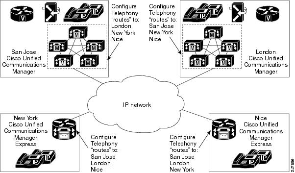
Cisco SAF provides a framework that allows networking applications to automatically discover the existence, location, and configuration of networked services within networks. This automated discovery of services replaces the manual entry of complex configurations such as dial plans, that often require repetitive configuration changes. Cisco SAF also allows applications to advertise and discover their services. Cisco SAF allows you to create a configuration once, and then have it propagate to all devices that require the information.
The figure below shows a Cisco Unified Communications Manager network using Cisco SAF.
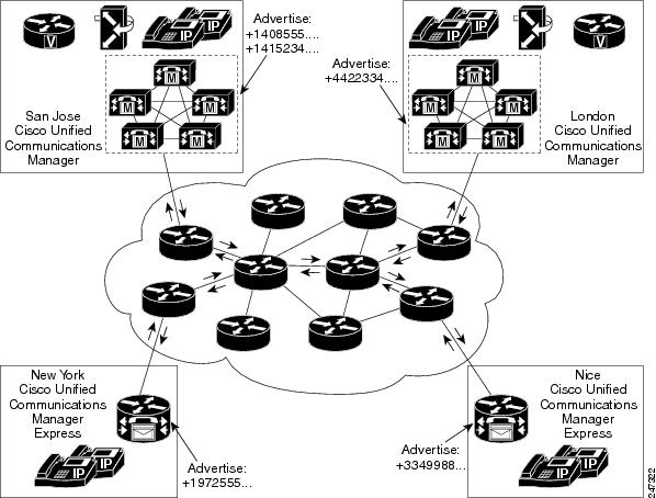
You can configure a Cisco SAF Client either on the same router as the Cisco SAF Forwarder or on an external router.
Information About Cisco SAF
- Cisco SAF Overview
- Cisco SAF Service Identifier Number Formats
- Cisco SAF and Role of Domains in a Network
- Cisco SAF Virtual Routers
- Cisco SAF Neighbor Relationships
Cisco SAF Overview
Cisco SAF provides a framework that allows applications to discover the existence, location, and configuration of networked resources within networks. Cisco SAF allows a timely and reliable awareness of the services within networks, as applications advertise and discover services on networks. Service information distributes though a network of Cisco SAF cooperative nodes that assume specific functions to efficiently distribute knowledge of services and facilitate their discovery.
A non-SAF node is any node in a network that does not understand SAF. Non-SAF nodes are called âdark netsâ and are required to traverse ISPs. Cisco SAF messages are IP-based and therefore are unaffected by dark nets.
These Cisco SAF cooperative network nodes are grouped into two major functional responsibilities:
- Cisco SAF Forwarder
- Cisco SAF Client
To configure Cisco SAF, you must configure both an SAF Forwarder and an SAF Client.
The flexibility of Cisco SAF allows you to configure a single edge router to act as a Cisco SAF Forwarder and a Cisco SAF Client, if necessary.
This section provides the following information:
- Cisco SAF Forwarder Overview
- Cisco SAF Client Overview
- Cisco SAF Client and SAF Forwarder Interaction Overview
Cisco SAF Forwarder Overview
A Cisco SAF Forwarder receives services advertised by Cisco SAF Clients, distributes the services reliably through the network, and make services available for Cisco SAF Clients to use. A Cisco SAF Forwarder:
- Ensures reliable delivery of service advertisements
- Maintains knowledge of path redundancy
- Is scalable
- Minimizes the use of network bandwidth by using targeted multicast and unicast messages.
The Cisco SAF Forwarder can propagate service advertisements to other Cisco SAF Forwarders and can propagate across a LAN, campus network, WAN, or ISP.
A basic Cisco SAF Forwarder provides the relationship between Cisco SAF Clients and the framework. A Cisco SAF Forwarder is normally located at the edges or boundaries of a network. The Cisco SAF Forwarder receives service advertisements and stores a copy before forwarding the advertisement to its neighbor SAF nodes. The Client and forwarder relationship is to maintain the advertisement. If a Client removes a service or disconnects from the forwarder node, the node will inform the framework about the services that are no longer available. When the forwarder node receives advertisements from other forwarder nodes, it will keep a copy of the entire advertisement (Header and opaque data) and forward to other SAF peers.
You can configure a Cisco SAF Forwarder on a LAN to automatically allow dynamic discovery of services to all enabled interfaces, and at the same time, specify interfaces (static configuration) you want blocked to other interfaces attempting to discover their services.
You can configure a Cisco SAF Forwarder across a non-SAF node to automatically allow dynamic discovery of services. For example, Cisco SAF Forwarders join a common peer-group. You can also create static configurations (Unicast) between pairs of Cisco SAF Forwarders.
 Note | Multicast routing is required to allow dynamic discovery of services. |
Cisco SAF Client Overview
A Cisco SAF Client is a producer (advertises to the network) or consumer of services (requests a service from the network), or both. When a Cisco SAF Client sends a register message to a Cisco SAF Forwarder, it establishes a relationship with the Cisco SAF Forwarder. The Cisco SAF Forwarder uses this register message to obtain a unique handle that distinctly identifies this Cisco SAF Client from others connected to it. Only after a Cisco SAF Client registers is it able to advertise (publish) to, or request (subscribe), services. The figure below shows a typical Cisco SAF network.

When advertising a service, a Cisco SAF Client publishes (sends) advertisements to the Cisco SAF Forwarder that contain information about the service it offers. The Cisco SAF Client can send multiple publish requests, each advertising a distinct service. The Cisco SAF Forwarder advertises all services published by the Cisco SAF Client.
When requesting a service, the Cisco SAF Client sends a request notification of services using a subscribe request. The subscribe request contains a filter that describes the set of services in which the Cisco SAF Client is interested. In response to this request, the Cisco SAF Forwarder sends the current set of services that match the filter to the Cisco SAF Client in a series of notify requests. Multiple notify requests are sent in order to provide flow control; the Cisco SAF Client must respond to each notify request before the Cisco SAF Forwarder sends the next request. As with a publish request, the Cisco SAF Client can generate multiple subscribe requests, each with a different filter. The Cisco SAF Client can also generate an unsubscribe request, which removes one of its existing subscriptions.
Cisco SAF Client and SAF Forwarder Interaction Overview
In most situations, you would configure a Cisco SAF Client application with one or more IP addresses and ports that are used to connect to a Cisco SAF Forwarder. A Cisco SAF Client initiates a TCP connection to a Cisco SAF Forwarder. Once the TCP connection is established, a Cisco SAF Client sends a register message to the Cisco SAF Forwarder. This register message uniquely identifies the Cisco SAF Client from all other Cisco SAF Clients connected to the Cisco SAF Forwarder.
Once a Cisco SAF Client registers, it advertises a service by sending a publish request to a Cisco SAF Forwarder. A Cisco SAF Client can send multiple publish requests, each advertising a distinct service. Services are identified by a unique service ID, sub-service ID, and instance ID, and are described by service data. For more information on service identifiers, refer to Cisco SAF Service Identifier Number Formats.
A Cisco SAF Forwarder advertises all services published by a Cisco SAF Client. Similarly, a Cisco SAF Client can request notification of services using a subscribe request. The subscribe request contains a filter that describes the set of services in which the Cisco SAF Client is interested. In response to this request, the Cisco SAF Forwarder sends to the Cisco SAF Client, in a series of notify requests, the current set of services that match the filter. Multiple notify requests are sent in order to provide flow control. The Cisco SAF Client must respond to each notify request before the Cisco SAF Forwarder will send the next request.
Similar to a publish request, the Cisco SAF Client can generate multiple subscribe requests, each with a different filter. The Cisco SAF Client can also generate an unsubscribe request, which removes one of its existing subscriptions.
A Cisco SAF Client and a Cisco SAF Forwarder use a shared secret for security. This shared secret consists of a username and a password. The username is an index that determines which password to use as the shared secret. When a Cisco SAF Client sends a request, it sends attributes including its username, the actual message contents, and the random password.
When a Cisco SAF Forwarder receives a request, it locates the username attribute and uses it to access its local copy of the password, and then computes similar computations the Cisco SAF Client performed. If the computations match, the Cisco SAF Client is authenticated and the request is known to be integrity protected. A Cisco SAF Forwarder can also elect to reject the request.
A Cisco SAF Forwarder requires verification regarding the liveliness of the Cisco SAF Client to advertise its services into the Cisco SAF network. A Cisco SAF Forwarder and a Cisco SAF Client exchange a liveliness timer at the time of registration. A Cisco SAF Forwarder considers a Cisco SAF Client failed if it has not seen a request from the Cisco SAF Client in a time period equal to the liveliness timer. A Cisco SAF Client ensures that the interval between requests never exceeds this value. If a Cisco SAF Client has no data to send, it generates a register message to refresh the timer on the server.
When a Cisco SAF Forwarder detects that the Cisco SAF Client has failed, it withdraws the services advertised on behalf of that Cisco SAF Client from the network and removes any subscriptions that the Cisco SAF Client had established. If the Cisco SAF Client has not failed, but just had a brief connection outage, it reconnects and re-registers with its previous handle informing the Cisco SAF Forwarder that it is operational. A Cisco SAF Client can be manually unregistered to gracefully cause a Cisco SAF Forwarder to withdraw all services and subscriptions.
Cisco SAF Service Identifier Number Formats
A service is any information that a Cisco SAF Client application wishes to advertise, that can then be used by other Cisco SAF Client applications. A service advertisement consists of service data. Service advertisements are propagated between forwarders using header data. Cisco SAF Clients that are interested in a service receive, and may inspect, service header and service data.
A service identifier number uniquely identifies the service on a network. The following example shows the format of a service identifier number:
service:sub-service:instance.instance.instance.instance
The service identifier is a 16-bit decimal identifier for the major service being advertised. A major service refers to a specific technology area, such as Cisco Unified Communications (UC). Service identifiers are assigned by Cisco to various customers requiring an SAF client.
The following example shows the service ID values for IP Everywhere and Cisco Unified Communications:
Cisco Defined Numbers
    SAF_SERVICE_ID_IPE            	= 100 	 ! IP Everywhere
    SAF_SERVICE_ID_UC            	 = 101 				 ! Unified Communications
The sub-service identifier is a 16-bit decimal identifier for the minor service being advertised. A sub-service (also referred to as a minor service) refers to the type of service within a technology. For example, within UC:
- Sub-service 1 is TDM gateway
- Sub-service 2 is hosted-DN
- Instance identifies a specific service advertisement for this kind of service. For example, service identifier 101:1:abcd.1234.ef.678 could be an advertisement of a UC (service 101) TDM gateway (sub-service 1) announced by the Communications Manager cluster in a certain location (instance abcd.1234.ef.678).
The instance identifier is a unique 128-bit number that identifies the specific service advertised.
Client teams define the use of sub-service and instance values for their applications. Clients must ensure instance uniqueness within a Cisco SAF domain.
Cisco SAF and Role of Domains in a Network
As the variety and number of network services grows, providing timely and reliable awareness of these services starts to play a more significant role in increasing productivity and efficiency. One of the biggest challenges in propagating service availability awareness over a WAN is one of scalability. As networks grow, the services offered by the devices on these networks increases. Protocols responsible for the service advertisement need to scale to handle this increased load. These protocols also need to react to rapid changes efficiently and propagate the new information in a timely manner.
Cisco SAF is designed to be a scalable solution for enterprise service locations and is capable of spanning LAN and WAN internet segments. As an enterprise solution, you can configure Cisco SAF to use domains to scale for very large networks. Just as Cisco Enhanced Interior Gateway Routing Protocol (EIGRP) defines the concept of an autonomous system in which routes can be searched for in a hierarchical manner, Cisco SAF employs the similar concept of a domain and sub-domains.
Cisco SAF provides a dynamic peer discovery and service advertisement propagation technique known as IP multicast. IP multicast requires the cooperation of IP Cisco SAF Forwarders (the devices that connect IP subnets together to form intranets). IP multicasting, however, may not be completely implemented across some intranets. In the absence of IP multicasting, Cisco SAF operates within the configured subnet, or within the groups of subnets over which IP multicast is supported.
Cisco SAF Forwarders offer two primary types of administrative domains (AD); a domain and a subdomain. A domain and a subdomain function the same with one notable exception; subdomains do not form unique neighbor relationships, but instead rely on a single peering.
Ideally, a network would only require a single domain to use for advertising all services. However, due to scaling and policy issues, some networks require the creation of multiple domains. The recommendation is to use a single domain. Consider using multiple domains when:
- More than 30,000 services are registered in a single domain
- Logical grouping of services is needed to restrict propagation of services
Closed groups are needed to prevent users from browsing services they are not allowed to access
Service redistribution allows different domains to exchange service information. Services may need to be bound to specific areas of the network, or the number of services in a given network my need to be limited. If you cannot use a single domain, service advertisement redistribution might be the solution.
Each domain on a network is separated into an administrative domain (AD). All Cisco SAF Forwarders in the same AD (running the same domain) have complete knowledge of the entire AS. A Cisco Forwarder that connects two (or more) administrative domains is known as a border Forwarder. A border Forwarder advertises service information from one AS to another AS. Proper design should also be considered if multiple border Forwarders are used to avoid loops (information learned from one AD being sent back to the same AD).
Cisco SAF Virtual Routers
Cisco EIGRP Service-Family Support extends the named configuration to allow configuration of multiple instances, which operate independently. The addition of a Virtual Router ID (VRID) to the base Cisco EIGRP packet encoding allows for multiple instances.
As each virtual router is created, a VRID is assigned to the top level router and shared with the address families and service families that are configured under it.
Cisco SAF Neighbor Relationships
Cisco SAF Forwarders can operate in networks that do not have routers that support the Cisco SAF Forwarder protocol. These networks are referred to as âdark nets.â There are two methods for configuring Cisco SAF Forwarders over IP networks that do not support Cisco SAF (IP clouds); unicast Cisco SAF neighbors and multicast Cisco SAF neighbors.
You can use a unicast configuration to provide a reliable point-to-point adjacency with neighbors. As the number of Cisco SAF Forwarders increases, you can use multicast to provide an efficient transport between multiple Cisco SAF neighbors. A single IP multicast group address can be used for multiple Cisco SAF neighbors to exchange SAF information in a peer-group.
Configuring a Cisco SAF Forwarder
- Enabling Cisco SAF
- Configuring Interface-Specific Commands for Cisco SAF
- Configuring Cisco SAF for Multi-Topology Networks
- Configuring Static Neighbor Relationships for Cisco SAF
- Configuring Stub Routing for Cisco SAF
- Configuring Route Authentication for Cisco SAF
- Configuring Logs for Neighbor Changes and Warnings
- Configuring the Percentage of Link Bandwidth Used for Cisco SAF
- Setting Metric Dampening Intervals for Cisco SAF Interfaces
- Adjusting the Interval Between Hello Packets and the Hold Time
- Disabling Split Horizon
- Setting Metric Maximum Hops
Enabling Cisco SAF
DETAILED STEPS
Configuring Interface-Specific Commands for Cisco SAF
Cisco SAF provides an inheritance precedence for interface-specific commands. Configurations made in sf-interface configuration mode have priority over specific sf-interface and factory default configurations. To configure interface-specific commands under the service-family for Cisco SAF, use the following commands:
DETAILED STEPS
Configuring Cisco SAF for Multi-Topology Networks
Use the following configuration to register clients and publish or subscribe services into a named topology. If you configure a second topology using an existing topology name, but with a different ID, it will replace the existing topology, rather than create two IDs for the same topology.
To configure Cisco SAF for multi-topology networks, use the following commands:
DETAILED STEPS
Configuring Static Neighbor Relationships for Cisco SAF
DETAILED STEPS
Configuring Stub Routing for Cisco SAF
You can configure a Cisco SAF Forwarder as a stub router. For complete information on Cisco EIGRP stub routing, refer to the Configuring EIGRP module in the Cisco IOS IP Routing: EIGRP Configuration Guide .
To create an Cisco SAF stub router, use the following commands:
DETAILED STEPS
Configuring Route Authentication for Cisco SAF
Cisco SAF route authentication provides Message Digest 5 (MD5) authentication of routing updates from the routing protocol. The MD5 keyed digest in each packet prevents the introduction of unauthorized or false routing messages from unapproved sources. To configure route authentication for Cisco SAF, use the following commands:
DETAILED STEPS
Configuring Logs for Neighbor Changes and Warnings
By default, the system logs neighbor adjacency changes to help you monitor the stability of the routing system and detect problems. If you disabled logging of such changes and want to reenable the logging, use the following commands:
DETAILED STEPS
Configuring the Percentage of Link Bandwidth Used for Cisco SAF
By default, packets consume a maximum of 50 percent of the link bandwidth, as configured with the bandwidth interface configuration command. You may want to change the value if a different level of link utilization is required or if the configured bandwidth does not match the actual link bandwidth (it may have been configured to influence route metric calculations). Use the following commands to configure the percentage of link bandwidth used for Cisco SAF.
DETAILED STEPS
Setting Metric Dampening Intervals for Cisco SAF Interfaces
Because metric components can be changed rapidly, the frequency of the changes can have an impact on the network. Frequent changes require that prefixes learned though the SAF interface be updated and sent to all adjacencies. This update can result in further updates and in a worst-case scenario, cause network-wide churn. To prevent such effects, metrics can be dampened or thresholds set so that any change that does not exceed the dampening threshold is ignored.
Network changes that cause an immediate update include any change in a metric that results in the router selecting a new nexthop or a down interface or router.
Dampening the metric changes can be configured based on a change or on a time interval.
If the dampening method is:
- Change-based, changes in routes learned though a specific interface or in the metrics for a specific interface will not be advertised to adjacencies until the computed metric changes from the last advertised value are significant enough to cause an update to be sent.
- Interval-based, changes in routes learned though a specific interface or in the metrics for a specific interface will not be advertised to adjacencies until the specified interval is met or unless the change results in a new route path selection. When the timer expires, routes that have outstanding changes to report are sent. If a route changes and the final metric of the route matches the last updated metric, no updated routes are sent.
Refer to the following sections for information on configuring change-based and interval-based metric dampening configurations.
Change-based Dampening Configuration
Use the following commands to set the maximum change-based dampening percentage for Cisco SAF interfaces.
DETAILED STEPS
Interval-based Dampening Configuration
Use the following commands to configure the interval-based dampening for Cisco SAF interfaces. The value you configure sets the interval when updates occur for topology changes that affect Cisco SAF interfaces and peers.
DETAILED STEPS
Adjusting the Interval Between Hello Packets and the Hold Time
Routing devices periodically send hello packets to each other to dynamically learn of other routers on their directly attached networks. This information is used to discover neighbors and to learn when neighbors become unreachable or inoperative.
By default, hello packets are sent every 5 seconds. The exception is on low-speed, nonbroadcast multiaccess (NBMA) media on which the default hello interval is 60 seconds. Low speed is considered to be a rate of T1 or slower as specified in the bandwidth interface configuration command. The default hello interval remains at 5 seconds for high-speed NBMA networks. Note that for the purposes of Frame Relay and Switched Multimegabit Data Service (SMDS), networks may or may not be considered to be NBMA. These networks are considered NBMA if the interface has not been configured to use physical multicasting; otherwise they are not considered NBMA.
The hold time is advertised in hello packets and indicates to neighbors the length of time they should consider the sender valid. The default hold time is three times the hello interval, or 15 seconds. For slow-speed NBMA networks, the default hold time is 180 seconds. On congested and large networks, the default hold time might not be sufficient time for all routers to receive hello packets from their neighbors. In this case, you may want to increase the hold time. Do not adjust the hold time without advising your technical support personnel. To change the hold time on a specific interface for a particular routing process designated by the autonomous system number, use the hold time command.
You can adjust the interval between hello packets and the hold time. To change the interval between hello packets and the hold time, use the following commands in interface configuration mode.
DETAILED STEPS
Disabling Split Horizon
When split horizon is enabled on an interface, it blocks route information (such as update and query packets) from being advertised by a router out of any interface from which that information originates. Controlling update and query packets in this manner reduces the possibility of routing loops.
This behavior usually optimizes communications among multiple routing devices, particularly when links are broken. However, with nonbroadcast networks (such as Frame Relay and SMDS), situations can arise for which this behavior is less than ideal. For these situations, including networks in which you have Cisco SAF configured, you may want to disable split horizon.
By default, split horizon is enabled on all interfaces. To disable split horizon, use the no split-horizon command in interface configuration mode.
DETAILED STEPS
Setting Metric Maximum Hops
Maximum hops limits the number of hops a service can propagate to advertise its service. The default number of maximum hops is 100.
To limit the number of hops used to advertise a service, use the following commands:
DETAILED STEPS
Configuring a Cisco SAF Client
This section describes the tasks to configure a Cisco Service Advertisement Framework (Cisco SAF) Client.
Cisco SAF Clients connect to the Cisco SAF network in one of two ways:
- Reside on the same router as a Cisco SAF Forwarder, in which case the Cisco SAF Client uses an internal API to connect to a Cisco SAF Forwarder.
- Be external to a Cisco SAF Forwarder. In this configuration, the SAF Client is referred to as a Cisco SAF External Client, and it requires a protocol interface for connecting to the Cisco SAF Forwarder.
Prerequisites
Before configuring:
- Cisco SAF Clients, you should understand the concepts in the Cisco SAF Client_Overview.
- Neighbor relationships for Cisco SAF External Clients located on separate LANs, ensure that you have IP routing configured between each Cisco External Client.
Configuring a Cisco SAF External Client
DETAILED STEPS
Configuring Dynamic Neighbors
When neighbors are not adjacent, normal Cisco SAF peering mechanisms cannot be used to exchange SAF information over the networking cloud. The neighbors are often multiple hops away, and separated by dark nets (routers not running SAF).
To support this type of network, SAF provides the neighbor command, which allows remote neighbors to be configured and sessions established though unicast packet transmission. However, as the number of Forwarders needing to exchange SAF information over the networking cloud increases, unicast SAF neighbor definitions may become cumbersome to manage. Each neighbor has to be manually configured, resulting in increased operational costs.
To better accommodate deployment of these topologies, ease configuration management, and reduce operational costs, the Dynamic Neighbors feature provides support for the dynamic discovery of remote unicast and multicast neighbors (referred to as âremote neighborsâ). Remote neighbor support allows Cisco SAF peering to one or more remote neighbors, which may not be known at the time the router is configured, thus reducing configuration management.
This section contains the following major topics:
- Neighbor Types
- Remote Neighbor Session Policy
- Remote Unicast-Listen (Point-to-Point) Neighbors
- Remote Multicast-Group (Multipoint-to-Multipoint) Neighbors
- Inheritance and Precedence of the Remote Neighbor Configurations
- Prerequisites
- Restrictions
- Configuring Cisco SAF Dynamic Neighbors
Neighbor Types
The following terms are used when describing neighbor types:
- Local Neighbor--A neighbor that is adjacent on a shared subnet (or common subnet) and uses a link-local multicast address for packet exchange. This is the default type of neighbor in Cisco SAF.
- Static Neighbor--Any neighbor that uses unicast to communicate, is one hop away, is on a common subnet, and whose IP address has been specified using the neighborip-address command.
- Remote Neighbor--Any neighbor that is multiple hops away, including Remote Static Neighbors.
- Remote Static Neighbor--Any neighbor that uses unicast to communicate, is multiple hops away, and whose IP address has been specified using the neighborip-address command.
- Remote Multicast-Group--Any neighbor that is multiple hops away, but does not have its IP address manually configured using the neighborip-address command, and uses a configured multicast group address for packet exchange.
- Remote Unicast-listen (or simply Unicast-listen)--Any neighbor that uses unicast to communicate, is multiple hops away, and whose IP address has not been configured using the neighborip-address command.
Remote Neighbor Session Policy
When using remote unicast-listen or remote multicast-group neighbor configurations, SAF neighbor IP addresses are not pre-defined, and neighbors may be many hops away. A router with this configuration could peer with any router that sends a valid HELLO packet. Because of security considerations, this open aspect requires policy capabilities to limit peering to valid routers and to restrict the number of neighbors to limit resource consumption. This capability is accomplished using the following manually configured parameters, and takes effect immediately.
- Neighbor Filter List
- Maximum Remote Neighbors
- Configuration Changes for Neighbor Filter List and Maximum Remote Neighbors
Neighbor Filter List
The optional allow-list keyword, available in the remote-neighbors command, enables you to use an access list (Access Control List) to specify the remote IP addresses from which Cisco SAF neighbor connections may be accepted. If you do not use the allow-list keyword, then all IP addresses (permit any) will be accepted.
The Access Control List (ACL) defines a range of IPv4 or IPv6 IP addresses with the following conditions:
- Any neighbor that has a source IP address that matches an IP address in the access-list will be allowed (or denied) based on the user configuration.
- If the allow-list keyword is not specified, any IP address will be permitted (permit any).
- The allow-list keyword is supported only for remote multicast-group and unicast-listen neighbors. It is not available for static, remote static, or local neighbors.
- Incoming Cisco SAF packets that do not match the specified access list will be rejected.
Maximum Remote Neighbors
The optional max-neighborskeyword, available in the remote-neighbors command, enables you to specify a maximum number of remote neighbors that Cisco SAF can create using the remote neighbor configurations. When the maximum number of remote neighbors has been created for a configuration, Cisco SAF rejects all subsequent connection attempts for that configuration. This option helps to protect against denial-of-service attacks that attempt to create many remote neighbors in an attempt to overwhelm router resources.
The max-neighbors configuration option has the following conditions:
- This option is supported only for remote multicast-group or unicast-listen neighbors. It is not available for local, static, or remote static neighbors.
- There is no default maximum. If you do not specify a maximum number of remote neighbors, the number of remote neighbors is limited only by available memory and bandwidth.
- Reducing the maximum number of remote neighbors to a number less than the current sessions will result in the neighbors (in no specific order) being dropped until the count reaches the new limit.
Configuration Changes for Neighbor Filter List and Maximum Remote Neighbors
When the allow-list or max-neighbors configurations are changed, any existing remote Cisco SAF sessions that are no longer allowed by the new configuration will be removed automatically and immediately. Pre-existing neighbors that are still allowed by the new configuration will not be affected.
Remote Unicast-Listen (Point-to-Point) Neighbors
For configurations in which multiple remote neighbors peer with a single hub (point-to-point), the hub can be configured for remote unicast-listen peering using the remote-neighbors command to allow the remote neighbors to peer with the hub without having to manually configure the remote neighbor IP addresses on the hub.
When configured with this command, the hub router:
- Uses its interface IP address as the source IP address for any unicast transmissions. This IP address must be routable.
- Requires neighbors peering with the hub to be configured using the neighborip-address loopback loopback-interface-number remotemaximum-hops command where ip-address is the unicast address of the local router interface IP address.
- Listens for unicast HELLO packets on the interface specified in the remote-neighbor command.
- Accepts a unicast HELLO packet if it is in the IP address range configured using the allow-list keyword, or any unicast HELLO packet if an allow list is not defined.
- Rejects multicast HELLO packets from any neighbor that is also sending unicast HELLO packets and is permitted by the unicast allow-list (or all neighbors if an allow-list is not defined).
- Begins normal neighbor establishment using the IP addresses of the remote neighbors for packet transmission once the neighbor relationship is established.
Remote Multicast-Group (Multipoint-to-Multipoint) Neighbors
Multicast can be used to provide an efficient transport between multiple Cisco SAF neighbors. A single multicast-group address can be used for multiple Cisco SAF neighbors to exchange information within the same multicast-group. To configure multipoint-to-multipoint configurations, use the multicast-group keyword available in the remote neighbors command.
When configured with this command, the router:
- Uses the interface IP address as the source IP address for any unicast transmissions. This IP address must be routable.
- Uses the configured multicast-group address for all multicast packets sent and received.
- Requires all forwarders and routers, which form the multipoint-to-multipoint neighbor relationships, to be configured using the same multicast-group IP address.
- Requires multicast forwarding for the defined multicast-group address to be configured and functional for packet delivery.
Inheritance and Precedence of the Remote Neighbor Configurations
Static neighbors configured with the neighborip-address or the neighborip addressremote commands take precedence over the remote neighbors that are created as a result of the remote-neighbors command. If the remote IP address of an incoming unicast Cisco SAF connection matches both a static neighbor and the remote unicast-listen neighbor access list, the static neighbor is used and no remote unicast-listen neighbor is created. If you configure a new static neighbor while a remote neighbor for the same remote IP address already exists, Cisco SAF automatically removes the remote unicast-listen neighbor.
Remote unicast-listen neighbors take precedence over remote multicast-group neighbors. If Cisco SAF is receiving both unicast and multicast HELLOs from the same remote IP address targeted at the same local interface, the neighbor will be treated as unicast (unicast-listen) rather than multicast (multicast-group) for packet exchange.
Prerequisites
Before configuring SAF dynamic neighbors, ensure that when using:
- Unicast-listen mode--IP connectivity (reachability) exists between routers that need to do dynamic peering.
- Multicast-group mode--Multicast is running on the network.
- allow-list keyword--The configured Access Control List that will specify the remote IP addresses from which EIGRP neighbor connections may be accepted.
Restrictions
- The remote-neighbors command requires a loopback as a source interface.
- Only named ACLs (Access Control Lists) are permitted with the allow-list keyword. Numbered ACLs configured are not permitted.
-
Within a service-family:
- Only one remote-neighbors unicast-listen command and one remote-neighbors multicast-group command may be configured per interface. (For example, you cannot configure remote-neighbors source Loopback1 multicast-group 224.1.1.1 and remote-neighbors source Loopback1 multicast-group 224.1.1.2.) If you want to configure multiple different multicast-group addresses in the same service-family, you need to use multiple source interfaces.
- A multicast-group address may only be associated to a single source interface. (For example, you cannot configure remote-neighbors source Loopback1 multicast-group 224.1.1.1 and remote-neighbors source Loopback2 multicast-group 224.1.1.1.)
Configuring Cisco SAF Dynamic Neighbors
DETAILED STEPS
Configuring Capabilities Manager
The Service Routing Capabilities Manager feature enables Cisco IOS routing platforms to collect their network services (capability) information, store the information in their local Network Information Base (NIB), and then advertise those capabilities to other routers in the network that also have a SAF (Service Advertisement Framework) Forwarder configured and Capabilities Manager enabled. A capability designates a feature or service in the network, such as the presence of hardware, a software feature, or the configuration of a network service (IPv4 or IPv6). A NIB is a database located on each routing platform in which capabilities information is stored.
Using Capabilities Manager, you can access capability information without having to connect to each router to access the routerâs information. For example, if you want to know which software version is running on a router, you must log in to that router and enter a show command. By enabling Capabilities Manager on routers in the network for which you wish to access capability information, you would only need to log in to one router and enter one show command to display the software versions for all routers.
When a new router that is running SAF and Capabilities Manager is added to the network, the router will automatically:
- Capabilities Discovery
- Interoperability with SAF Forwarder
- Capabilities Information
- Capabilities Groups
- XML Schema for Capabilities Data
- Prerequisites for Configuring Capabilities Manager
- Disabling and Enabling and Capabilities Manager
- Displaying Capabilities Manager Information
- Clearing Registered Capabilities Information
Capabilities Discovery
Capabilities Manager is enabled by default at system startup. At startup, it registers as a Service Routing Client and proceeds to discover various capabilities of the hardware and software platform. Capabilities Manager only discovers whether a capability is supported on the local system. It does not discover whether the capability is configured or enabled or discover any other information about the capability for other routers in the network.
Capabilities information will be installed into the local Network Information Base (NIB) as service routing data and made available for advertisement by any SAF Forwarder to the Service Routing network. Capabilities information is passed to the Service Routing infrastructure in XML format and stored in the local NIB.
Interoperability with SAF Forwarder
Capabilities Manager does not advertise capabilities information to the Service Routing network. A SAF Forwarder performs the functions to distribute capabilities information. However, a SAF Forwarder is not required for Capabilities Manager to function. If a SAF Forwarder is not configured, the capabilities information is bound to the local router and is not distributed to other routers in the network. When a SAF Forwarder is configured, it will distribute all capabilities information by default.
Capabilities Information
Capabilities information is installed in the Network Information Base (NIB) as service routing data. It is identified by a SAF address in the form of:
- service IDâCapabilities Manager uses service ID 100.
- subservice IDâCapability group ID. The subservice ID indicates the group ID of the capabilities data type.
- Instance numberâUnique identifier for the local router. It is assigned in order of the hardware serial number, default MAC address, IPv4 router ID, or IPv6 router ID.
Capabilities Groups
Capabilities Manager classifies capabilities by group to facilitate query and retrieval, and assigns each group a unique ID. Capabilities Manager provides the following capability groups:
Hardware Group Information
Hardware information is designated as group ID 1. Group 1 provides the following capabilities information, when available. All hardware information may not be available on each platform that supports Capabilities Manager.
XML Schema for Capabilities Data
If you have an Extensible Messaging Client Protocol (XMCP) client (external client) connected to a SAF Forwarder, you can subscribe to the Capabilities Manager, which is service ID 100. The data can be interpreted using the following XML schema:
<?xml version="1.0" encoding="UTF-8"?>
<xs:schema xmlns:xs='http://www.w3.org/2001/XMLSchema'>
<xs:element name="Capabilities" type="CapabilitiesType" />
<xs:complexType name="CapabilitiesType">
<xs:sequence>
<xs:element ref="Group" minOccurs="1" maxOccurs="unbounded" />
</xs:sequence>
</xs:complexType>
<xs:element name="Group" type="GroupType" />
<xs:complexType name="GroupType">
<xs:sequence>
<xs:element ref="Capability" minOccurs="1" maxOccurs="unbounded" />
</xs:sequence>
<xs:attribute name="Name" type="xs:normalizedString" use="required" />
</xs:complexType>
<xs:element name="Capability" type="CapabilityType" />
<xs:complexType name="CapabilityType">
<xs:sequence>
<xs:element name="Value" type="xs:normalizedString" />
</xs:sequence>
<xs:attribute name="Name" type="xs:normalizedString" use="required" />
</xs:complexType>
</xs:schema>
Example:
<Capabilities>
<Group Name="HARDWARE">
<Capability Name="HostName">
<Value>R100</Value>
</Capability>
<Capability Name="Platform">
<Value>Solaris Unix (Sparc) processor</Value>
</Capability>
<Capability Name="MainMemorySize">
<Value>63683Kbytes</Value>
</Capability>
</Group>
<Group Name="SOFTWARE">
<Capability Name="HostName">
<Value>R100</Value>
</Capability>
<Capability Name="Software">
<Value>Cisco IOS Software</Value>
</Capability>
<Capability Name="Image">
<Value>Solaris Software (UNIX-ADVENTERPRISE-M)</Value>
</Capability>
<Capability Name="Version">
<Value>Experimental Version 15.1(20110323:093227)</Value>
</Capability>
<Capability Name="ipmulticast">
<Value>Subsystem loaded</Value>
</Capability>
<Capability Name="eigrp_ipv4">
<Value>Subsystem loaded</Value>
</Capability>
</Group>
</Capabilities>
Prerequisites for Configuring Capabilities Manager
The following prerequisites apply to the Capabilities Manager feature:
- To ensure that a router has Capabilities Manager available, enter the show service-routing plugin capman command.
- To enable a router to distribute its capabilities information, configure a SAF Forwarder on the router.
- To view capabilities information present on other routers in the network, configure a SAF Forwarder
Disabling and Enabling and Capabilities Manager
Capabilities Manager is enabled by default. You can disable and reenable Capabilities Manager at any time.
- Disabling Capabilities Manager will remove all the capabilities information that is installed in the local Network Information Base (NIB) and unregister the information from Service Routing.
- Re-enabling Capabilities Manager will rediscover capabilities and provide information to the local NIB and to the Service Routing network.
Perform this task to disable and reenable Capabilities Manager.
DETAILED STEPS
Displaying Capabilities Manager Information
To display information about Capabilities Manager, use the following commands in privileged EXEC mode.
DETAILED STEPS
Clearing Registered Capabilities Information
Perform this task to clear current capabilities information from the NIB. Once the NIB is cleared, Capabilities Manager will automatically rediscover new capabilities.
DETAILED STEPS
Displaying Cisco SAF Statistics
DETAILED STEPS
Deleting Information from a Cisco SAF Configuration
To delete service-family information from a Cisco SAF configuration, use the following commands in EXEC mode.
DETAILED STEPS
Configuration Examples for Cisco SAF
- Enabling Cisco SAF Example
- Configuring Cisco SAF Interfaces Examples
- Configuring Cisco SAF Topology Example
- Configuring Cisco SAF Stub Routing Example
- Configuring Cisco SAF with IP-RIP Example
- Configuring Cisco SAF with OSPF Example
- Configuring Cisco SAF with EIGRP Example
- Configuring Cisco SAF Forwarders Located on Separate LANs Example
- Configuring a Centralized Cisco SAF Forwarder Example
- Configuring a Cisco SAF Client Examples
- Configuring Logs for Neighbor Changes and Warnings Example
- Configuring Cisco Unified Communications Manager as a Cisco SAF Client Example
- Configuring Cisco SAF Dynamic Neighbors Examples
Configuring Cisco SAF Interfaces Examples
The following example places the router in service-family configuration mode and enables all interfaces.
Router(config)# router eigrp saf Router(config-router)# service-family ipv4 autonomous-system 4533 Router(config-router-sf)# sf-interface default Router(config-router-sf-interface)# no shutdown
The following example places the router in service-family configuration mode and enables Ethernet interface 0/0.
Router(config)# router eigrp saf Router(config-router)# service-family ipv4 autonomous-system 4533 Router(config-router-sf)# sf-interface ethernet0/0
The following example places the router in service-family configuration mode and enables SAF on all interfaces, except the Ethernet0/0 interface.
Router(config)# router eigrp saf Router(config-router)# service-family ipv4 autonomous-system 3 Router(config-router-sf)# interface default Router(config-router-sf)# sf-interface ethernet0/0 Router(config-router-sf-interface)# shutdown Router(config-router-sf-interface)# end
The following example places the router in service-family configuration mode and enables SAF on the Ethernet2/0 and Ethernet2/1 interfaces and disables all other interfaces.
Router(config)# router eigrp saf Router(config-router)# service-family ipv4 autonomous-system 2 Router(config-router-sf)# sf-interface default Router(config-router-sf-interface)# shutdown Router(config-router-sf-interface)# sf-interface ethernet2/0 Router(config-router-sf-interface)# no shutdown Router(config-router-sf-interface)# sf-interface ethernet2/1 Router(config-router-sf-interface)# no shutdown Router(config-router-sf-interface)# end
Configuring Cisco SAF Topology Example
The following examples configures a Cisco SAF topology base.
Router(config)# router eigrp saf Router(config-router)# service-family ipv4 autonomous-system 4533 Router(config-router-sf)# sf-interface default Router(config-router-sf-interface)# no shutdown Router(config-router-sf-interface)# topology base
Configuring Cisco SAF with IP-RIP Example
The following configuration example enables Cisco SAF with IP-RIP routing on network 10.0.0.0.
Router(config)# router eigrp saf
Router(config-router)# service-family ipv4 autonomous-system 4533
Router(config-router-sf)# topology base
Router(config-router-sf-topology)# exit-sf-topology
Router(config-router-sf)# exit service-family
Router(config-router)# router rip
Router(config-router)# network 10.0.0.0
Configuring Cisco SAF with OSPF Example
The following configuration example enables Cisco SAF with OSPF routing on network 10.0.0.0, area 0.
Router(config)# router eigrp saf
Router(config-router)# service-family ipv4 autonomous-system 4533
Router(config-router-sf)# topology base
Router(config-router-sf-topology)# exit-sf-topology
Router(config-router-sf)# exit service-family
Router(config-router)# router ospf 787
Router(config-router)# network 10.0.0.0  0.0.0.255 area 0
Configuring Cisco SAF with EIGRP Example
The following configuration example enables Cisco SAF with EIGRP routing on network 10.0.0.0.
Router(config)# router eigrp saf
Router(config-router)# service-family ipv4 autonomous-system 6476
Router(config-router-sf)# network 10.0.0.0  0.0.0.255
Router(config-router-sf)# topology base
Router(config-router-sf-topology)# exit-af-topology
Router(config-router-sf)# exit-service-family
Router(config-router)# service-family ipv4 autonomous-system 4533
Router(config-router-sf)# topology base
Note | There is no requirement to run routing over the same interfaces or networks in which services are distributed, however this could lead to services being distributed to areas where reachability is not guaranteed. |
Configuring Cisco SAF Forwarders Located on Separate LANs Example
The following examples configures two Cisco SAF Forwarders located on separate LANs.
Note | Use loopback mode to configure remote neighbors. |
Cisco SAF Forwarder 1:
Router(config)# interface loopback1
Router(config-if)# ip address 10.1.1.1 255.255.255.255
Router(config-if)# exit
Router(config)# router eigrp saf
Router(config-router)# service-family ipv4 autonomous-system 1
Router(config-router-sf)# neighbor 10.2.2.2 loopback1 remote 10
Cisco SAF Forwarder 2:
Router(config)# interface loopback1
Router(config-if)# ip address 10.2.2.2 255.255.255.255
Router(config-if)# exit
Router(config)# router eigrp saf
Router(config-router)# service-family ipv4 autonomous-system 1
Router(config-router-sf)# neighbor 10.1.1.1 loopback1 remote 10
Note | This example assumes IP routing is configured between the two routers and the routers can ping both loopbacks. |
Configuring a Centralized Cisco SAF Forwarder Example
The following example configures a centralized Cisco SAF Forwarder from which all service advertisements will send to neighbors on IP addresses 10.4.15.5 and 10.4.15.1.
Router(config)# router eigrp saf
Router(config-router)# service-family ipv4 autonomous-system 4533
Router(config-router-sf)# sf-interface loopback0
Router(config-router-sf-interface)# no split-horizon
Router(config-router-sf-interface)# exit-sf-interface
Router(config-router-sf)# topology base
Router(config-router-sf-topology)# exit-sf-topology
Router(config-router-sf)# neighbor 10.4.15.5 Loopback0 remote 20
Router(config-router-sf)# neighbor 10.4.15.1 Loopback0 remote 20
Router(config-router-sf)# exit-service-family
Configuring a Cisco SAF Client Examples
The following example configures a Cisco SAF External Client named example , with a username of username_example , a password of password_example , and a keepalive setting of 360000 seconds.
Router(config)# router eigrp saf
Router(config-router)# service-family ipv4 autonomous-system 4533
Router(config-router-sf)# topology base
Router(config-router-sf-topology)# external-client example
Router(config-router-sf-topology)# exit-sf-topology
Router(config-router-sf)# exit-service-family
Router(config-router)# exit
Router(config)# service-family external-client listen ipv4 3444
Router(config-external-client)# external-client example
Router(config-external-client-mode)# username
 username_example
Router(config-external-client-mode)# password
 password_example
Router(config-external-client-mode)# keepalive
 360000
The following example configures eight Cisco SAF External Clients named example1 through example5 , with usernames of username_example1 through username_example5 , passwords of password_example1 through password_example5 , and keepalive settings of 360000 seconds.
Router(config)# router eigrp saf
Router(config-router)# service-family ipv4 autonomous-system 4533
Router(config-router-sf)# topology base
Router(config-router-sf-topology)# external-client example1
Router(config-router-sf-topology)# external-client example2
Router(config-router-sf-topology)# external-client example3
Router(config-router-sf-topology)# external-client example4
Router(config-router-sf-topology)# external-client example5
Router(config-router-sf-topology)# exit-sf-topology
Router(config-router-sf)# exit-service-family
Router(config-router)# exit
Router(config)# service-family external-client listen ipv4 3444
Router(config-external-client)# external-client example1
Router(config-external-client-mode)# username
 username_example1
Router(config-external-client-mode)# password
 password_example1
Router(config-external-client-mode)# keepalive
 360000
Router(config-external-client-mode)# external-client example2
Router(config-external-client-mode)# username
 username_example2
Router(config-external-client-mode)# password
 password_example2
Router(config-external-client-mode)# keepalive
 360000
Router(config-external-client-mode)# external-client example3
Router(config-external-client-mode)# username
 username_example3
Router(config-external-client-mode)# password
 password_example3
Router(config-external-client-mode)# keepalive
 360000
Router(config-external-client-mode)# external-client example4
Router(config-external-client-mode)# username
 username_example4
Router(config-external-client-mode)# password
 password_example4
Router(config-external-client-mode)# keepalive
 360000
Router(config-external-client-mode)# external-client example5
Router(config-external-client-mode)# username
 username_example5
Router(config-external-client-mode)# password
 password_example5
Router(config-external-client-mode)# keepalive
 360000
Configuring Logs for Neighbor Changes and Warnings Example
By default, the system logs neighbor adjacency changes to help you monitor the stability of the routing system and detect problems. If you disabled logging of such changes and want to reenable the logging, use the commands as shown in the following example:
Router(config)# router eigrp saf
Router(config-router)# service-family ipv4 autonomous-system 4453
Router(config-router-sf)# eigrp log-neighbor-changes
Router(config-router-sf)# eigrp log-neighbor-warnings 60
Router(config-router-sf)# exit-service-family
Configuring Cisco Unified Communications Manager as a Cisco SAF Client Example
The following example configures a Cisco Unified Communications Manager as a Cisco SAF Client.
Router(config)# router eigrp virtual-router
Router(config-router)# service-family ipv4 autonomous-system 4533
Router(config-router-sf)# topology
 base
Router(config-router-sf-topology)# external-client cucm
Router(config-router-sf-topology)# exit-sf-topology
Router(config-router-sf)# exit service-family
Router(config-router)# exit
Router(config)# service-family external-client listen ipv4 3444
Router(config-router-sf)# topology base
Router(config-router-sf-topology)# external-client cucm basename
Router(config-external-client)# username cucm
Router(config-external-client)# password example
Router(config-external-client)# keepalive 360000
Configuring Cisco SAF Dynamic Neighbors Examples
The following examples show how to configure both routers involved in the neighbor relationship.
This example uses the unicast-listen keyword to configure remote neighbors to accept inbound connections from IP addresses that match the access list myNeighborList.
Router1(config)# interface Loopback1
Router1(config-if)# ip address 10.1.1.1 255.255.255.255
Router1(config-if)# exit
Router1(config)# ip access-list standard myNeighborList
Router1(config-std-nacl)# permit 10.0.0.0 0.255.255.255
Router1(config-std-nacl)# exit
Router1(config)# router eigrp virtual-name
Router1(config-router)# service-family ipv4 autonomous-system 4453
Router1(config-router-sf)# remote-neighbors source Loopback1 unicast-listen allow-list myNeighborList
Router2(config)# interface Loopback2
Router2(config-if)# ip address 10.2.2.2 255.255.255.255
Router2(config-if)# exit
Router2(config)# router eigrp virtual-name
Router2(config-router)# service-family ipv4 autonomous-system 4453
Router2(config-router-sf)# neighbor 10.1.1.1 Loopback2 remote 20
This example uses the multicast-group keyword to use IP multicast to discover remote neighbors and form remote neighbor relationships. It also specifies 30 as the maximum number of inbound connections from remote neighbors that a member of the multicast group may accept.
Router1(config)# interface Loopback1
Router1(config-if)# ip address 10.1.1.1 255.255.255.255
Router1(config-if)# ip pim sparse-mode
Router1(config-if)# exit
Router1(config)# router eigrp virtual-name
Router1(config-router)# service-family ipv4 autonomous-system 4453
Router1(config-router-sf)# remote-neighbors source Loopback1 multicast-group 224.44.56.1 max-neighbors 30
Router2(config)# interface Loopback2
Router2(config-if)# ip address 10.2.2.2 255.255.255.255
Router2(config-if)# ip pim sparse-mode
Router2(config-if)# exit
Router2(config)# router eigrp virtual-name
Router2(config-router)# service-family ipv4 autonomous-system 4453
Router2(config-router-sf)# remote-neighbors source Loopback2 multicast-group 224.44.56.1 max-neighbors 30
Additional References
The following sections provide references related to the Service Advertisement Framework technology.
MIBs
Technical Assistance
|
Description |
Link |
|---|---|
|
The Cisco Support and Documentation website provides online resources to download documentation, software, and tools. Use these resources to install and configure the software and to troubleshoot and resolve technical issues with Cisco products and technologies. Access to most tools on the Cisco Support and Documentation website requires a Cisco.com user ID and password. |
Feature Information for Cisco Service Advertisement Framework
The following table provides release information about the feature or features described in this module. This table lists only the software release that introduced support for a given feature in a given software release train. Unless noted otherwise, subsequent releases of that software release train also support that feature.
Use Cisco Feature Navigator to find information about platform support and Cisco software image support. To access Cisco Feature Navigator, go to www.cisco.com/go/cfn. An account on Cisco.com is not required.
| Table 1 | Feature Information for Cisco Service Advertisement Framework |
|
Feature Name |
Software Releases |
Feature Configuration Information |
|---|---|---|
|
Cisco Service Advertisement Framework |
15.0M, 12.2(33)SRE, 12.2(33)XNE, 15.1T, 12.2(33)SXI4, 15.0(1)S, 15.1(2)S, 12.2(50)SY, 15.2(1)T, 15.1(3)S |
This feature allows applications to discover the existence, location, and configuration of networked resources within networks, and provides a timely and reliable awareness of the services within networks, as applications advertise and discover services on networks. This feature was introduced in Cisco IOS Release 15.0M. The following commands were introduced in this feature:
|
|
Cisco Service Advertisement Framework |
15.0M, 12.2(33)SRE, 12.2(33)XNE, 15.0(1)S, 15.1(2)S |
The following commands were modified in this feature:
In Release 15.1(2)S, support was added for the Dynamic Neighbor feature. The following commands were introduced or modified: authentication mode, remote-neighbors source, show eigrp service-family external-client. |
Cisco and the Cisco Logo are trademarks of Cisco Systems, Inc. and/or its affiliates in the U.S. and other countries. A listing of Cisco's trademarks can be found at www.cisco.com/go/trademarks. Third party trademarks mentioned are the property of their respective owners. The use of the word partner does not imply a partnership relationship between Cisco and any other company. (1005R)
Any Internet Protocol (IP) addresses and phone numbers used in this document are not intended to be actual addresses and phone numbers. Any examples, command display output, network topology diagrams, and other figures included in the document are shown for illustrative purposes only. Any use of actual IP addresses or phone numbers in illustrative content is unintentional and coincidental.