
 Feedback
Contents
- RSVP-Previous Hop Overwrite
- Finding Feature Information
- Prerequisites for RSVP-Previous Hop Overwrite
- Restrictions for RSVP-Previous Hop Overwrite
- Information About RSVP-Previous Hop Overwrite
- Feature Overview of RSVP-Previous Hop Overwrite
- Benefits of RSVP-Previous Hop Overwrite
- How to Configure RSVP-Previous Hop Overwrite
- Configuring a Source Address or a Source Interface
- Verifying the PHOP Configuration
- Configuration Examples for RSVP-Previous Hop Overwrite
- Examples Configuring RSVP-Previous Hop Overwrite
- Examples Verifying RSVP-Previous Hop Overwrite Configuration
- Additional References
- Feature Information for RSVP-Previous Hop Overwrite
- Glossary
RSVP-Previous Hop Overwrite
The RSVP--Previous Hop Overwrite feature allows you to configure a Resource Reservation Protocol (RSVP) router, on a per interface basis, to populate an address other than the native interface address in the previous hop (PHOP) address field of the PHOP object when forwarding a PATH message onto that interface. You can configure the actual address for the router to use or an interface, including a loopback, from which to borrow the address.
- Finding Feature Information
- Prerequisites for RSVP-Previous Hop Overwrite
- Restrictions for RSVP-Previous Hop Overwrite
- Information About RSVP-Previous Hop Overwrite
- How to Configure RSVP-Previous Hop Overwrite
- Configuration Examples for RSVP-Previous Hop Overwrite
- Additional References
- Feature Information for RSVP-Previous Hop Overwrite
- Glossary
Finding Feature Information
Your software release may not support all the features documented in this module. For the latest feature information and caveats, see the release notes for your platform and software release. To find information about the features documented in this module, and to see a list of the releases in which each feature is supported, see the Feature Information Table at the end of this document.
Use Cisco Feature Navigator to find information about platform support and Cisco software image support. To access Cisco Feature Navigator, go to www.cisco.com/go/cfn. An account on Cisco.com is not required.
Prerequisites for RSVP-Previous Hop Overwrite
You must configure RSVP on one or more interfaces on at least two neighboring routers that share a link within the network.
Restrictions for RSVP-Previous Hop Overwrite
- This feature is supported only on integrated services routers (ISRs).
- Unnumbered IP addresses are not allowed.
Information About RSVP-Previous Hop Overwrite
Feature Overview of RSVP-Previous Hop Overwrite
An RSVP PATH message contains a PHOP object that is rewritten at every RSVP hop. The object's purpose is to enable an RSVP router (R1) sending a PATH message to convey to the next RSVP router (R2) downstream that the previous RSVP hop is R1. R2 uses this information to forward the corresponding RESV message upstream hop-by-hop towards the sender.
The current behavior in Cisco IOS software is that an RSVP router always sets the PHOP address to the IP address of the egress interface onto which the router transmits the PATH message.
There are situations where, although some IP addresses of R1 are reachable, the IP address of its egress interface is not reachable from a remote RSVP router R2. This results in the corresponding RESV message generated by R2 never reaching R1 and the reservation never being established.
The figure below shows a sample network in which the preceding scenario occurs and no reservation is established.
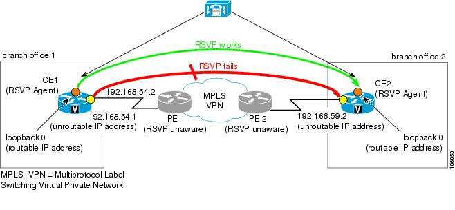
In the figure above, when a call is made from branch office 1 to branch office 2, the RSVP Agent on customer edge (CE)1 tries to set up a session with CE2 and sends a PATH message. CE1 stamps its outgoing interface IP address (192.168.54.1), which is an unroutable IP address, in the PHOP object of the PATH message. This PATH message is tunneled across the service provider network and processed by CE2. CE2 records this IP address in the PHOP object of the received PATH message in the PSB (Path State Block).
CE2 has a receiver proxy configured for the destination address of the session. As a result, when CE2 replies back with a RESV message, CE2 tries to send the RESV message to the IP address that CE2 had recorded in its PSB. Because this IP address (192.168.54.1) is unroutable from CE2, the RESV message will fail.
 Note | Once you configure a source address on an interface, RSVP always uses the RSVP-overwritten address rather than the native interface address. |
How to Configure RSVP-Previous Hop Overwrite
Configuring a Source Address or a Source Interface
DETAILED STEPS
Verifying the PHOP Configuration
DETAILED STEPS
| Command or Action | Purpose | |||
|---|---|---|---|---|
Step 1 |
enable
Example: Router> enable |
(Optional) Enables privileged EXEC mode.
| ||
Step 2 |
show
ip
rsvp
interface
[detail]
[interface-type interface-number]
Example: Router# show ip rsvp interface detail ethernet0/1 |
(Optional) Displays RSVP-related interface information. | ||
Step 3 |
exit
Example: Router# exit |
(Optional) Exits privileged EXEC mode and returns to user EXEC mode. |
Configuration Examples for RSVP-Previous Hop Overwrite
- Examples Configuring RSVP-Previous Hop Overwrite
- Examples Verifying RSVP-Previous Hop Overwrite Configuration
Examples Configuring RSVP-Previous Hop Overwrite
Configuring a Source Address on Router CE1 for the CE1-to-PE1 Interface
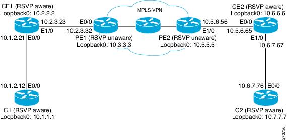
The following example configures a source address on the CE1-to-PE1 (Ethernet 1/0) interface in the figure above:
Router(CE1)# configure terminal

Enter configuration commands, one per line.  End with CNTL/Z.
Router(CE1)(config)# interface ethernet 1/0
Router(CE1)(config-if)# ip rsvp source address 10.2.2.2
 <--------------------
Router(CE1)(config-if)# end
Configuring a Source Address on Router CE2 for the CE2-to-PE2 Interface
The following example configures a source address on the CE2-to-PE2 (Ethernet 0/0) interface in the figure above:
Router(CE2)# configure terminal

Enter configuration commands, one per line.  End with CNTL/Z.
Router(CE2)(config)# interface ethernet 0/0
Router(CE2)(config-if)# ip rsvp source address 10.6.6.6
 <---------------------
Router(CE2)(config-if)# end
Creating a Listener Proxy on Router C2
The following example creates a listener proxy on Router C2 and requests that the receiver reply with a RESV message for the flow if the PATH message destination is 10.7.7.7 in the figure above:
Router(C2)# configure terminal
Enter configuration commands, one per line.  End with CNTL/Z.
Router(C2)(config)# ip rsvp listener 10.7.7.7 any any reply <--------------------
Router(C2)(config)# end
Creating a Session from Router C1 to Router C2
The following example creates an RSVP session from Router C1 to Router C2:
Router(C1)# configure terminal
Enter configuration commands, one per line.  End with CNTL/Z.
Router(C1)(config)# ip rsvp sender-host 10.7.7.7 10.1.1.1 UDP 100 200 1 1 <-------------
Router(C1)(config)# end
Examples Verifying RSVP-Previous Hop Overwrite Configuration
Verifying the Source Address on Router CE1 for the CE1-to-PE1 Interface
The following example verifies the source address (10.2.2.2) configured on the CE1-to-PE1 (Ethernet 1/0) interface in the figure below:
Router(CE1)# show ip rsvp interface detail ethernet 1/0
 Et1/0:
   RSVP: Enabled
   Interface State: Up
   Bandwidth:
     Curr allocated: 1K bits/sec
     Max. allowed (total): 100K bits/sec
     Max. allowed (per flow): 100K bits/sec
     Max. allowed for LSP tunnels using sub-pools: 0 bits/sec
     Set aside by policy (total): 0 bits/sec
   Admission Control:
     Header Compression methods supported:
       rtp (36 bytes-saved), udp (20 bytes-saved)
   Traffic Control:
     RSVP Data Packet Classification is ON via CEF callbacks
   Signalling:
     DSCP value used in RSVP msgs: 0x3F
     Number of refresh intervals to enforce blockade state: 4
     Ip address used in RSVP objects: 10.2.2.2 <------------------------------------
   Authentication: disabled
     Key chain:   <none>
     Type:        md5
     Window size: 1
     Challenge:   disabled
   Hello Extension:
     State: Disabled
Verifying the Source Address on Router CE2 for the CE2-to-PE2 Interface
The following example verifies the source address configured on the CE2-to-PE2 (Ethernet 0/0) interface in the figure below:
Router(CE2)# show ip rsvp interface detail ethernet 0/0
 Et0/0:
   RSVP: Enabled
   Interface State: Up
   Bandwidth:
     Curr allocated: 0 bits/sec
     Max. allowed (total): 100K bits/sec
     Max. allowed (per flow): 100K bits/sec
     Max. allowed for LSP tunnels using sub-pools: 0 bits/sec
     Set aside by policy (total): 0 bits/sec
   Admission Control:
     Header Compression methods supported:
       rtp (36 bytes-saved), udp (20 bytes-saved)
   Traffic Control:
     RSVP Data Packet Classification is ON via CEF callbacks
   Signalling:
     DSCP value used in RSVP msgs: 0x3F
     Number of refresh intervals to enforce blockade state: 4
     Ip address used in RSVP objects: 10.6.6.6 <-----------------------------------
   Authentication: disabled
     Key chain:   <none>
     Type:        md5
     Window size: 1
     Challenge:   disabled
   Hello Extension:
     State: Disabled
Verifying the Listener Proxy on Router C2
The following example verifies the listener proxy configured on Router C2 in the figure below:
Router(C2)# show ip rsvp listeners
To                Protocol   DPort   Description                 Action
10.7.7.7 <-------- any        any     RSVP Proxy                  reply
Verifying the Session from Router C1 to Router C2
The following example verifies that the session configured between Router C1 and Router C2 in the figure below is up:
Router(C1)# show ip rsvp reservation
To              From          Pro DPort Sport Next Hop      I/F      Fi Serv BPS
10.7.7.7       10.1.1.1       UDP 100   200   10.1.2.21     Et0/0    FF RATE 1K
Verifying the PHOP Address
The following example on Router CE2 verifies the source address configured on the CE1-to-PE1 interface in the figure below as the PHOP address:
Router(CE2)# show ip rsvp sender detail
PATH:
  Destination 10.7.7.7, Protocol_Id 17, Don't Police , DstPort 100
  Sender address: 10.1.1.1, port: 200
  Path refreshes:
    arriving: from PHOP 10.2.2.2 on Et0/0 every 30000 msecs <-------------------
  Traffic params - Rate: 1K bits/sec, Max. burst: 1K bytes
    Min Policed Unit: 0 bytes, Max Pkt Size 2147483647 bytes
  Path ID handle: CA000406.
  Incoming policy: Accepted. Policy source(s): Default
  Status:
  Output on Ethernet1/0. Policy status: Forwarding. Handle: 0E000402
    Policy source(s): Default
Verifying the Next-Hop Address
The following example on Router CE1 verifies the source address configured on the CE2-to-PE2 interface in the figure below as the next-hop address:
Router(CE1)# show ip rsvp reservation detail
RSVP Reservation. Destination is 10.7.7.7, Source is 10.1.1.1,
  Protocol is UDP, Destination port is 100, Source port is 200
  Next Hop: 10.6.6.6 on Ethernet1/0 <---------------------------------------------
  Reservation Style is Fixed-Filter, QoS Service is Guaranteed-Rate
  Resv ID handle: 03000400.
  Created: 07:01:40 IST Tue Mar 25 2008
  Average Bitrate is 1K bits/sec, Maximum Burst is 1K bytes
  Min Policed Unit: 0 bytes, Max Pkt Size: 0 bytes
  Status:
  Policy: Forwarding. Policy source(s): Default
Additional References
Related Documents
|
Related Topic |
Document Title |
|---|---|
|
Cisco IOS commands |
|
|
QoS commands: complete command syntax, command mode, command history, defaults, usage guidelines, and examples |
Cisco IOS Quality of Service Solutions Command Reference |
|
QoS features including signaling, classification, and congestion management |
"Quality of Service Overview" module |
MIBs
Technical Assistance
|
Description |
Link |
|---|---|
|
The Cisco Support and Documentation website provides online resources to download documentation, software, and tools. Use these resources to install and configure the software and to troubleshoot and resolve technical issues with Cisco products and technologies. Access to most tools on the Cisco Support and Documentation website requires a Cisco.com user ID and password. |
Feature Information for RSVP-Previous Hop Overwrite
The following table provides release information about the feature or features described in this module. This table lists only the software release that introduced support for a given feature in a given software release train. Unless noted otherwise, subsequent releases of that software release train also support that feature.
Use Cisco Feature Navigator to find information about platform support and Cisco software image support. To access Cisco Feature Navigator, go to www.cisco.com/go/cfn. An account on Cisco.com is not required.
| Table 1 | Feature Information for RSVP--Previous Hop Overwrite |
|
Feature Name |
Releases |
Feature Information |
|---|---|---|
|
RSVP--Previous Hop Overwrite |
12.4(20)T 15.0(1)SY |
The RSVP--Previous Hop Overwrite feature allows you to configure a Resource Reservation Protocol (RSVP) router, on a per interface basis, to populate an address other than the native interface address in the previous hop (PHOP) address field of the PHOP object when forwarding a PATH message onto that interface. You can configure the actual address for the router to use, or an interface, including a loopback, from which to borrow the address. The following commands were introduced or modified: debug ip rsvp, ip rsvp source, show ip rsvp interface. |
Glossary
QoS --quality of service. A measure of performance for a transmission system that reflects its transmission quality and service availability.
RSVP --Resource Reservation Protocol. A protocol that supports the reservation of resources across an IP network. Applications running on IP end systems can use RSVP to indicate to other nodes the nature (bandwidth, jitter, maximum burst, and so on) of the packet streams that they want to receive.
RSVP Agent --Implements a Resource Reservation Protocol (RSVP) agent on Cisco IOS voice gateways that support Unified CM.
Unified Communcations Manager (CM)--The software-based, call-processing component of the Cisco IP telephony solution. The software extends enterprise telephony features and functions to packet telephony network devices such as IP phones, media processing devices, voice-over-IP (VoIP) gateways, and multimedia applications.
Cisco and the Cisco Logo are trademarks of Cisco Systems, Inc. and/or its affiliates in the U.S. and other countries. A listing of Cisco's trademarks can be found at www.cisco.com/go/trademarks. Third party trademarks mentioned are the property of their respective owners. The use of the word partner does not imply a partnership relationship between Cisco and any other company. (1005R)
Any Internet Protocol (IP) addresses and phone numbers used in this document are not intended to be actual addresses and phone numbers. Any examples, command display output, network topology diagrams, and other figures included in the document are shown for illustrative purposes only. Any use of actual IP addresses or phone numbers in illustrative content is unintentional and coincidental.