
 Feedback
Contents
- Congestion Management Overview
- Finding Feature Information
- Why Use Congestion Management
- Deciding Which Queueing Policy to Use
- FIFO Queueing
- Weighted Fair Queueing
- Flow-Based Weighted Fair Queueing
- Restrictions
- WFQ and IP Precedence
- WFQ and RSVP
- Distributed Weighted Fair Queueing
- Drop Policy
- Restrictions
- Class-Based Weighted Fair Queueing
- CBWFQ Bandwidth Allocation
- Why Use CBWFQ
- CBWFQ and RSVP
- Restrictions
- Distributed Class-Based Weighted Fair Queueing
- RSVP Interaction with DCBWFQ
- Benefits
- Bandwidth Allocation
- Coarser Granularity and Scalability
- Restrictions
- Using the bandwidth Command on VIP Default Traffic Class
- Using the match protocol Command on a VIP
- PA-A3-8T1IMA Modules
- Prerequisites
- WFQ
- ACLs
- Modular QoS CLI
- IP RTP Priority
- IP RTP Priority Bandwidth Allocation
- Restrictions
- Frame Relay IP RTP Priority
- Frame Relay PVC Interface Priority Queueing
- Restrictions
- Prerequisites
- Low Latency Queueing
- LLQ Bandwidth Allocation
- LLQ with IP RTP Priority
- LLQ and Committed Burst Size
- LLQ and per-VC Hold Queue Support for ATM Adapters
- Why Use LLQ
- Restrictions
- Distributed Low Latency Queueing
- Guaranteeing Bandwidth with the priority Command
- Benefits
- Provides Priority Service on ATM VCs and Serial Interface
- Admission Control
- Limiting Particles on a Transmission Ring
- Restrictions
- Prerequisites
- Low Latency Queueing for Frame Relay
- Restrictions
- Prerequisites
- How It Works
- RTP Prioritization
- Voice over Frame Relay
- Frame Relay Fragmentation
- IP Cisco Express Forwarding Switching
- Custom Queueing
- How It Works
- Determining Byte Count Values for Queues
- How the Byte Count Is Used
- Determining the Byte Count
- Window Size
- Why Use CQ
- Restrictions
- Priority Queueing
- How It Works
- How Packets Are Classified for Priority Queueing
- Why Use Priority Queueing
- Restrictions
- Bandwidth Management
Congestion Management Overview
Congestion management features allow you to control congestion by determining the order in which packets are sent out an interface based on priorities assigned to those packets. Congestion management entails the creation of queues, assignment of packets to those queues based on the classification of the packet, and scheduling of the packets in a queue for transmission. The congestion management QoS feature offers four types of queueing protocols, each of which allows you to specify creation of a different number of queues, affording greater or lesser degrees of differentiation of traffic, and to specify the order in which that traffic is sent.
During periods with light traffic, that is, when no congestion exists, packets are sent out the interface as soon as they arrive. During periods of transmit congestion at the outgoing interface, packets arrive faster than the interface can send them. If you use congestion management features, packets accumulating at an interface are queued until the interface is free to send them; they are then scheduled for transmission according to their assigned priority and the queueing mechanism configured for the interface. The router determines the order of packet transmission by controlling which packets are placed in which queue and how queues are serviced with respect to each other.
This module discusses these four types of queueing, which constitute the congestion management QoS features:
- FIFO (first-in, first-out). FIFO entails no concept of priority or classes of traffic. With FIFO, transmission of packets out the interface occurs in the order the packets arrive.
- Weighted fair queueing (WFQ). WFQ offers dynamic, fair queueing that divides bandwidth across queues of traffic based on weights. (WFQ ensures that all traffic is treated fairly, given its weight.) To understand how WFQ works, consider the queue for a series of File Transfer Protocol (FTP) packets as a queue for the collective and the queue for discrete interactive traffic packets as a queue for the individual. Given the weight of the queues, WFQ ensures that for all FTP packets sent as a collective an equal number of individual interactive traffic packets are sent.)
Given this handling, WFQ ensures satisfactory response time to critical applications, such as interactive, transaction-based applications, that are intolerant of performance degradation. For serial interfaces at E1 (2.048 Mbps) and below, flow-based WFQ is used by default. When no other queueing strategies are configured, all other interfaces use FIFO by default.
There are four types of WFQ:
-
- Flow-based WFQ (WFQ)
- Distributed WFQ (DWFQ)
- Class-based WFQ (CBWFQ)
- Distributed class-based WFQ (DCBWFQ)
- Custom queueing (CQ). With CQ, bandwidth is allocated proportionally for each different class of traffic. CQ allows you to specify the number of bytes or packets to be drawn from the queue, which is especially useful on slow interfaces.
- Priority queueing (PQ). With PQ, packets belonging to one priority class of traffic are sent before all lower priority traffic to ensure timely delivery of those packets.
 Note | You can assign only one queueing mechanism type to an interface. |
Finding Feature Information
Your software release may not support all the features documented in this module. For the latest feature information and caveats, see the release notes for your platform and software release. To find information about the features documented in this module, and to see a list of the releases in which each feature is supported, see the Feature Information Table at the end of this document.
Use Cisco Feature Navigator to find information about platform support and Cisco software image support. To access Cisco Feature Navigator, go to www.cisco.com/go/cfn. An account on Cisco.com is not required.
Why Use Congestion Management
Heterogeneous networks include many different protocols used by applications, giving rise to the need to prioritize traffic in order to satisfy time-critical applications while still addressing the needs of less time-dependent applications, such as file transfer. Different types of traffic sharing a data path through the network can interact with one another in ways that affect their application performance. If your network is designed to support different traffic types that share a single data path between routers, you should consider using congestion management techniques to ensure fairness of treatment across the various traffic types.
Here are some broad factors to consider in determining whether to configure congestion management QoS:
- Traffic prioritization is especially important for delay-sensitive, interactive transaction-based applications--for instance, desktop video conferencing--that require higher priority than do file transfer applications. However, use of WFQ ensures that all traffic is treated fairly, given its weight, and in a dynamic manner. For example, WFQ addresses the requirements of the interactive application without penalizing the FTP application.
- Prioritization is most effective on WAN links where the combination of bursty traffic and relatively lower data rates can cause temporary congestion.
- Depending on the average packet size, prioritization is most effective when applied to links at T1/E1 bandwidth speeds or lower.
- If users of applications running across your network notice poor response time, you should consider using congestion management features. Congestion management features are dynamic, tailoring themselves to the existing network conditions. However, consider that if a WAN link is constantly congested, traffic prioritization may not resolve the problem. Adding bandwidth might be the appropriate solution.
- If there is no congestion on the WAN link, there is no reason to implement traffic prioritization.
The following list summarizes aspects you should consider in determining whether you should establish and implement a queueing policy for your network:
- Determine if the WAN is congested--that is, whether users of certain applications perceive a performance degradation.
- Determine your goals and objectives based on the mix of traffic you need to manage and your network topology and design. In identifying what you want to achieve, consider whether your goal is among the following:
- To establish fair distribution of bandwidth allocation across all of the types of traffic you identify.
- To grant strict priority to traffic from special kinds of applications you service--for example, interactive multimedia applications--possibly at the expense of less-critical traffic you also support.
- To customize bandwidth allocation so that network resources are shared among all of the applications you service, each having the specific bandwidth requirements you have identified.
- To effectively configure queueing. You must analyze the types of traffic using the interface and determine how to distinguish them. See the "Classification Overview" module for a description of how packets are classified.
After you assess your needs, review the available congestion management queueing mechanisms described in this module and determine which approach best addresses your requirements and goals.
Traffic patterns change over time, so you should repeat the analysis process described in the second bullet periodically, and adapt the queueing configuration accordingly.
See the following section Deciding Which Queueing Policy to Use for elaboration of the differences among the various queueing mechanisms.
Deciding Which Queueing Policy to Use
This section looks briefly at some of the differences between the types of queueing and includes a table that compares the main queueing strategies.
FIFO queueing performs no prioritization of data packets on user data traffic. It entails no concept of priority or classes of traffic. When FIFO is used, ill-behaved sources can consume available bandwidth, bursty sources can cause delays in time-sensitive or important traffic, and important traffic may be dropped because less important traffic fills the queue.
Consider these differences in deciding whether to use CQ or PQ:
- CQ guarantees some level of service to all traffic because you can allocate bandwidth to all classes of traffic. You can define the size of the queue by determining its configured packet-count capacity, thereby controlling bandwidth access.
- PQ guarantees strict priority in that it ensures that one type of traffic will be sent, possibly at the expense of all others. For PQ, a low priority queue can be detrimentally affected, and, in the worst case, never allowed to send its packets if a limited amount of bandwidth is available or if the transmission rate of critical traffic is high.
In deciding whether to use WFQ or one of the other two queueing types, consider these differences among WFQ and PQ and CQ:
- WFQ does not require configuration of access lists to determine the preferred traffic on a serial interface. Rather, the fair queue algorithm dynamically sorts traffic into messages that are part of a conversation.
- Low-volume, interactive traffic gets fair allocation of bandwidth with WFQ, as does high-volume traffic such as file transfers.
- Strict priority queueing can be accomplished with WFQ by using the IP RTP Priority, Frame Relay IP RTP Priority, low latency queueing (LLQ), distributed low latency queueing, low latency queueing for Frame Relay, or Frame Relay PVC Interface Priority Queueing features. Strict PQ allows delay-sensitive data such as voice to be dequeued and sent before packets in other queues are dequeued.
The table below compares the salient features of flow-based WFQ, CBWFQ and DCBWFQ, CQ, and PQ.
| Table 1 | Queueing Comparison |
FIFO Queueing
In its simplest form, FIFO queueing--also known as first-come, first-served (FCFS) queueing--involves buffering and forwarding of packets in the order of arrival.
FIFO embodies no concept of priority or classes of traffic and consequently makes no decision about packet priority. There is only one queue, and all packets are treated equally. Packets are sent out an interface in the order in which they arrive.
When FIFO is used, ill-behaved sources can consume all the bandwidth, bursty sources can cause delays in time-sensitive or important traffic, and important traffic can be dropped because less important traffic fills the queue.
When no other queueing strategies are configured, all interfaces except serial interfaces at E1 (2.048 Mbps) and below use FIFO by default. (Serial interfaces at E1 and below use WFQ by default.)
FIFO, which is the fastest method of queueing, is effective for large links that have little delay and minimal congestion. If your link has very little congestion, FIFO queueing may be the only queueing you need to use.
Weighted Fair Queueing
This section discusses the four types of WFQ described in the following sections:
- Flow-Based Weighted Fair Queueing
- Distributed Weighted Fair Queueing
- Class-Based Weighted Fair Queueing
- Distributed Class-Based Weighted Fair Queueing
This section also discusses the six related features described in the following sections:
- IP RTP Priority
- Frame Relay IP RTP Priority
- Frame Relay PVC Interface Priority Queueing
- Low Latency Queueing
- Distributed Low Latency Queueing
- Low Latency Queueing for Frame Relay
The table below summarizes the differences among WFQ, DWFQ, CBWFQ, and DCBWFQ.
| Table 2 | WFQ, DWFQ, CBWFQ, and DCBWFQ Comparison |
For DWFQ and DCBWFQ, all queueing is transacted by the VIP. On the VIP, all packets are sent directly out the interface. A Route Switch Processor (RSP) resides on the same platform as the VIP. The RSP handles all tasks associated with system maintenance and routing. The VIP and the RSP each handle some scheduling. The dual-processor support accounts for the faster speed of DWFQ and DCBWFQ over WFQ running on standard Cisco IOS platforms.
For information on how to configure WFQ, DWFQ, CBWFQ, and DCBWFQ, see the "Configuring Weighted Fair Queueing" module. For information on how to configure per-VC WFQ and CBWFQ, see the "Configuring IP to ATM Class of Service" module.
- Flow-Based Weighted Fair Queueing
- Distributed Weighted Fair Queueing
- Class-Based Weighted Fair Queueing
- Distributed Class-Based Weighted Fair Queueing
- IP RTP Priority
- Frame Relay IP RTP Priority
- Frame Relay PVC Interface Priority Queueing
- Low Latency Queueing
- Distributed Low Latency Queueing
- Low Latency Queueing for Frame Relay
Flow-Based Weighted Fair Queueing
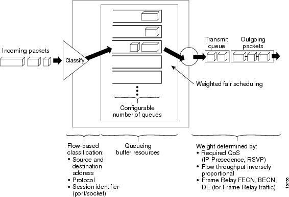
WFQ is a dynamic scheduling method that provides fair bandwidth allocation to all network traffic. WFQ applies priority, or weights, to identified traffic to classify traffic into conversations and determine how much bandwidth each conversation is allowed relative to other conversations. WFQ is a flow-based algorithm that simultaneously schedules interactive traffic to the front of a queue to reduce response time and fairly shares the remaining bandwidth among high-bandwidth flows. In other words, WFQ allows you to give low-volume traffic, such as Telnet sessions, priority over high-volume traffic, such as FTP sessions. WFQ gives concurrent file transfers balanced use of link capacity; that is, when multiple file transfers occur, the transfers are given comparable bandwidth. The figure below shows how WFQ works.
WFQ overcomes a serious limitation of FIFO queueing. When FIFO is in effect, traffic is sent in the order received without regard for bandwidth consumption or the associated delays. As a result, file transfers and other high-volume network applications often generate series of packets of associated data. These related packets are known as packet trains. Packet trains are groups of packets that tend to move together through the network. These packet trains can consume all available bandwidth, depriving other traffic of bandwidth.
WFQ provides traffic priority management that dynamically sorts traffic into messages that make up a conversation. WFQ breaks up the train of packets within a conversation to ensure that bandwidth is shared fairly between individual conversations and that low-volume traffic is transferred in a timely fashion.
WFQ classifies traffic into different flows based on packet header addressing, including such characteristics as source and destination network or MAC address, protocol, source and destination port and socket numbers of the session, Frame Relay data-link connection identifier (DLCI) value, and ToS value. There are two categories of flows: high-bandwidth sessions and low-bandwidth sessions. Low-bandwidth traffic has effective priority over high-bandwidth traffic, and high-bandwidth traffic shares the transmission service proportionally according to assigned weights. Low-bandwidth traffic streams, which comprise the majority of traffic, receive preferential service, allowing their entire offered loads to be sent in a timely fashion. High-volume traffic streams share the remaining capacity proportionally among themselves.
WFQ places packets of the various conversations in the fair queues before transmission. The order of removal from the fair queues is determined by the virtual time of the delivery of the last bit of each arriving packet.
New messages for high-bandwidth flows are discarded after the congestive-messages threshold has been met. However, low-bandwidth flows, which include control-message conversations, continue to enqueue data. As a result, the fair queue may occasionally contain more messages than are specified by the threshold number.
WFQ can manage duplex data streams, such as those between pairs of applications, and simplex data streams such as voice or video.
The WFQ algorithm also addresses the problem of round-trip delay variability. If multiple high-volume conversations are active, their transfer rates and interarrival periods are made much more predictable. WFQ greatly enhances algorithms such as Systems Network Architecture (SNA) Logical Link Control (LLC) and TCP congestion control and slow start features.
Flow-based WFQ is used as the default queueing mode on most serial interfaces configured to run at E1 speeds (2.048 Mbps) or below.
WFQ provides the solution for situations in which it is desirable to provide consistent response time to heavy and light network users alike without adding excessive bandwidth. WFQ automatically adapts to changing network traffic conditions.
Restrictions
WFQ is not supported with tunneling and encryption because these features modify the packet content information required by WFQ for classification.
Although WFQ automatically adapts to changing network traffic conditions, it does not offer the degree of precision control over bandwidth allocation that CQ and CBWFQ offer.
WFQ and IP Precedence
WFQ is IP precedence-aware. It can detect higher priority packets marked with precedence by the IP Forwarder and can schedule them faster, providing superior response time for this traffic. Thus, as the precedence increases, WFQ allocates more bandwidth to the conversation during periods of congestion.
WFQ assigns a weight to each flow, which determines the transmit order for queued packets. In this scheme, lower weights are served first. For standard Cisco IOS WFQ, the IP precedence serves as a divisor to this weighting factor.
Like CQ, WFQ sends a certain number of bytes from each queue. With WFQ, each queue corresponds to a different flow. For each cycle through all flows, WFQ effectively sends a number of bytes equal to the precedence of the flow plus one. This number is only used as a ratio to determine how many bytes per packets to send. However, for the purposes of understanding WFQ, using this number as the byte count is sufficient. For instance, traffic with an IP Precedence value of 7 gets a lower weight than traffic with an IP Precedence value of 3, thus, the priority in transmit order. The weights are inversely proportional to the IP Precedence value.
To determine the bandwidth allocation for each queue, divide the byte count for the flow by the total byte count for all flows. For example, if you have one flow at each precedence level, each flow will get precedence + 1 parts of the link:
1 + 2 + 3 + 4 + 5 + 6 + 7 + 8 = 36
Thus, precedence 0 traffic will get 1/36 of the bandwidth, precedence 1 traffic will get 2/36, and precedence 7 traffic will get 8/36.
However, if you have 18 precedence 1 flows and one of each of the rest, the total is now:
1 + 2(18) + 3 + 4 + 5 + 6 + 7 + 8 = 70
Precedence 0 traffic will get 1/70, each of the precedence 1 flows will get 2/70, and so on.
As flows are added or ended, the actual allocated bandwidth will continuously change.
WFQ and RSVP
RSVP uses WFQ to allocate buffer space and schedule packets, and to guarantee bandwidth for reserved flows. WFQ works with RSVP to help provide differentiated and guaranteed QoS services.
RSVP is the Internet Engineering Task Force (IETF) Internet Standard (RFC 2205) protocol for allowing an application to dynamically reserve network bandwidth. RSVP enables applications to request a specific QoS for a data flow. The Cisco implementation allows RSVP to be initiated within the network using configured proxy RSVP.
RSVP is the only standard signalling protocol designed to guarantee network bandwidth from end to end for IP networks. Hosts and routers use RSVP to deliver QoS requests to the routers along the paths of the data stream and to maintain router and host state to provide the requested service, usually bandwidth and latency. RSVP uses a mean data rate, the largest amount of data the router will keep in queue, and minimum QoS to determine bandwidth reservation.
WFQ or Weighted Random Early Detection (WRED) acts as the preparer for RSVP, setting up the packet classification and scheduling required for the reserved flows. Using WFQ, RSVP can deliver an Integrated Services Guaranteed Service.
Distributed Weighted Fair Queueing
DWFQ is a special high-speed version of WFQ that runs on the VIP. It is supported on the following routers with a VIP2-40 or greater interface processor:
A VIP2-50 interface processor is recommended when the aggregate line rate of the port adapters on the VIP is greater than DS3. A VIP2-50 card is required for OC-3 rates.
To use DWFQ, distributed Cisco Express Forwarding (dCEF) switching must be enabled on the interface.
Note | The VIP-distributed WFQ implementation differs from WFQ that runs on all other platforms. |
There are two forms of distributed WFQ:
- Flow-based. In this form, packets are classified by flow. Packets with the same source IP address, destination IP address, source TCP or User Datagram Protocol (UDP) port, destination TCP or UDP port, protocol, and ToS field belong to the same flow. (All non-IP packets are treated as flow 0.)
Each flow corresponds to a separate output queue. When a packet is assigned to a flow, it is placed in the queue for that flow. During periods of congestion, DWFQ allocates an equal share of the bandwidth to each active queue.
Flow-based DWFQ is also called fair queueing because all flows are equally weighted and allocated equal bandwidth. In the current implementation of DWFQ, weights are not assigned to flows. With DWFQ, well-behaved hosts are protected from ill-behaved hosts.
- Class-based. In this form, packets are assigned to different queues based on their QoS group or the IP precedence in the ToS field.
QoS groups allow you to customize your QoS policy. A QoS group is an internal classification of packets used by the router to determine how packets are treated by certain QoS features, such as DWFQ and committed access rate (CAR). Use a CAR policy or the QoS Policy Propagation via Border Gateway Protocol (BGP) feature to assign packets to QoS groups.
If you want to classify packets based only on the two low-order IP Precedence bits, use ToS-based DWFQ. Specify a weight for each class. In periods of congestion, each group is allocated a percentage of the output bandwidth equal to the weight of the class. For example, if a class is assigned a weight of 50, packets from this class will be allocated at least 50 percent of the outgoing bandwidth during periods of congestion. When the interface is not congested, queues can use any available bandwidth.
The "Drop Policy" section describes the drop policy used by both forms.
Drop Policy
DWFQ keeps track of the number of packets in each queue and the total number of packets in all queues.
When the total number of packets is below the aggregate limit, queues can buffer more packets than the individual queue limit.
When the total number of packets reaches the aggregate limit, the interface starts enforcing the individual queue limits. Any new packets that arrive for a queue that has exceeded its individual queue limit are dropped. Packets that are already in the queue will not be dropped, even if the queue is over the individual limit.
In some cases, the total number of packets in all queues put together may exceed the aggregate limit.
Restrictions
Use DWFQ with IP traffic. All non-IP traffic is treated as a single flow and, therefore, placed in the same queue.
DWFQ has the following restrictions:
- Can be configured on interfaces, but not subinterfaces.
- Is not supported with the ATM encapsulations AAL5-MUX and AAL5-NLPID.
- Is not supported on Fast EtherChannel, tunnel interfaces, or other logical (virtual) interfaces such as Multilink PPP (MLP).
- Cannot be configured on the same interface as RSP-based PQ, CQ, or WFQ.
Class-Based Weighted Fair Queueing
CBWFQ extends the standard WFQ functionality to provide support for user-defined traffic classes. For CBWFQ, you define traffic classes based on match criteria including protocols, access control lists (ACLs), and input interfaces. Packets satisfying the match criteria for a class constitute the traffic for that class. A FIFO queue is reserved for each class, and traffic belonging to a class is directed to the queue for that class.
Once a class has been defined according to its match criteria, you can assign it characteristics. To characterize a class, you assign it bandwidth, weight, and maximum packet limit. The bandwidth assigned to a class is the guaranteed bandwidth delivered to the class during congestion.
To characterize a class, you also specify the queue limit for that class, which is the maximum number of packets allowed to accumulate in the queue for the class. Packets belonging to a class are subject to the bandwidth and queue limits that characterize the class.
After a queue has reached its configured queue limit, enqueueing of additional packets to the class causes tail drop or packet drop to take effect, depending on how class policy is configured.
Tail drop is used for CBWFQ classes unless you explicitly configure policy for a class to use WRED to drop packets as a means of avoiding congestion. Note that if you use WRED packet drop instead of tail drop for one or more classes comprising a policy map, you must ensure that WRED is not configured for the interface to which you attach that service policy.
If a default class is configured with the bandwidth policy-map class configuration command, all unclassified traffic is put into a single FIFO queue and given treatment according to the configured bandwidth. If a default class is configured with the fair-queue command, all unclassified traffic is flow classified and given best-effort treatment. If no default class is configured, then by default the traffic that does not match any of the configured classes is flow classified and given best-effort treatment. Once a packet is classified, all of the standard mechanisms that can be used to differentiate service among the classes apply.
Flow classification is standard WFQ treatment. That is, packets with the same source IP address, destination IP address, source TCP or UDP port, or destination TCP or UDP port are classified as belonging to the same flow. WFQ allocates an equal share of bandwidth to each flow. Flow-based WFQ is also called fair queueing because all flows are equally weighted.
For CBWFQ, the weight specified for the class becomes the weight of each packet that meets the match criteria of the class. Packets that arrive at the output interface are classified according to the match criteria filters you define, then each one is assigned the appropriate weight. The weight for a packet belonging to a specific class is derived from the bandwidth you assigned to the class when you configured it; in this sense the weight for a class is user-configurable.
After the weight for a packet is assigned, the packet is enqueued in the appropriate class queue. CBWFQ uses the weights assigned to the queued packets to ensure that the class queue is serviced fairly.
Configuring a class policy--thus, configuring CBWFQ--entails these three processes:
- Defining traffic classes to specify the classification policy (class maps).
This process determines how many types of packets are to be differentiated from one another.
- Associating policies--that is, class characteristics--with each traffic class (policy maps).
This process entails configuration of policies to be applied to packets belonging to one of the classes previously defined through a class map. For this process, you configure a policy map that specifies the policy for each traffic class.
- Attaching policies to interfaces (service policies).
This process requires that you associate an existing policy map, or service policy, with an interface to apply the particular set of policies for the map to that interface.
CBWFQ Bandwidth Allocation
The sum of all bandwidth allocation on an interface cannot exceed 75 percent of the total available interface bandwidth. The remaining 25 percent is used for other overhead, including Layer 2 overhead, routing traffic, and best-effort traffic. Bandwidth for the CBWFQ class-default class, for instance, is taken from the remaining 25 percent. However, under aggressive circumstances in which you want to configure more than 75 percent of the interface bandwidth to classes, you can override the 75 percent maximum sum allocated to all classes or flows. If you want to override the default 75 percent, exercise caution and ensure that you allow enough remaining bandwidth to support best-effort and control traffic, and Layer 2 overhead.
When ATM is used you must account for the fact that ATM cell tax overhead is not included. For example, consider the case where a class needs guaranteed bandwidth on an ATM permanent virtual circuit (PVC). Suppose the average packet size for the class is 256 bytes and the class needs 100 kbps (which translates to 49 packets per second) of guaranteed bandwidth. Each 256-byte packet would be split into six cells to be sent on a VC, giving a total of 6 * 53 = 318 bytes. In this case, the ATM cell tax overhead would be 62 bytes or 49 * 62 * 8 = 24.34 kbps. When configuring CBWFQ in this example, ensure that the sum of all the configured class bandwidths is less than the VC bandwidth by at least 24.34 kbps to ensure desired payload guarantee for the configured classes (in this example, there is only one class). If you have several classes, the sum of all the class overheads should be estimated and added to the sum of all the configured class bandwidths. This total should be less than the VC bandwidth to ensure the required payload guarantees.
Why Use CBWFQ
Here are some general factors you should consider in determining whether you need to configure CBWFQ:
- Bandwidth allocation. CBWFQ allows you to specify the exact amount of bandwidth to be allocated for a specific class of traffic. Taking into account available bandwidth on the interface, you can configure up to 64 classes and control distribution among them, which is not the case with flow-based WFQ. Flow-based WFQ applies weights to traffic to classify it into conversations and determine how much bandwidth each conversation is allowed relative to other conversations. For flow-based WFQ, these weights, and traffic classification, are dependent on and limited to the seven IP Precedence levels.
- Coarser granularity and scalability. CBWFQ allows you to define what constitutes a class based on criteria that exceed the confines of flow. CBWFQ allows you to use ACLs and protocols or input interface names to define how traffic will be classified, thereby providing coarser granularity. You need not maintain traffic classification on a flow basis. Moreover, you can configure up to 64 discrete classes in a service policy.
CBWFQ and RSVP
RSVP can be used in conjunction with CBWFQ. When both RSVP and CBWFQ are configured for an interface, RSVP and CBWFQ act independently, exhibiting the same behavior that they would if each were running alone. RSVP continues to work as it does when CBWFQ is not present, even in regard to bandwidth availability assessment and allocation.
Restrictions
Configuring CBWFQ on a physical interface is only possible if the interface is in the default queueing mode. Serial interfaces at E1 (2.048 Mbps) and below use WFQ by default--other interfaces use FIFO by default. Enabling CBWFQ on a physical interface overrides the default interface queueing method. Enabling CBWFQ on an ATM PVC does not override the default queueing method.
If you configure a class in a policy map to use WRED for packet drop instead of tail drop, you must ensure that WRED is not configured on the interface to which you intend to attach that service policy.
Traffic shaping and policing are not currently supported with CBWFQ.
CBWFQ is supported on variable bit rate (VBR) and available bit rate (ABR) ATM connections. It is not supported on unspecified bit rate (UBR) connections.
CBWFQ is not supported on Ethernet subinterfaces.
Distributed Class-Based Weighted Fair Queueing
As explained earlier, WFQ offers dynamic, fair queueing that divides bandwidth across queues of traffic based on weights. WFQ ensures that all traffic is treated fairly, given its weight. For more information about WFQ, see the Weighted Fair Queueing section of this module.
The DCBWFQ feature extends the standard WFQ functionality to provide support for user-defined traffic classes on the VIP. These user-defined traffic classes are configured in the Modular Quality of Service Command-Line Interface (Modular QoS CLI) feature. For information on how to configure QoS with the Modular QoS CLI, see the "Applying QoS Features Using the MQC" module.
The maximum number of packets allowed to accumulate in a traffic class queue is called the queue limit and is specified with the queue-limit command when you create a service policy with the policy-map command. Packets belonging to a traffic class are subject to the guaranteed bandwidth allocation and the queue limits that characterize the traffic class.
After a queue has reached its configured queue limit, enqueuing of additional packets to the traffic class causes tail drop or WRED drop to take effect, depending on how the service policy is configured. (Tail drop is a means of avoiding congestion that treats all traffic equally and does not differentiate between classes of service. Queues fill during periods of congestion. When the output queue is full and tail drop is in effect, packets are dropped until the congestion is eliminated and the queue is no longer full).
Tail drop is used for DCBWFQ traffic classes unless you explicitly configure a service policy to use WRED to drop packets as a means of avoiding congestion. Note that if you use WRED packet drop instead of tail drop for one or more traffic classes making up a service policy, you must ensure that WRED is not configured for the interface to which you attach that service policy.
For information on how to configure DCBWFQ, see the "Configuring Weighted Fair Queueing" module.
RSVP Interaction with DCBWFQ
When RSVP and DCBWFQ are configured, RSVP and DCBWFQ act independently of one another. RSVP and DCBWFQ allocate bandwidth among their traffic classes and flows according to unallocated bandwidth available at the underlying point of congestion.
When an RSVP flow is created, the VIP queueing system reserves the unit of bandwidth allocation in an RSVP queue, similar to the way a traffic class queue is allotted to a DCBWFQ traffic class. DCBWFQ traffic classes are unaffected by the RSVP flows.
Benefits
Bandwidth Allocation
DCBWFQ allows you to specify the amount of guaranteed bandwidth to be allocated for a traffic class. Taking into account available bandwidth on the interface, you can configure up to 64 traffic classes and control bandwidth allocation among them. If excess bandwidth is available, the excess bandwidth is divided among the traffic classes in proportion to their configured bandwidths.
Flow-based WFQ allocates bandwidth equally among all flows.
Coarser Granularity and Scalability
DCBWFQ allows you to define what constitutes a traffic class based on criteria that exceed the confines of flow. DCBWFQ allows you to use ACLs and protocols or input interface names to define how traffic is classified, thereby providing coarser granularity. You need not maintain traffic classification on a flow basis. Moreover, you can configure up to 64 discrete traffic classes in a service policy.
Restrictions
- Using the bandwidth Command on VIP Default Traffic Class
- Using the match protocol Command on a VIP
- PA-A3-8T1IMA Modules
Using the bandwidth Command on VIP Default Traffic Class
On a VIP, all traffic that does not match a user-defined traffic class is classified as part of the default traffic class. The implicit bandwidth allocated to the default traffic class on a VIP is equal to the link bandwidth minus all of the user-defined bandwidth given to the user-defined traffic classes (with the bandwidth command). At least 1 percent of the link bandwidth is always reserved for the default traffic class.
Because the bandwidth of the default traffic class for a VIP is implicit (the default traffic class receives all remaining bandwidth not given to the user-defined traffic classes), the bandwidth command cannot be used with the default traffic class when you configure a VIP.
Prerequisites
WFQ
Attaching a service policy to an interface disables WFQ on that interface if WFQ is configured for the interface. For this reason, you should ensure that WFQ is not enabled on such an interface.
For information on WFQ, see the "Configuring Weighted Fair Queueing" module.
IP RTP Priority
The IP RTP Priority feature provides a strict priority queueing scheme for delay-sensitive data such as voice. Voice traffic can be identified by its Real-Time Transport Protocol (RTP) port numbers and classified into a priority queue configured by the ip rtp priority command. The result is that voice is serviced as strict priority in preference to other nonvoice traffic.
Note | Although this section focuses mainly on voice traffic, IP RTP Priority is useful for any RTP traffic. |
The IP RTP Priority feature extends and improves on the functionality offered by the ip rtp reserve command by allowing you to specify a range of UDP/RTP ports whose traffic is guaranteed strict priority service over any other queues or classes using the same output interface. Strict priority means that if packets exist in the priority queue, they are dequeued and before packets in other queues are dequeued. We recommend that you use the ip rtp priority command instead of the ip rtp reserve command for voice configurations.
The IP RTP Priority feature does not require that you know the port of a voice call. Rather, the feature gives you the ability to identify a range of ports whose traffic is put into the priority queue. Moreover, you can specify the entire voice port range--16384 to 32767--to ensure that all voice traffic is given strict priority service. IP RTP Priority is especially useful on links whose speed is less than 1.544 Mbps.
This feature can be used in conjunction with either WFQ or CBWFQ on the same outgoing interface. In either case, traffic matching the range of ports specified for the priority queue is guaranteed strict priority over other CBWFQ classes or WFQ flows; packets in the priority queue are always serviced first. Note the following conditions of the ip rtp priority command:
- When used in conjunction with WFQ, the ip rtp priority command provides strict priority to voice, and WFQ scheduling is applied to the remaining queues.
- When used in conjunction with CBWFQ, the ip rtp priority command provides strict priority to voice. CBWFQ can be used to set up classes for other types of traffic (such as SNA) that needs dedicated bandwidth and needs to be treated better than best effort and not as strict priority; the nonvoice traffic is serviced fairly based on the weights assigned to the enqueued packets. CBWFQ can also support flow-based WFQ within the default CBWFQ class if so configured.
Because voice packets are small in size and the interface also can have large packets going out, the Link Fragmentation and Interleaving (LFI) feature should also be configured on lower speed interfaces. When you enable LFI, the large data packets are broken up so that the small voice packets can be interleaved between the data fragments that make up a large data packet. LFI prevents a voice packet from needing to wait until a large packet is sent. Instead, the voice packet can be sent in a shorter amount of time.
For information on how to configure IP RTP Priority, see the "Configuring Weighted Fair Queueing" module.
IP RTP Priority Bandwidth Allocation
If you want to understand its behavior and properly use the IP RTP Priority feature, it is important to consider its admission control and policing characteristics. When you use the ip rtp priority command to configure the priority queue for voice, you specify a strict bandwidth limitation. This amount of bandwidth is guaranteed to voice traffic enqueued in the priority queue. (This is the case whether you use the IP RTP Priority feature with CBWFQ or WFQ.)
IP RTP Priority closely polices use of bandwidth for the priority queue, ensuring that the allocated amount is not exceeded in the event of congestion. In fact, IP RTP Priority polices the flow every second. IP RTP Priority prohibits transmission of additional packets once the allocated bandwidth is consumed. If it discovers that the configured amount of bandwidth is exceeded, IP RTP Priority drops packets, an event that is poorly tolerated by voice traffic. (Enable debugging to watch for this condition.) Close policing allows for fair treatment of other data packets enqueued in other CBWFQ or WFQ queues. To avoid packet drop, be certain to allocate to the priority queue the most optimum amount of bandwidth, taking into consideration the type of codec used and interface characteristics. IP RTP Priority will not allow traffic beyond the allocated amount.
It is always safest to allocate to the priority queue slightly more than the known required amount of bandwidth. For example, suppose you allocated 24 kbps bandwidth, the standard amount required for voice transmission, to the priority queue. This allocation seems safe because transmission of voice packets occurs at a constant bit rate. However, because the network and the router or switch can use some of the bandwidth and introduce jitter and delay, allocating slightly more than the required amount of bandwidth (such as 25 kbps) ensures constancy and availability.
The IP RTP Priority admission control policy takes RTP header compression into account. Therefore, while configuring the bandwidth parameter of the ip rtp priority command you only need to configure for the bandwidth of the compressed call. For example, if a G.729 voice call requires 24 kbps uncompressed bandwidth (not including Layer 2 payload) but only 12 kbps compressed bandwidth, you only need to configure a bandwidth of 12 kbps. You need to allocate enough bandwidth for all calls if there will be more than one call.
The sum of all bandwidth allocation for voice and data flows on the interface cannot exceed 75 percent of the total available bandwidth. Bandwidth allocation for voice packets takes into account the payload plus the IP, RTP, and UDP headers, but again, not the Layer 2 header. Allowing 25 percent bandwidth for other overhead is conservative and safe. On a PPP link, for instance, overhead for Layer 2 headers assumes 4 kbps.
If you know how much bandwidth is required for additional overhead on a link, under aggressive circumstances in which you want to give voice traffic as much bandwidth as possible, you can override the 75 percent maximum allocation for the bandwidth sum allocated to all classes or flows. If you want to override the fixed amount of bandwidth, exercise caution and ensure that you allow enough remaining bandwidth to support best-effort and control traffic, and Layer 2 overhead.
As another alternative, if the importance of voice traffic far exceeds that of data, you can allocate most of the 75 percent bandwidth used for flows and classes to the voice priority queue. Unused bandwidth at any given point will be made available to the other flows or classes.
Restrictions
Because the ip rtp priority command gives absolute priority over other traffic, it should be used with care. In the event of congestion, if the traffic exceeds the configured bandwidth, then all the excess traffic is dropped.
The ip rtp reserve and ip rtp priority commands cannot be configured on the same interface.
Frame Relay IP RTP Priority
The Frame Relay IP RTP Priority feature provides a strict priority queueing scheme on a Frame Relay PVC for delay-sensitive data such as voice. Voice traffic can be identified by its RTP port numbers and classified into a priority queue configured by the frame-relay ip rtp prioritycommand. The result of using this feature is that voice is serviced as strict priority in preference to other nonvoice traffic.
This feature extends the functionality offered by the ip rtp priority command by supporting Frame Relay PVCs. This feature allows you to specify a range of UDP ports whose voice traffic is guaranteed strict priority service over any other queues or classes using the same output interface. Strict priority means that if packets exist in the priority queue, they are dequeued and sent before packets in other queues are dequeued. This process is performed on a per-PVC basis, rather than at the interface level.
For information on how to configure Frame Relay IP RTP Priority, see the "Configuring Weighted Fair Queueing" module.
Frame Relay PVC Interface Priority Queueing
The Frame Relay PVC Interface Priority Queueing (PIPQ) feature provides an interface-level priority queueing scheme in which prioritization is based on destination PVC rather than packet contents. For example, Frame Relay (FR) PIPQ allows you to configure a PVC transporting voice traffic to have absolute priority over a PVC transporting signalling traffic, and a PVC transporting signalling traffic to have absolute priority over a PVC transporting data.
For information on how to configure Frame Relay PIPQ, see the "Configuring Weighted Fair Queueing" module. For information about Frame Relay, see the "Configuring Frame Relay" module.
Frame Relay PIPQ provides four levels of priority: high, medium, normal, and low. The Frame Relay packet is examined at the interface for the data-link connection identifier (DLCI) value. The packet is then sent to the correct priority queue based on the priority level configured for that DLCI.
You assign priority to a PVC within a Frame Relay map class. All PVCs using or inheriting that map class will be classed according to the configured priority. If a PVC does not have a map class associated with it, or if the map class associated with it does not have priority explicitly configured, then the packets on that PVC will be queued on the default "normal" priority queue.
If you do not enable Frame Relay PIPQ on the interface using the frame-relay interface-queue prioritycommand in interface configuration mode, configuring PVC priority within a map class will not be effective. At this time you have the option to also set the size (in maximum number of packets) of the four priority queues.
Frame Relay PIPQ works with or without Frame Relay Traffic Shaping (FRTS) and FRF.12 (or higher). The interface-level priority queueing takes the place of the FIFO queueing or dual FIFO queueing normally used by FRTS and FRF.12 (or higher). PVC priority assigned within FR PIPQ takes precedence over FRF.12 priority, which means that all packets destined for the same PVC will be queued on the same interface queue whether they were fragmented or not.
Restrictions
The following restrictions apply to Frame Relay PIPQ:
- It is not supported on loopback or tunnel interfaces, or interfaces that explicitly disallow priority queueing.
- It is not supported with hardware compression.
- It cannot be enabled on an interface that is already configured with queueing other than FIFO queueing. FR PIPQ can be enabled if WFQ is configured, as long as WFQ is the default interface queueing method.
Low Latency Queueing
The LLQ feature brings strict PQ to CBWFQ. Strict PQ allows delay-sensitive data such as voice to be dequeued and sent before packets in other queues are dequeued.
Without LLQ, CBWFQ provides WFQ based on defined classes with no strict priority queue available for real-time traffic. CBWFQ allows you to define traffic classes and then assign characteristics to that class. For example, you can designate the minimum bandwidth delivered to the class during congestion.
For CBWFQ, the weight for a packet belonging to a specific class is derived from the bandwidth you assigned to the class when you configured it. Therefore, the bandwidth assigned to the packets of a class determines the order in which packets are sent. All packets are serviced fairly based on weight; no class of packets may be granted strict priority. This scheme poses problems for voice traffic that is largely intolerant of delay, especially variation in delay. For voice traffic, variations in delay introduce irregularities of transmission manifesting as jitter in the heard conversation.
LLQ provides strict priority queueing for CBWFQ, reducing jitter in voice conversations. Configured by the priority command, LLQ enables use of a single, strict priority queue within CBWFQ at the class level, allowing you to direct traffic belonging to a class to the CBWFQ strict priority queue. To enqueue class traffic to the strict priority queue, you specify the named class within a policy map and then configure the priority command for the class. (Classes to which the priority command is applied are considered priority classes.) Within a policy map, you can give one or more classes priority status. When multiple classes within a single policy map are configured as priority classes, all traffic from these classes is enqueued to the same, single, strict priority queue.
One of the ways in which the strict PQ used within CBWFQ differs from its use outside CBWFQ is in the parameters it takes. Outside CBWFQ, you can use the ip rtp priority command to specify the range of UDP ports whose voice traffic flows are to be given priority service. Using the priority command, you are no longer limited to a UDP port number to stipulate priority flows because you can configure the priority status for a class within CBWFQ. Instead, all of the valid match criteria used to specify traffic for a class now apply to priority traffic. These methods of specifying traffic for a class include matching on access lists, protocols, and input interfaces. Moreover, within an access list you can specify that traffic matches are allowed based on the IP differentiated services code point (DSCP) value that is set using the first six bits of the ToS byte in the IP header.
Although it is possible to enqueue various types of real-time traffic to the strict priority queue, we strongly recommend that you direct only voice traffic to it because voice traffic is well-behaved, whereas other types of real-time traffic are not. Moreover, voice traffic requires that delay be nonvariable in order to avoid jitter. Real-time traffic such as video could introduce variation in delay, thereby thwarting the steadiness of delay required for successful voice traffic transmission.
For information on how to configure LLQ, see the "Configuring Weighted Fair Queueing" module.
- LLQ Bandwidth Allocation
- LLQ and Committed Burst Size
- LLQ and per-VC Hold Queue Support for ATM Adapters
- Why Use LLQ
- Restrictions
LLQ Bandwidth Allocation
When you specify the priority command for a class, it takes a bandwidth argument that gives maximum bandwidth in kbps. You use this parameter to specify the maximum amount of bandwidth allocated for packets belonging to the class configured with the priority command. The bandwidth parameter both guarantees bandwidth to the priority class and restrains the flow of packets from the priority class.
In the event of congestion, policing is used to drop packets when the bandwidth is exceeded. Voice traffic enqueued to the priority queue is UDP-based and therefore not adaptive to the early packet drop characteristic of WRED. Because WRED is ineffective, you cannot use the WRED random-detect command with the priority command. In addition, because policing is used to drop packets and a queue limit is not imposed, the queue-limit command cannot be used with the priority command.
When congestion occurs, traffic destined for the priority queue is metered to ensure that the bandwidth allocation configured for the class to which the traffic belongs is not exceeded.
Priority traffic metering has the following qualities:
- It is much like the rate-limiting feature of CAR, except that priority traffic metering is only performed under congestion conditions. When the device is not congested, the priority class traffic is allowed to exceed its allocated bandwidth. When the device is congested, the priority class traffic above the allocated bandwidth is discarded.
- It is performed on a per-packet basis, and tokens are replenished as packets are sent. If not enough tokens are available to send the packet, it is dropped.
- It restrains priority traffic to its allocated bandwidth to ensure that nonpriority traffic, such as routing packets and other data, is not starved.
With metering, the classes are policed and rate-limited individually. That is, although a single policy map might contain four priority classes, all of which are enqueued in a single priority queue, they are each treated as separate flows with separate bandwidth allocations and constraints.
It is important to note that because bandwidth for the priority class is specified as a parameter to the priority command, you cannot also configure the bandwidth policy-map class configuration command for a priority class. To do so is a configuration violation that would only introduce confusion in relation to the amount of bandwidth to allocate.
The bandwidth allocated for a priority queue always includes the Layer 2 encapsulation header. However, it does not include other headers, such as ATM cell tax overheads. When you calculate the amount of bandwidth to allocate for a given priority class, you must account for the fact that Layer 2 headers are included. When ATM is used, you must account for the fact that ATM cell tax overhead is not included. You must also allow bandwidth for the possibility of jitter introduced by routers in the voice path.
Consider this case that uses ATM. Suppose a voice stream of 60 bytes emitting 50 packets per second is encoded using G.729. Prior to converting the voice stream to cells, the meter for the priority queue used for the voice stream assesses the length of the packet after the Layer 2 Logical Link Control (LLC) headers have been added.
Given the 8-byte Layer 2 LLC header, the meter will take into account a 68-byte packet. Because ATM cells are a standard 53 bytes long, before the 68-byte packet is emitted on the line, it is divided into two 53-byte ATM cells. Thus, the bandwidth consumed by this flow is 106 bytes per packet.
For this case, then, you must configure the bandwidth to be at least 27.2 kbps (68 * 50 * 8 = 27.2 kbps). However, recall that you must also allow for the ATM cell tax overhead, which is not accounted for by the configured bandwidth. In other words, the sum of the bandwidths for all classes must be less than the interface bandwidth by at least 15.2 kbps ([106 - 68] * 50 * 8 = 15.2 kbps). You should also remember to allow bandwidth for router-introduced jitter.
LLQ with IP RTP Priority
LLQ and IP RTP Priority can be configured at the same time, but IP RTP Priority takes precedence. To demonstrate how they work together, consider the following configuration:
policy-map llqpolicy
 class voice
 priority 50
ip rtp priority 16384 20000 40
service-policy output llqpolicy
In this example, packets that match the 16384 to 20000 port range will be given priority with 40 kbps bandwidth; packets that match the voice class will be given priority with 50 kbps bandwidth. In the event of congestion, packets that match the 16384 to 20000 port range will receive no more than 40 kbps of bandwidth, and packets that match the voice class will receive no more than 50 kbps of bandwidth.
If packets match both criteria (ports 16384 to 20000 and class voice), IP RTP Priority takes precedence. In this example, the packets will be considered to match the 16384 to 20000 port range and will be accounted for in the 40 kbps bandwidth.
LLQ and Committed Burst Size
The functionality of LLQ has been extended to allow you to specify the Committed Burst (Bc) size in LLQ. This functionality is provided with the Configuring Burst Size in Low Latency Queueing feature. With this new functionality, the network can now accommodate temporary bursts of traffic and handle network traffic more efficiently.
LLQ and per-VC Hold Queue Support for ATM Adapters
By default, the queueing mechanism in use determines the size of the hold queue, and, therefore, the number of packets contained in the queue. The Configurable per-VC Hold Queue Support for ATM Adapters feature allows you to expand the default hold queue size and change (or vary) the number of packets the queue can contain. With this new feature, the hold queue can contain a maximum of 1024 packets.
This feature allows you to specify the number of packets contained in the hold queue, per VC, on ATM adapters that support per-VC queueing.
Note | This feature is supported only on the Cisco 7200 series routers, and on Cisco 2600 and 3600 series adapters that support per-VC queueing. |
For related information about per-VC and ATM configurations, see the "IP to ATM Class of Service Overview" module and the "Configuring IP to ATM Class of Service" module.
Why Use LLQ
Here are some general factors you should consider in determining whether you need to configure LLQ:
- LLQ provides strict priority service on ATM VCs and serial interfaces. (The IP RTP Priority feature allows priority queueing only on interfaces.)
- LLQ is not limited to UDP port numbers. Because you can configure the priority status for a class within CBWFQ, you are no longer limited to UDP port numbers to stipulate priority flows. Instead, all of the valid match criteria used to specify traffic for a class now apply to priority traffic.
- By configuring the maximum amount of bandwidth allocated for packets belonging to a class, you can avoid starving nonpriority traffic.
Restrictions
The following restrictions apply to LLQ:
- If you use access lists to configure matching port numbers, this feature provides priority matching for all port numbers, both odd and even. Because voice typically exists on even port numbers, and control packets are generated on odd port numbers, control packets are also given priority when using this feature. On very slow links, giving priority to both voice and control packets may produce degraded voice quality. Therefore, if you are only assigning priority based on port numbers, you should use the ip rtp priority command instead of the priority command. (The ip rtp priority command provides priority only for even port numbers.)
- The random-detect command, queue-limit command,and bandwidth policy-map class configuration command cannot be used while the priority command is configured.
- The priority command can be configured in multiple classes, but it should only be used for voice-like, constant bit rate (CBR) traffic.
Distributed Low Latency Queueing
The Distributed LLQ feature provides the ability to specify low latency behavior for a traffic class on a VIP-based Cisco 7500 series router except one with a PA-A3-8T1IMA module. LLQ allows delay-sensitive data such as voice to be dequeued and sent before packets in other queues are dequeued.
The Distributed LLQ feature also introduces the ability to limit the depth of a device transmission ring. Before the introduction of Distributed LLQ, the maximum transmission ring depth was not a user-configurable parameter. Therefore, particles could accumulate on a transmission ring without limitation, which could result in unavoidable high latencies. The Distributed LLQ feature allows users to limit the number of particles that may exist on a transmission ring, effectively lowering the latency incurred by packets sitting on that transmission ring.
The priority command is used to allow delay-sensitive data to be dequeued and sent first. LLQ enables use of a single priority queue within which individual classes of traffic can be placed. To enqueue class traffic to the priority queue, you configure the priority command for the class after you specify the named class within a policy map. The amount of bandwidth available for the priority queue can be specified either as a set amount of bandwidth in kbps or as a percentage of all available bandwidth (beginning in Cisco IOS Release 12.1(5)T).
Within a policy map, you can give one or more classes priority status. When multiple classes within a single policy map are configured as priority classes, all traffic from these classes is enqueued to the same, single, priority queue.
The tx-ring-limit command allows the user to specify the number of allowable particles on a transmission ring, effectively lowering the latency for that transmission ring. One packet can contain multiple particles, and a typical particle is 512 bytes in size (the size depends on the interface types. For some interface types, a typical particle size is 256 bytes.) These particles can no longer accumulate on a transmission ring and cause unavoidable high latencies.
Distributed LLQ is supported on the Cisco 7500 RSP series router with a VIP except when a PA-A3-8T 1IMA module is configured.
This feature also supports the Class-Based Quality of Service MIB.
For information on how to configure Distributed LLQ, see the "Configuring Weighted Fair Queueing" module.
Guaranteeing Bandwidth with the priority Command
One method of using the priority command for a traffic class is to specify a bandwidth argument that gives the maximum bandwidth in kpbs. The other method of using the priority command for a traffic class, which was introduced in Cisco IOS Release 12.1(5)T, is to specify a percentage of available bandwidth to be reserved for the priority queue. The bandwidth value or percentage guarantees the configured bandwidth to the priority class under worst-case congestion scenarios. If excess bandwidth is available, the priority class will be allowed to utilize the bandwidth. If no excess bandwidth is available, the priority traffic will be constrained to the configured rate via packet drops. Each individual class that is configured to a bandwidth value will have its traffic constrained to its individual rate. When a class is constrained to its individual rate, the traffic is permitted a certain amount of burstiness because of the token bucket mechanism policing the stream. This amount of burstiness is controlled by the optional burst parameter in the prioritycommand (this burstiness cannot be specified when specifying a priority queue based on a percentage of available bandwidth). The burst parameter specifies, in bytes, the amount of traffic allowed to pass through the token bucket as a one-time burst in excess of the token bucket drop parameters. The default burst value is 200 milliseconds of traffic at the configured token bucket drop parameters.
It is important to note that because bandwidth for the priority class is specified as a parameter to the priority command, you cannot also configure the bandwidth command for a priority class. To do so is a configuration violation that introduces confusion in relation to the amount of bandwidth to allocate.
The bandwidth allocated for a priority queue always includes the Layer 2 encapsulation header. However, it does not include other headers, such as ATM cell tax overheads. When you calculate the amount of bandwidth to allocate for a given priority class, you must account for the fact that the Layer 2 headers are included. When ATM is used, you must account for the fact that ATM cell tax overhead is not included. You must also allow bandwidth for the possibility of jitter introduced by routers in the voice path.
Consider this case that uses ATM: Suppose a voice stream of 60 bytes emitting 50 packets per second is encoded using G.729. Prior to converting the voice stream to cells, the meter for the priority queue used for the voice stream assesses the length of the packet after the Layer logical link control (LLC) headers have been added.
Given the 8-byte Layer 2 LLC header, the meter will take into account a 68-byte packet. Because ATM cells are a standard 53 bytes long, before the 68-kbps packet is emitted on the line, it is divided into two 53-byte ATM cells. Thus, the bandwidth consumed by this flow is 106 bytes per packet.
For this case, then, you must configure the bandwidth to be at least 27.2 kbps (68 * 50 * 8 = 27.2 kbps). However, recall that you must also allow for the ATM cell tax overhead, which is not accounted for by the configured bandwidth. In other words, the sum of the bandwidths for all classes must be less than the interface bandwidth by at least 15.2 kbps ([106 - 68] * 50 * 8 = 15.2 kbps). You should also remember to allow bandwidth for router-introduced jitter.
Benefits
- Provides Priority Service on ATM VCs and Serial Interface
- Admission Control
- Limiting Particles on a Transmission Ring
Provides Priority Service on ATM VCs and Serial Interface
The PQ scheme allows delay-sensitive data such as voice to be dequeued and sent before packets in other queues are dequeued. This feature provides PQ on ATM VCs.
Admission Control
By configuring the maximum amount of bandwidth allocated for packets belonging to a class, you can avoid starving nonpriority traffic.
Limiting Particles on a Transmission Ring
The Distributed LLQ feature also introduces particle limiting for transmission rings. Before the introduction of Distributed LLQ, the transmission ring depth was not user-configurable. Therefore, a user could experience unavoidable high latencies on a transmission ring.
The Distributed LLQ feature allows users to limit the number of particles on a transmission ring to a predefined limit, effectively lowering the latency on transmission rings.
Restrictions
The following restrictions apply to the Distributed LLQ feature:
- If you use access lists to configure matching port numbers, this feature provides priority matching for all port numbers. Because voice typically exists on even port numbers, and control packets are generated on odd port numbers, control packets are also given priority when using this feature. On very slow links, giving priority to both voice and control packets may produce degraded voice quality.
- The priority command can be used in conjunction with the set command. The priority command cannot be used in conjunction with any other command, including the random-detect, queue-limit, and bandwidth commands.
- The priority command can be configured in multiple traffic classes. If the traffic is not CBR traffic, you must configure a large enough bandwidth-kbps parameter to absorb the data bursts.
- Because 1 percent of the available bandwidth is reserved for the default traffic class, the sum of the percentage for the bandwidth percent and priority percent command reservations cannot exceed 99 percent.
- Priority queues can be reserved by either size or percentage values, but not both, in the same policy map. Therefore, if the priority command is used without the percent option in a policy map, the bandwidth command, if used, must also be used without the percent option, and vice versa. Similarly, if the priority percent command is used in a policy map, the bandwidth percent command must be used to specify bandwidth allocation for the class, and vice versa. The priority and priority percent commands also cannot be used in the same policy map.
- The bandwidth and priority commands cannot be used in the same class map. These commands can be used together in the same policy map, however.
The following commands cannot be used in the same class or policy map with the priority command:
The following commands cannot be used in the same class or policy map with the priority percentage command:
Low Latency Queueing for Frame Relay
LLQ for Frame Relay provides a strict priority queue for voice traffic and weighted fair queues for other classes of traffic. With this feature, LLQ is available at the Frame Relay VC level when FRTS is configured.
LLQ, also called PQ/CBWFQ, is a superset of and more flexible than previous Frame Relay QoS offerings, in particular RTP prioritization and PQ/WFQ.
With RTP prioritization and PQ/WFQ, traffic that matches a specified UDP/RTP port range is considered high priority and allocated to the priority queue (PQ). With LLQ for Frame Relay, you set up classes of traffic according to protocol, interface, or access lists, and then define policy maps to establish how the classes are handled in the priority queue and weighted fair queues.
Queues are set up on a per-PVC basis: each PVC has a PQ and an assigned number of fair queues. The fair queues are assigned weights proportional to the bandwidth requirements of each class; a class requiring twice the bandwidth of another will have half the weight. Oversubscription of the bandwidth is not permitted. The CLI will reject a change of configuration that would cause the total bandwidth to be exceeded. This functionality differs from that of WFQ, in which flows are assigned a weight based on IP precedence. WFQ allows higher precedence traffic to obtain proportionately more of the bandwidth, but the more flows there are, the less bandwidth is available to each flow.
The PQ is policed to ensure that the fair queues are not starved of bandwidth. When you configure the PQ, you specify in kbps the maximum amount of bandwidth available to that queue. Packets that exceed that maximum are dropped. There is no policing of the fair queues.
LLQ for Frame Relay is configured using a combination of class-map, policy-map, and Frame Relay map class commands. The class-map command defines traffic classes according to protocol, interface, or access list. The policy-map command defines how each class is treated in the queueing system according to bandwidth, priority, queue limit, or WRED. The service-policy output map class command attaches a policy map to a Frame Relay VC.
Policies not directly related to LLQ--for example, traffic shaping, setting IP precedence, and policing--are not supported by the class-map and policy-map commands for Frame Relay VCs. You must use other configuration mechanisms, such as map class commands, to configure these policies.
For information on how to configure LLQ for Frame Relay, see the "Configuring Weighted Fair Queueing" module.
Restrictions
Only the following class map and policy map commands are supported:
- The match class-map configuration command
- The priority, bandwidth, queue-limit, random-detect, and fair-queue policy-map configuration commands
Prerequisites
The following tasks must be completed before LLQ for Frame Relay can be enabled:
- FRTS must be enabled on the interface.
- An output service policy must be configured in the map class associated with the interface, subinterface, or DLCI.
- Any queue other than a FIFO queue that is configured in the map class must be removed. LLQ for Frame Relay cannot be configured if there is already a non-FIFO queue configured, except for the default queue that is created when fragmentation is enabled.
How It Works
LLQ for Frame Relay is used in conjunction with the features described in the following sections:
- RTP Prioritization
- Voice over Frame Relay
- Frame Relay Fragmentation
- IP Cisco Express Forwarding Switching
RTP Prioritization
RTP prioritization provides a strict PQ scheme for voice traffic. Voice traffic is identified by its RTP port numbers and classified into a priority queue configured by the frame-relay ip rtp priority map-class configuration command. You classify traffic as voice by specifying an RTP port number range. If traffic matches the specified range, it is classified as voice and queued in the LLQ PQ, and the interface priority queue. If traffic does not fall within the specified RTP port range, it is classified by the service policy of the LLQ scheme.
The ip rtp prioritycommand is available in both interface configuration mode and map-class configuration mode. Only the frame relay ip rtp prioritymap-class configuration command is supported in this feature.
Voice over Frame Relay
Voice over Frame Relay (VoFR) uses the LLQ priority queue (PQ) rather than its own PQ mechanism. The frame-relay voice bandwidth map-class configuration command configures the total bandwidth available for VoFR traffic. The visible bandwidth made available to the other queues will be the minimum committed information rate (CIR) minus the voice bandwidth.
The frame-relay voice bandwidth map-class configuration command also configures a call admission control function, which ensures that sufficient VoFR bandwidth remains before allowing a call. There is no policing of the voice traffic once the call has been established.
For VoFR with no data, all voice and call control packets are queued in the LLQ priority queueing (PQ). For VoFR with data, a VoFR PVC may carry both voice and data packets in different subchannels. VoFR data packets are fragmented and interleaved with voice packets to ensure good latency bounds for voice packets and scalability for voice and data traffic.
Note that when VoFR is enabled, there is no need to configure a priority class map for voice. The only VoFR commands to be used with LLQ for Frame Relay are the frame-relay voice bandwidth map-class configuration command and the vofr data Frame Relay DLCI configuration command.
Frame Relay Fragmentation
The purpose of Frame Relay fragmentation (FRF.12) is to support voice and data packets on lower-speed links without causing excessive delay to the voice packets. Large data packets are fragmented and interleaved with the voice packets.
When FRF.12 is configured with LLQ, small packets classified for the PQ pass through unfragmented onto both the LLQ PQ and the high priority interface queue. Large packets destined for PQ are shaped and fragmented when dequeued.
Use the frame-relay fragment and service-policy map-class configuration commands to enable LLQ with FRF.12.
Custom Queueing
CQ allows you to specify a certain number of bytes to forward from a queue each time the queue is serviced, thereby allowing you to share the network resources among applications with specific minimum bandwidth or latency requirements. You can also specify a maximum number of packets in each queue.
For information on how to configure CQ, see the "Configuring Custom Queueing" module.
How It Works
CQ handles traffic by specifying the number of packets or bytes to be serviced for each class of traffic. It services the queues by cycling through them in round-robin fashion, sending the portion of allocated bandwidth for each queue before moving to the next queue. If one queue is empty, the router will send packets from the next queue that has packets ready to send.
When CQ is enabled on an interface, the system maintains 17 output queues for that interface. You can specify queues 1 through 16. Associated with each output queue is a configurable byte count, which specifies how many bytes of data the system should deliver from the current queue before it moves on to the next queue.
Queue number 0 is a system queue; it is emptied before any of the queues numbered 1 through 16 are processed. The system queues high priority packets, such as keepalive packets and signalling packets, to this queue. Other traffic cannot be configured to use this queue.
For queue numbers 1 through 16, the system cycles through the queues sequentially (in a round-robin fashion), dequeueing the configured byte count from each queue in each cycle, delivering packets in the current queue before moving on to the next one. When a particular queue is being processed, packets are sent until the number of bytes sent exceeds the queue byte count or the queue is empty. Bandwidth used by a particular queue can be indirectly specified only in terms of byte count and queue length.
The figure below shows how CQ behaves.
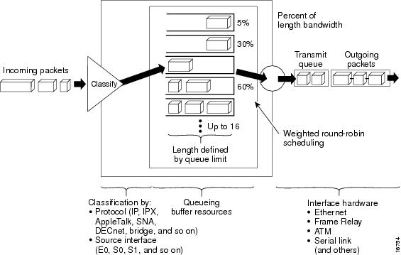
CQ ensures that no application or specified group of applications achieves more than a predetermined proportion of overall capacity when the line is under stress. Like PQ, CQ is statically configured and does not automatically adapt to changing network conditions.
On most platforms, all protocols are classified in the fast-switching path.
Determining Byte Count Values for Queues
In order to allocate bandwidth to different queues, you must specify the byte count for each queue.
How the Byte Count Is Used
The router sends packets from a particular queue until the byte count is exceeded. Once the byte count value is exceeded, the packet that is currently being sent will be completely sent. Therefore, if you set the byte count to 100 bytes and the packet size of your protocol is 1024 bytes, then every time this queue is serviced, 1024 bytes will be sent, not 100 bytes.
For example, suppose one protocol has 500-byte packets, another has 300-byte packets, and a third has 100-byte packets. If you want to split the bandwidth evenly across all three protocols, you might choose to specify byte counts of 200, 200, and 200 for each queue. However, this configuration does not result in a 33/33/33 ratio. When the router services the first queue, it sends a single 500-byte packet; when it services the second queue, it sends a 300-byte packet; and when it services the third queue, it sends two 100-byte packets. The effective ratio is 50/30/20.
Thus, setting the byte count too low can result in an unintended bandwidth allocation.
However, very large byte counts will produce a "jerky" distribution. That is, if you assign 10 KB, 10 KB, and 10 KB to three queues in the example given, each protocol is serviced promptly when its queue is the one being serviced, but it may be a long time before the queue is serviced again. A better solution is to specify 500-byte, 600-byte, and 500-byte counts for the queue. This configuration results in a ratio of 31/38/31, which may be acceptable.
In order to service queues in a timely manner and ensure that the configured bandwidth allocation is as close as possible to the required bandwidth allocation, you must determine the byte count based on the packet size of each protocol, otherwise your percentages may not match what you configure.
Note | Some protocols, such as Internetwork Packet Exchange (IPX), will negotiate the frame size at session startup time. |
Determining the Byte Count
DETAILED STEPS
| Step 1 |
For each queue, divide the percentage of bandwidth you want to allocate to the queue by the packet size, in bytes. For example, assume the packet size for protocol A is 1086 bytes, protocol B is 291 bytes, and protocol C is 831 bytes. We want to allocate 20 percent for A, 60 percent for B, and 20 percent for C. The ratios would be:
20/1086, 60/291, 20/831 or 0.01842, 0.20619, 0.02407 |
| Step 2 |
Normalize the numbers by dividing by the lowest number:
1, 11.2, 1.3 The result is the ratio of the number of packets that must be sent so that the percentage of bandwidth that each protocol uses is approximately 20, 60, and 20 percent. |
| Step 3 |
A fraction in any of the ratio values means that an additional packet will be sent. Round up the numbers to the next whole number to obtain the actual packet count.
In this example, the actual ratio will be 1 packet, 12 packets, and 2 packets. |
| Step 4 |
Convert the packet number ratio into byte counts by multiplying each packet count by the corresponding packet size.
In this example, the number of packets sent is one 1086-byte packet, twelve 291-byte packets, and two 831-byte packets, or 1086, 3492, and 1662 bytes, respectively, from each queue. These are the byte counts you would specify in your CQ configuration. |
| Step 5 |
To determine the bandwidth distribution this ratio represents, first determine the total number of bytes sent after all three queues are serviced:
(1 * 1086) + (12 * 291) + (2 * 831) = 1086 + 3492 + 1662 = 6240 |
| Step 6 |
Then determine the percentage of the total number of bytes sent from each queue:
1086/6240, 3492/6240, 1662/6240 = 17.4, 56, and 26.6 percent This result is close to the desired ratio of 20/60/20. |
| Step 7 | If the actual bandwidth is not close enough to the desired bandwidth, multiply the original ratio of 1:11.2:1.3 by the best value, trying to get as close to three integer values as possible. Note that the multiplier you use need not be an integer. For example, if we multiply the ratio by two, we get 2:22.4:2.6. We would now send two 1086-byte packets, twenty-three 291-byte packets, and three 831-byte packets, or 2172/6693/2493, for a total of 11,358 bytes. The resulting ratio is 19/59/22 percent, which is much closer to the desired ratio that we achieved. |
What to Do Next
The bandwidth that a custom queue will receive is given by the following formula:
(queue byte count / total byte count of all queues) * bandwidth capacity of the interface
where bandwidth capacity is equal to the interface bandwidth minus the bandwidth for priority queues.
Window Size
Window size also affects the bandwidth distribution. If the window size of a particular protocol is set to one, then that protocol will not place another packet into the queue until it receives an acknowledgment. The CQ algorithm moves to the next queue if the byte count is exceeded or no packets are in that queue.
Therefore, with a window size of one, only one frame will be sent each time. If your frame count is set to 2 kilobytes, and your frame size is 256 bytes, then only 256 bytes will be sent each time this queue is serviced.
Why Use CQ
You can use the Cisco IOS QoS CQ feature to provide specific traffic guaranteed bandwidth at a potential congestion point, assuring the traffic a fixed portion of available bandwidth and leaving the remaining bandwidth to other traffic. For example, you could reserve half of the bandwidth for SNA data, allowing the remaining half to be used by other protocols.
If a particular type of traffic is not using the bandwidth reserved for it, then unused bandwidth can be dynamically allocated to other traffic types.
Priority Queueing
PQ allows you to define how traffic is prioritized in the network. You configure four traffic priorities. You can define a series of filters based on packet characteristics to cause the router to place traffic into these four queues; the queue with the highest priority is serviced first until it is empty, then the lower queues are serviced in sequence.
For information on how to configure PQ, see the "Configuring Priority Queueing" module.
How It Works
During transmission, PQ gives priority queues absolute preferential treatment over low priority queues; important traffic, given the highest priority, always takes precedence over less important traffic. Packets are classified based on user-specified criteria and placed into one of the four output queues--high, medium, normal, and low--based on the assigned priority. Packets that are not classified by priority fall into the normal queue. The figure below illustrates this process.
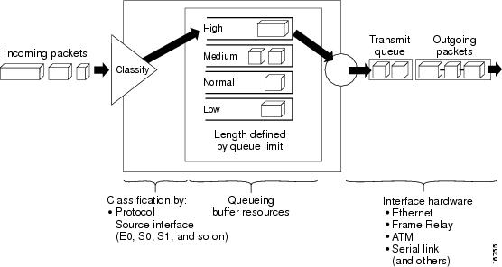
When a packet is to be sent out an interface, the priority queues on that interface are scanned for packets in descending order of priority. The high priority queue is scanned first, then the medium priority queue, and so on. The packet at the head of the highest queue is chosen for transmission. This procedure is repeated every time a packet is to be sent.
The maximum length of a queue is defined by the length limit. When a queue is longer than the queue limit, all additional packets are dropped.
Note | The priority output queueing mechanism can be used to manage traffic from all networking protocols. Additional fine-tuning is available for IP and for setting boundaries on the packet size. |
How Packets Are Classified for Priority Queueing
A priority list is a set of rules that describe how packets should be assigned to priority queues. A priority list might also describe a default priority or the queue size limits of the various priority queues.
Packets can be classified by the following criteria:
- Protocol or subprotocol type
- Incoming interface
- Packet size
- Fragments
- Access list
Keepalives sourced by the network server are always assigned to the high priority queue; all other management traffic (such as Interior Gateway Routing Protocol (IGRP) updates) must be configured. Packets that are not classified by the priority list mechanism are assigned to the normal queue.
Why Use Priority Queueing
PQ provides absolute preferential treatment to high priority traffic, ensuring that mission-critical traffic traversing various WAN links gets priority treatment. In addition, PQ provides a faster response time than do other methods of queueing.
Although you can enable priority output queueing for any interface, it is best used for low-bandwidth, congested serial interfaces.
Restrictions
When choosing to use PQ, consider that because lower priority traffic is often denied bandwidth in favor of higher priority traffic, use of PQ could, in the worst case, result in lower priority traffic never being sent. To avoid inflicting these conditions on lower priority traffic, you can use traffic shaping or CAR to rate-limit the higher priority traffic.
PQ introduces extra overhead that is acceptable for slow interfaces, but may not be acceptable for higher speed interfaces such as Ethernet. With PQ enabled, the system takes longer to switch packets because the packets are classified by the processor card.
PQ uses a static configuration and does not adapt to changing network conditions.
PQ is not supported on any tunnels.
Bandwidth Management
RSVP, CBWFQ, LLQ, IP RTP Priority, Frame Relay IP RTP Priority, and Frame Relay PIPQ can all reserve and consume bandwidth, up to a maximum of the reserved bandwidth on an interface.
To allocate bandwidth, you can use one of the following commands:
- For RSVP, use the ip rsvp bandwidth command.
- For CBWFQ, use the bandwidth policy-map class configuration command. For more information on CBWFQ bandwidth allocation, see the section Class-Based Weighted Fair Queueing in this module. For LLQ, you can allocate bandwidth using the priority command. For more information on LLQ bandwidth allocation, see the section Frame Relay PVC Interface Priority Queueing in this module.
- For IP RTP Priority, use the ip rtp prioritycommand. For more information on IP RTP Priority bandwidth allocation, see the section IP RTP Priority in this module.
- For Frame Relay IP RTP Priority, use the frame-relay ip rtp priority command. For more information on Frame Relay IP RTP Priority, see the section Frame Relay IP RTP Priority in this module.
- For Frame Relay PVC Interface Priority Queueing, use the frame-relay interface-queue priority command. For more information on Frame Relay PIPQ, see the section Frame Relay PVC Interface Priority Queueing in this module.
When you configure these commands, be aware of bandwidth limitations and configure bandwidth according to requirements in your network. Remember, the sum of all bandwidths cannot exceed the maximum reserved bandwidth. The default maximum bandwidth is 75 percent of the total available bandwidth on the interface. The remaining 25 percent of bandwidth is used for overhead, including Layer 2 overhead, routing traffic, and best-effort traffic.
Cisco and the Cisco logo are trademarks or registered trademarks of Cisco and/or its affiliates in the U.S. and other countries. To view a list of Cisco trademarks, go to this URL: www.cisco.com/go/trademarks. Third-party trademarks mentioned are the property of their respective owners. The use of the word partner does not imply a partnership relationship between Cisco and any other company. (1110R)
Any Internet Protocol (IP) addresses and phone numbers used in this document are not intended to be actual addresses and phone numbers. Any examples, command display output, network topology diagrams, and other figures included in the document are shown for illustrative purposes only. Any use of actual IP addresses or phone numbers in illustrative content is unintentional and coincidental.