
 Feedback
Contents
- QoS Tunnel Marking for GRE Tunnels
- Finding Feature Information
- Prerequisites for QoS Tunnel Marking for GRE Tunnels
- Restrictions for QoS Tunnel Marking for GRE Tunnels
- Information About QoS Tunnel Marking for GRE Tunnels
- GRE Definition
- GRE Tunnel Marking Overview
- GRE Tunnel Marking and the MQC
- GRE Tunnel Marking and DSCP or IP Precedence Values
- Benefits of GRE Tunnel Marking
- GRE Tunnel Marking and Traffic Policing
- GRE Tunnel Marking Values
- How to Configure Tunnel Marking for GRE Tunnels
- Configuring a Class Map
- Creating a Policy Map
- Attaching the Policy Map to an Interface or a VC
- Verifying the Configuration of Tunnel Marking for GRE Tunnels
- Troubleshooting Tips
- Configuration Examples for QoS Tunnel Marking for GRE Tunnels
- Example: Configuring Tunnel Marking for GRE Tunnels
- Example: Verifying the Tunnel Marking for GRE Tunnels Configuration
- Additional References
- Feature Information for QoS Tunnel Marking for GRE Tunnels
QoS Tunnel Marking for GRE Tunnels
The QoS Tunnel Marking for GRE Tunnels feature introduces the capability to define and control the quality of service (QoS) for both incoming and outgoing customer traffic on the provider edge (PE) router in a service provider network.
- Finding Feature Information
- Prerequisites for QoS Tunnel Marking for GRE Tunnels
- Restrictions for QoS Tunnel Marking for GRE Tunnels
- Information About QoS Tunnel Marking for GRE Tunnels
- How to Configure Tunnel Marking for GRE Tunnels
- Configuration Examples for QoS Tunnel Marking for GRE Tunnels
- Additional References
- Feature Information for QoS Tunnel Marking for GRE Tunnels
Finding Feature Information
Your software release may not support all the features documented in this module. For the latest feature information and caveats, see the release notes for your platform and software release. To find information about the features documented in this module, and to see a list of the releases in which each feature is supported, see the Feature Information Table at the end of this document.
Use Cisco Feature Navigator to find information about platform support and Cisco software image support. To access Cisco Feature Navigator, go to www.cisco.com/go/cfn. An account on Cisco.com is not required.
Prerequisites for QoS Tunnel Marking for GRE Tunnels
- You must determine the topology and interfaces that need to be configured to mark incoming and outgoing traffic.
Information About QoS Tunnel Marking for GRE Tunnels
- GRE Definition
- GRE Tunnel Marking Overview
- GRE Tunnel Marking and the MQC
- GRE Tunnel Marking and DSCP or IP Precedence Values
- Benefits of GRE Tunnel Marking
GRE Definition
Generic routing encapsulation (GRE) is a tunneling protocol developed by Cisco that can encapsulate a wide variety of protocol packet types inside IP tunnels, creating a virtual point-to-point link to Cisco routers at remote points over an IP internetwork.
GRE Tunnel Marking Overview
 Note | The set ip {dscp | precedence} [tunnel] command is equivalent to the set {dscp | precedence} [tunnel] command. |
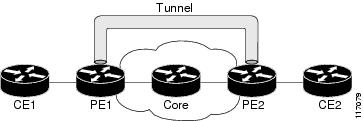
The figure below shows traffic being received from the CE1 router through the incoming interface on the PE1 router on which tunnel marking occurs. The traffic is encapsulated (tunneled), and the tunnel header is marked on the PE1 router. The marked packets travel (tunnel) through the core and are decapsulated automatically on the exit interface of the PE2 router. This feature is designed to simplify classifying customer edge (CE) traffic and is configured only in the service provider network. This process is transparent to the customer sites. The CE1 and CE2 routers exist as a single network.
GRE Tunnel Marking and the MQC
Before you can configure tunnel marking for GRE tunnels, you must first configure a class map and a policy map and then attach that policy map to the appropriate interface. These three tasks can be accomplished by using the MQC.
For information on using the MQC, see the "Applying QoS Features Using the MQC" module.
GRE Tunnel Marking and DSCP or IP Precedence Values
GRE tunnel marking is configured with the set ip precedence tunnel or set ip dscp tunnel command on PE routers that carry incoming traffic from customer sites. GRE tunnel marking allows you to mark the header of a GRE tunnel by setting a DSCP value from 0 to 63 or an IP precedence value from 0 to 7 to control GRE tunnel traffic bandwidth and priority.
GRE traffic can also be marked under traffic policing with the set-dscp-tunnel-transmit and the set-prec-tunnel-transmit actions (or keywords) of the police command. The tunnel marking value is from 0 to 63 for the set-dscp-tunnel-transmit actions and from 0 to 7 for the set-prec-tunnel-transmit command. Under traffic policing, tunnel marking can be applied with conform, exceed, and violate action statements, allowing you to automatically apply a different value for traffic that does not conform to the expected traffic rate.
After the tunnel header is marked, GRE traffic is carried through the tunnel and across the service provider network. This traffic is decapsulated on the interface of the PE router that carries the outgoing traffic to the other customer site. The configuration of GRE tunnel marking is transparent to customer sites. All internal configuration is preserved.
There is a different between the set ip precedence and set ip dscp commands and the set ip precedence tunnel and set ip dscp tunnel commands:
- The set ip precedence and set ip dscp commands are used to set the IP precedence value or DSCP value in the header of an IP packet.
- The set ip precedence tunnel and set ip dscp tunnel commands are used to set (mark) the IP precedence value or DSCP value in the tunnel header that encapsulates the GRE traffic.
- The set ip precedence tunnel and set ip dscp tunnel commands have no effect on egress traffic that is not encapsulated in a GRE tunnel.
Benefits of GRE Tunnel Marking
GRE tunnel marking provides a simple mechanism to control the bandwidth of customer GRE traffic. The QoS Tunnel Marking for GRE Tunnels feature is configured entirely within the service provider network and on interfaces that carry incoming and outgoing traffic on the PE routers.
GRE Tunnel Marking and Traffic Policing
Traffic policing allows you to control the maximum rate of traffic sent or received on an interface and to partition a network into multiple priority levels or class of service (CoS). If you use traffic policing in your network, you can also implement the GRE tunnel marking feature with the set-dscp-tunnel-transmit or set-prec-tunnel-transmit action (or keyword) of the police command in policy-map class configuration mode. Under traffic policing, tunnel marking can be applied with conform, exceed, and violate action statements, allowing you to apply a different value automatically for traffic that does not conform to the expected traffic rate.
How to Configure Tunnel Marking for GRE Tunnels
- Configuring a Class Map
- Creating a Policy Map
- Attaching the Policy Map to an Interface or a VC
- Verifying the Configuration of Tunnel Marking for GRE Tunnels
Configuring a Class Map
DETAILED STEPS
Creating a Policy Map
DETAILED STEPS
| Command or Action | Purpose | |
|---|---|---|
Step 1 |
enable
Example: Router> enable |
Enables privileged EXEC mode. |
Step 2 |
configure
terminal
Example: Router# configure terminal |
Enters global configuration mode. |
Step 3 |
policy-map
policy-map-name
Example: Router(config)# policy-map TUNNEL_MARKING |
Creates or modifies a policy map that can be attached to one or more interfaces to specify a service policy, and enters QoS policy-map configuration mode. |
Step 4 |
class
{class-name |
class-default}
Example: Router(config-pmap)# class MATCH_PREC |
Specifies the name of the class whose policy you want to create or change or specifies the default class (commonly known as the class-default class) before you configure its policy. |
Step 5 |
set
ip
precedence
tunnel
precedence-value
Example: Router(config-pmap-c)# set ip precedence tunnel 3 |
Sets the IP precedence value in the tunnel header of a GRE-tunneled packet on the ingress interface. The tunnel marking value is a number from 0 to 7 when IP precedence is configured. |
Step 6 |
exit
Example: Router(config-pmap-c)# exit |
Returns to QoS policy-map configuration mode. |
Step 7 |
class
{class-name |
class-default}
Example: Router(config-pmap)# class MATCH_DSCP |
Specifies the name of the class whose policy you want to create or change or specifies the default class (commonly known as the class-default class) before you configure its policy.
|
Step 8 |
set
ip
dscp
tunnel
dscp-value
Example: Router(config-pmap-c)# set ip dscp tunnel 3 |
Sets the differentiated services code point (DSCP) value in the tunnel header of a GRE-tunneled packet on the ingress interface. The tunnel marking value is a number from 0 to 63 when DSCP is configured. |
Step 9 |
end
Example: Router(config-pmap-c)# end |
(Optional) Returns to privileged EXEC mode. |
Attaching the Policy Map to an Interface or a VC
Note | Tunnel marking policy can be applied on Ingress or Egress direction. A tunnel marking policy can be applied as an ingress policy on the ingress physical interface of a Service Provider Edge (SPE) router or as an egress policy on a tunnel interface. |
DETAILED STEPS
| Command or Action | Purpose | |
|---|---|---|
Step 1 |
enable
Example: Router> enable |
Enables privileged EXEC mode.
|
Step 2 |
configure
terminal
Example: Router# configure terminal |
Enters global configuration mode. |
Step 3 |
interface
type
number
Example: Router(config)# interface GigabitEthernet 0/0/1 |
Configures an interface type and enters interface configuration mode. |
Step 4 |
service-policy
{input |
output}
policy-map-name
Example: Router(config-if)# service-policy input TUNNEL_MARKING |
Specifies the name of the policy map to be attached to the input or output direction of the interface.
|
Step 5 |
end
Example: Router(config-if)# end |
(Optional) Returns to privileged EXEC mode. |
Verifying the Configuration of Tunnel Marking for GRE Tunnels
Use the show commands in this procedure to view the GRE tunnel marking configuration settings. The show commands are optional and can be entered in any order.
DETAILED STEPS
| Command or Action | Purpose | |
|---|---|---|
Step 1 |
enable
Example: Router> enable |
Enables privileged EXEC mode.
|
Step 2 |
show
policy-map
interface
interface-name
Example: Router# show policy-map interface GigabitEthernet0/0/1 |
(Optional) Displays the packet statistics of all classes that are configured for all service policies either on the specified interface or subinterface. |
Step 3 |
show
policy-map
policy-map
Example: Router# show policy-map TUNNEL_MARKING |
(Optional) Displays the configuration of all classes for a specified service policy map or all classes for all existing policy maps. |
Step 4 |
exit
Example: Router# exit |
(Optional) Returns to user EXEC mode. |
Troubleshooting Tips
If you find that the configuration is not functioning as expected, perform these operations to troubleshoot the configuration:
- Use the show running-config command and analyze the output of the command.
- If the policy map does not appear in the output of the show running-config command, enable the logging console command.
- Attach the policy map to the interface again.
Configuration Examples for QoS Tunnel Marking for GRE Tunnels
- Example: Configuring Tunnel Marking for GRE Tunnels
- Example: Verifying the Tunnel Marking for GRE Tunnels Configuration
Example: Configuring Tunnel Marking for GRE Tunnels
The following is an example of a GRE tunnel marking configuration. In this example, a class map called "MATCH_PREC" has been configured to match traffic based on the DSCP value.
Router> enable
Router# configure terminal
Router(config)# class-map MATCH_DSCP
Router(config-cmap)# match ip dscp 0
Router(config-cmap)# end
In the following part of the example configuration, a policy map called "TUNNEL_MARKING" has been created and the set ip dscp tunnel command has been configured in the policy map. You could use the set ip precedence tunnel command instead of the set ip dscp tunnel command if you do not use DSCP in your network.
Router(config)# policy-map TUNNEL_MARKING
Router(config-pmap)# class MATCH_DSCP
Router(config-pmap-c)# set ip dscp tunnel 3
Router(config-pmap-c)# end
Note | The following part of the example configuration is not required to configure this feature if you use the set ip dscp tunnel or set ip precedence tunnel commands to enable GRE tunnel marking. This example shows how GRE tunnel marking can be enabled under traffic policing. |
In the following part of the example configuration, the policy map called "TUNNEL_MARKING" has been created and traffic policing has also been configured by using the police command and specifying the appropriate policing actions. The set-dscp-tunnel-transmit command can be used instead of the set-prec-tunnel-transmit command if you use DSCP in your network.
Router(config)# policy-map TUNNEL_MARKING
Router(config-pmap)# class class-default
Router(config-pmap-c)# police 8000 conform-action set-prec-tunnel-transmit 4 exceed-action set-prec-tunnel-transmit 0
Router(config-pmap-c)# end
In the following part of the example configuration, the policy map is attached to GigabitEthernet interface 0/0/1 in the inbound (input) direction by specifying the input keyword of the service-policy command:
Router(config)# interface GigabitEthernet 0/0/1
Router(config-if)# service-policy input TUNNEL_MARKING
Router(config-if)# end
In the final part of the example configuration, the policy map is attached to tunnel interface 0 in the outbound (output) direction using the output keyword of the service-policy command:
Router(config)# interface Tunnel 0
Router(config-if)# service-policy output TUNNEL_MARKING
Router(config-if)# end
Example: Verifying the Tunnel Marking for GRE Tunnels Configuration
This section contains sample output from the show policy-map interface and the show policy-map commands. The output from these commands can be used to verify and monitor the feature configuration in your network.
- The character string "ip dscp tunnel 3" indicates that GRE tunnel marking has been configured to set the DSCP value in the header of a GRE-tunneled packet.
- The character string "ip precedence tunnel 3" indicates that GRE tunnel marking has been configured to set the precedence value in the header of a GRE-tunneled packet.
Router# show policy-map interface GigabitEthernet0/0/1
 Service-policy input: TUNNEL_MARKING

    Class-map: MATCH_PREC (match-any)
      22 packets, 7722 bytes
      5 minute offered rate 0000 bps, drop rate 0000 bps
      Match: ip precedence 0
      QoS Set
        ip precedence tunnel 3
          Marker statistics: Disabled

    Class-map: MATCH_DSCP (match-any)
      0 packets, 0 bytes
      5 minute offered rate 0000 bps, drop rate 0000 bps
      Match: ip dscp default (0)
      QoS Set
        ip dscp tunnel 3
          Marker statistics: Disabled

    Class-map: class-default (match-any)
      107 packets, 8658 bytes
      5 minute offered rate 0000 bps, drop rate 0000 bps
      Match: any
The following is sample output from the show policy-map command. In this sample output, the character string "ip precedence tunnel 3" indicates that the GRE tunnel marking feature has been configured to set the IP precedence value in the header of an GRE-tunneled packet.
Router# show policy-map

Policy Map TUNNEL_MARKING
    Class MATCH_PREC
      set ip precedence tunnel 3
    Class MATCH_DSCP
      set ip dscp tunnel 3
Additional References
Related Documents
|
Related Topic |
Document Title |
|---|---|
|
Cisco IOS commands |
|
|
QoS commands: complete command syntax, command modes, command history, defaults, usage guidelines, and examples |
Cisco IOS Quality of Service Solutions Command Reference |
|
MQC |
"Applying QoS Features Using the MQC" module |
|
Tunnel marking for Layer 2 Tunnel Protocol Version 3 (L2TPv3) tunnels |
"QoS: Tunnel Marking for L2TPv3 Tunnels" module |
|
DSCP |
"Overview of DiffServ for Quality of Service" module |
MIBs
Technical Assistance
|
Description |
Link |
|---|---|
|
The Cisco Support and Documentation website provides online resources to download documentation, software, and tools. Use these resources to install and configure the software and to troubleshoot and resolve technical issues with Cisco products and technologies. Access to most tools on the Cisco Support and Documentation website requires a Cisco.com user ID and password. |
Feature Information for QoS Tunnel Marking for GRE Tunnels
The following table provides release information about the feature or features described in this module. This table lists only the software release that introduced support for a given feature in a given software release train. Unless noted otherwise, subsequent releases of that software release train also support that feature.
Use Cisco Feature Navigator to find information about platform support and Cisco software image support. To access Cisco Feature Navigator, go to www.cisco.com/go/cfn. An account on Cisco.com is not required.
| Table 1 | Feature Information for QoS Tunnel Marking for GRE Tunnels |
|
Feature Name |
Releases |
Feature Information |
||
|---|---|---|---|---|
|
QoS Tunnel Marking for GRE Tunnels |
12.4(15)T2 12.2(33)SRC 12.2(33)SB |
The QoS Tunnel Marking for GRE Tunnels feature introduces the capability to define and control the QoS for incoming customer traffic on the PE router in a service provider network.
The following commands were introduced or modified: match atm-clp, match cos, match fr-de, police, police (two rates), set ip dscp tunnel, set ip precedence tunnel, show policy-map, show policy-map interface. |
||
|
Egress DSCP Marking for GRE Tunnels |
15.2(2)T |
The Egress DSCP Marking for GRE Tunnels feature allows you to mark the DSCP in the tunnel header using an output service-policy attached to the tunnel. |
Cisco and the Cisco logo are trademarks or registered trademarks of Cisco and/or its affiliates in the U.S. and other countries. To view a list of Cisco trademarks, go to this URL: www.cisco.com/go/trademarks. Third-party trademarks mentioned are the property of their respective owners. The use of the word partner does not imply a partnership relationship between Cisco and any other company. (1110R)
Any Internet Protocol (IP) addresses and phone numbers used in this document are not intended to be actual addresses and phone numbers. Any examples, command display output, network topology diagrams, and other figures included in the document are shown for illustrative purposes only. Any use of actual IP addresses or phone numbers in illustrative content is unintentional and coincidental.