
 Feedback
Contents
- MPLS Point-to-Multipoint Traffic Engineering
- Finding Feature Information
- Prerequisites for MPLS Point-to-Multipoint Traffic Engineering
- Restrictions for MPLS Point-to-Multipoint Traffic Engineering
- Information About MPLS Point-to-Multipoint Traffic Engineering
- MPLS Point-to-Multipoint Traffic Engineering Overview
- How P2MP TE Sub-LSPs Are Signaled
- How P2MP TE Traffic Is Forwarded
- Computing the IGP Path Using Dynamic Paths or Explicit Paths
- Remerge Events
- Crossover Events
- Benefits of MPLS Point-to-Multipoint Traffic Engineering
- MPLS Point-to-Multipoint Traffic Engineering--Re-optimizing Traffic
- P2P TE Tunnels Coexist with P2MP TE Tunnels
- Using FRR to Protect P2MP TE Links
- FRR Failure Detection Mechanisms
- Bandwidth Preemption for P2MP TE
- How to Configure MPLS Point-to-Multipoint Traffic Engineering
- Configuring the Headend Routers
- Configuring the Midpoint Routers
- Configuring the Tailend Routers
- Configuring FRR with P2MP TE Tunnels
- Enabling MPLS Traffic Engineering System Logging of Events
- Verifying the Configuration of MPLS Point-to-Multipoint Traffic Engineering
- Verifying the Configuration of the Headend Router
- Verifying the Configuration of the Midpoint Routers
- Verifying the Configuration of the Tailend Routers
- Configuration Examples for MPLS Point-to-Multipoint Traffic Engineering
- Example Configuration of the Headend Router (PE5)
- Example Configuration of the Midpoint Router (P1)
- Example Configuration of the Tailend Router (PE1)
- Additional References
- Feature Information for MPLS Point-to-Multipoint Traffic Engineering
- Glossary
MPLS Point-to-Multipoint Traffic Engineering
The MPLS Point-to-Multipoint Traffic Engineering feature enables you to forward Multiprotocol Label Switching (MPLS) traffic from one source to multiple destinations. Cisco nonstop forwarding (NSF) and stateful switchover (SSO) (NSF/SSO) provides for minimal disruption of Point-to-Multipoint (P2MP) Traffic Engineering (TE) tunnel traffic if a Route Processor has a catastrophic failure. Traffic loss varies by platform.
For more information on configuring NSF/SSO with this feature, see NSF/SSO--MPLS TE and RSVP Graceful Restart.
- Finding Feature Information
- Prerequisites for MPLS Point-to-Multipoint Traffic Engineering
- Restrictions for MPLS Point-to-Multipoint Traffic Engineering
- Information About MPLS Point-to-Multipoint Traffic Engineering
- How to Configure MPLS Point-to-Multipoint Traffic Engineering
- Configuration Examples for MPLS Point-to-Multipoint Traffic Engineering
- Additional References
- Feature Information for MPLS Point-to-Multipoint Traffic Engineering
- Glossary
Finding Feature Information
Your software release may not support all the features documented in this module. For the latest feature information and caveats, see the release notes for your platform and software release. To find information about the features documented in this module, and to see a list of the releases in which each feature is supported, see the Feature Information Table at the end of this document.
Use Cisco Feature Navigator to find information about platform support and Cisco software image support. To access Cisco Feature Navigator, go to www.cisco.com/go/cfn. An account on Cisco.com is not required.
Prerequisites for MPLS Point-to-Multipoint Traffic Engineering
Before configuring the MPLS Point-to-Multipoint Traffic Engineering (P2MP TE) feature, note the following:
- Configure Resource Reservation Protocol (RSVP) and traffic engineering features on the headend, midpoint, and tailend routers in the MPLS network.
- Cisco nonstop NSF/SSO is supported only on platforms with dual Route Processors on which NSF/SSO is configured.
- For NSF/SSO support, all routers (headend, midpoint, and tailend) must be Cisco 7600 series routers.
- All routers must be configured for RSVP graceful restart. For more information, see NSF/SSO--MPLS TE and RSVP Graceful Restart.
Restrictions for MPLS Point-to-Multipoint Traffic Engineering
The following functionality is not supported:
- The P2MP TE feature is not supported in inter-area and autonomous system networks. All P2MP TE sub-label switched paths (LSPs) must originate and terminate in the same IGP and autonomous system domain.
- Only link protection, not node and path protection, for P2MP sub-LSPs is supported.
- The P2MP TE feature does not support Protocol Independent Multicast (PIM) sparse mode. Only PIM source-specific multicast (SSM) is supported.
- You must manually add and remove destinations at the headend router; dynamic adding and removal of destinations is not supported.
- RFC 4090 describes two FRR methods: Facility and Detour backup. Both point-to-point (P2P) TE and P2MP TE support only the Facility FRR method.
- P2MP TE does not support the MIBs for P2MP tunnels as described in draft-ietf-mpls-p2mp-te-mib-09.txt. The P2MP TE headend interfaces are represented in the mplsTunnelTable of the MPLS-TE-STD-MIB. However, sub-LSP-related information is not supported by the MPLS-TE-STD-MIB.
- The MPLS LSP Ping and MPLS Operations, Administration, and Maintenance (OAM) features are not supported.
- MPLS P2MP TE tunnels and IP multicast (MFIB) do not support fragmentation. Configure MTU values on the ingress interface of the headend router.
-
The following restrictions apply when port-channels are coupled with MPLS TE Fast Reroute (FRR):
- Active and backup ports must be port-channel interfaces.
- All members of the primary port-channel interfaces must be on the same slot.
- On Cisco 7600 series routers, when FRR protection is enabled for a sub-LSP, all members of the backup port-channel must be on the same slot but different from the primary port-channel.
- On Cisco 7600 series routers with non-S chassis, traffic loss can be up to 2 seconds.
- Multiple path options per destination are not supported. The P2MP TE feature allows one path option for each destination.
- The tunneldestination command is not supported with point-to-multipoint traffic engineering tunnels. Instead, use the mplstraffic-engdestinationlist command.
- Multiple path options per sub-LSP (destination) are not supported. The P2MP TE feature allows one path option for each sub-LSP.
- The tunnelmplstraffic-engautorouteannounce command is not supported with this feature; it is supported only with IP unicast traffic.
- If P2MP sub-LSPs are signaled from R1->R2->R3 and a P2P tunnel is signaled from R3->R2->R1, then issue themplstraffic-engmulticast-intactcommand on R3 in IGP configuration mode under router OSPF or IS-IS to ensure accommodate multicast traffic for R3's sub-LSPs.
- The P2MP TE feature does not support policy-based routing.
- The P2MP TE feature cannot be configured with static IP routes.
Information About MPLS Point-to-Multipoint Traffic Engineering
- MPLS Point-to-Multipoint Traffic Engineering Overview
- How P2MP TE Sub-LSPs Are Signaled
- How P2MP TE Traffic Is Forwarded
- Computing the IGP Path Using Dynamic Paths or Explicit Paths
- Benefits of MPLS Point-to-Multipoint Traffic Engineering
- MPLS Point-to-Multipoint Traffic Engineering--Re-optimizing Traffic
- P2P TE Tunnels Coexist with P2MP TE Tunnels
- Using FRR to Protect P2MP TE Links
- Bandwidth Preemption for P2MP TE
MPLS Point-to-Multipoint Traffic Engineering Overview
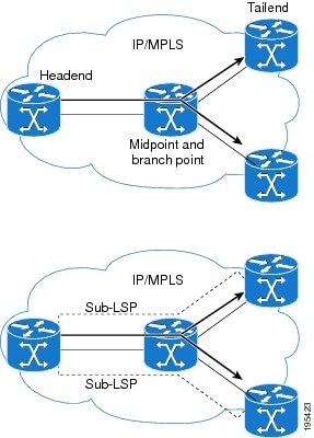
A P2MP TE network contains the following elements, which are shown in the figure below:
- The headend router, also called the source or ingress router, is where the label switched path (LSP) is initiated. The headend router can also be a branch point, which means the router performs packet replication and the sub-LSPs split into different directions.
- The midpoint router is where the sub-LSP signaling is processed. The midpoint router can be a branch point.
- The tailend router, also called the destination, egress, or leaf-node router, is where sub-LSP signaling ends.
- A bud router is a midpoint and tailend router at the same time.
- A P2MP tunnel consists of one or more sub-LSPs. All sub-LSPs belonging to the same P2MP tunnel employ the same constraints, protection policies, and so on, which are configured at the headend router.
P2MP TE tunnels build on the features that exist in basic point-to-point TE tunnels. The P2MP TE tunnels have the following characteristics:
- There is one source (headend) but more than one destination (tailend).
- They are unidirectional.
- They are explicitly routed.
- Multiple sub-LSPs connect the headend router to various tailend routers.
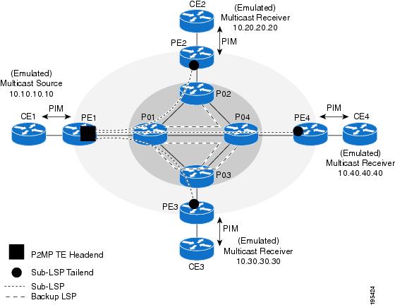
The figure below shows a P2MP TE tunnel that has three destinations.
- PE1 is the headend router.
- P01 is a branch point router, where packet replication occurs.
- PE2, PE3, and PE4 are tailend routers, where the sub-LSP ends.
Between the PE and CE routers, PIM is enabled to exchange multicast routing information with the directly connected customer edge (CE) routers. PIM is not enabled across the P2MP TE tunnel.
How P2MP TE Sub-LSPs Are Signaled
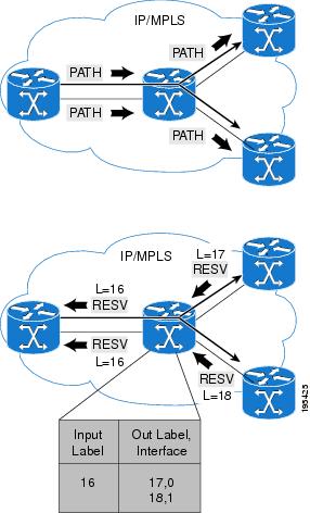
RSVP TE extensions defined in RFC 4875 allow multiple sub-LSPs to be signaled from the headend router. A P2MP TE tunnel consists of multiple sub-LSPs that connect the headend router to various tailend routers.
The headend router sends one RSVP path message to each destination. The tailend router replies with a RESV message. The Label Forwarding Information Base (LFIB) is populated using the RSVP labels allocated by the RESV messages.
The P2MP TE feature does not support signaling of multiple sub-LSPs in the same Path/Resv message. If multiple sub-LSPs occur in the same message, the router sends a PathErr Unknown Objects message, and the Path/Resv message with multiple sub-LSPs is not forwarded.
The tailend routers allocate unreserved labels, which are greater than 15 and do not include implicit or explicit null labels. Using unreserved labels allows IP multicast to perform a Reverse Path Forwarding (RPF) check on the tailend router. Because a sub-LSP tailend router cannot be represented as a regular interface, a special LSP virtual interface (VIF) is automatically created. The LSP VIF represents the originating interface for all IP multicast traffic originating from the P2MP TE tailend router.
The figure below shows the LSP signaling process.
How P2MP TE Traffic Is Forwarded
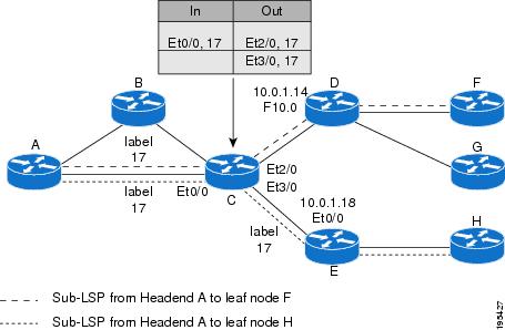
At the headend of the traffic engineering tunnel, through a static Internet Group Management Protocol (IGMP) group-to-tunnel mapping, IP multicast traffic is encapsulated with a unique MPLS label, which is associated with the P2MP TE tunnel. The multicast traffic is label switched in the P2MP tree and replicated at branch and bud nodes along the P2MP tree. When the labeled packet reaches the tailend (a PE router), the MPLS label is removed and forwarded to the IP multicast tree towards the end point.This process is shown in the figure below.
 Note | The P2MP TE feature does not support penultimate-hop popping. Therefore, the egress router must allocate an explicit null or non-null label. |
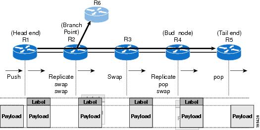
When sub-LSPs share a common router (branch point) and use the same ingress interface of the router, the same MPLS label is used for forwarding. The multicast state is built by reusing the MPLS labels at the branch points, as shown in the figure below, where MPLS label 17 is shared by two sub-LSPs that both use router C.
Computing the IGP Path Using Dynamic Paths or Explicit Paths
You can either specify explicit paths or allow paths to be created dynamically. You can also specify bandwidth parameters, which are flooded throughout the MPLS network through existing RSVP-TE extensions to Open Shortest Path First (OSPF) and Integrated Intermediate System-to-Intermediate System (IS-IS).
The MPLS core network uses RSVP to enable end-to-end IP multicast connectivity. The tailend router and the end point router use PIM to exchange multicast routing information with directly connected CE routers. PIM is not configured in the MPLS core.
P2MP TE tunnels can co-exist with regular P2P TE tunnels. Existing path calculation and bandwidth preemption rules apply in this case.
You create IGP paths by enabling dynamic path computation, configuring explicit paths through CLI commands, or using both methods in your P2MP TE network.
- Dynamic paths are created using Constrained Shortest Path First (CSPF) to determine the best path to a destination. CSPF uses path constraints, such as bandwidth, affinities, priorities, and so on, as part of the computation.
- Explicit paths allows you to manually specify the path a sub-LSP uses from the headend router to the tailend router. You configure static paths on the headend router.
Remerge Events
When explicit paths are configured with a limited number of equal cost links or paths, two sub-LSPs might connect at a midpoint router through different ingress interfaces, but use the same egress interface. This is called a remerge event, which can cause duplicate MPLS packets. If a router detects a remerge event, it sends a PathErr Routing Problem: Remerge Detected message toward the headend router and the sub-LSPs are not established. With dynamic paths, the router signals a path that avoids a remerge situation.
Crossover Events
With a P2MP tunnel, two sibling sub-LSPs (sub-LSPs that share the same link and label) are said to "cross over" when they have different incoming interfaces and different outgoing interfaces on the same intersecting node. The sibling sub-LSPs neither share input label nor output bandwidth. Avoid configuring crossover LSPs, because they waste bandwidth. However, the duplication of sub-LSPs does not result in an error.
Benefits of MPLS Point-to-Multipoint Traffic Engineering
The P2MP TE feature provides the following benefits:
- You can configure signaling attributes, such as affinities, administrative metrics, FRR protection, and bandwidth constraints, when you set up P2MP TE sub-LSPs.
- P2MP TE provides a single point of traffic control. You specify all the signaling and path parameters at the headend router.
- You can configure explicit paths to optimize traffic distribution.
- You can enable FRR link protection and bandwidth protection for P2MP TE sub-LSPs.
- Protocol Independent Multicast (PIM) is not needed in the MPLS core. Only the non-MPLS interfaces on the tailend routers need to be configured with PIM.
MPLS Point-to-Multipoint Traffic Engineering--Re-optimizing Traffic
A P2MP TE tunnel is operational (up) when the first sub-LSP has been successfully signaled. The P2MP TE tunnel is not operational (down) when all sub-LSPs are down. Certain events can trigger a tunnel re-optimization:
- One of the sub-LSPs is fast-rerouted to a backup tunnel (for dynamic LSPs).
- A link is operational. (if the command mplstraffic-engreoptimizeeventslink-up is configured).
- A periodic schedule optimization occurs through the mplstraffic-engreoptimizetimersfrequency command.
- The network administrator forces a tunnel optimization through the mplstraffic-engreoptimizecommand.
- An FRR protected interface becomes operational.
- A non-FRR LSP detects a remerge situation.
When a P2MP tunnel is reoptimized, a new LSP is signaled and traffic is moved to the new LSP.
To determine if a tunnel should be reoptimized, the router considers the following criteria:
- The router compares the number of reachable destinations between the new tree and current tree. If the new tree contains more reachable destinations than the current tree, the router performs a reoptimization. If the new tree contains fewer reachable destinations than the current tree, then the router keeps the current tree.
- The router verifies that the same set of reachable destinations in the current tree are also in the new tree. If the new tree does not contain the same destinations, the router keeps the current tree.
- The router compares the number of destinations in the new tree with the number of destinations in the old tree. If the number of destinations in the new tree is greater than the number of destinations in the current tree, the router switches to the new tree. This guarantees that the new tree will contain all of the existing destinations and more.
- The router compares the metric between the current and new tree to ensure the new tree and current tree contain the same set of reachable destinations.
- The router compares the administrative weights of the old tree and the new tree. The router switches to the new tree if the cumulative administrative weight is lower. This step applies as a tie breaker if all the other conditions are the same.
P2MP TE uses make-before-break reoptimization, which uses the following reoptimization process:
- The new LSP is signaled.
- The headend router initiates a timer to ensure sufficient time elapses before traffic moves from the current LSP to the new LSP.
- Traffic is redirected from the current LSP to the new LSP.
- The timer is started for the purpose of tearing down the old sub-LSPs.
P2P TE Tunnels Coexist with P2MP TE Tunnels
Both P2P and P2MP TE tunnels share the following characteristics:
- Tunnel bandwidth is configured the same way in both P2P and P2MP tunnels. In P2MP TE tunnels, any bandwidth parameters you configure are applied to all the destination routers. That is, the bandwidth parameters apply to all sub-LSPs. Both P2P and P2MP TE tunnels use the same IGP extension to flood link bandwidth information throughout the network.
- Tunnel setup and hold priorities, attributes flags, affinity and mask, and administrative weight parameters are configured the same way for P2P and P2MP TE tunnels. P2MP TE tunnel parameters apply to all sub-LSPs.
- FRR-enabled P2MP sub-LSPs coexist with FRR-enabled P2P LSPs in a network. For P2P TE, node, link, and bandwidth protection is supported. For P2MP TE, only link and bandwidth protection are supported.
- The method of computing the path dynamically through CSPF is the same for P2P and P2MP TE.
- Auto-tunnel backup behaves slightly different with P2P and P2MP tunnels. With P2P tunnels, auto-tunnel backup creates two backup tunnels: one for the node protection and one for the link protection. The node protection backup is preferred for P2P LSP protection. With P2MP tunnels, auto-tunnel backup creates one backup tunnel, which is the link protection. Only the link protection backup can be used for P2MP sub-LSPs. The P2P and P2MP tunnels can coexist and be protected.
Using FRR to Protect P2MP TE Links
FRR applies to P2P LSPs and P2MP sub-LSPs in the same manner. No new protocol extensions are needed to support P2MP.
FRR minimizes interruptions in traffic delivery as a result of link or node failure. FRR temporarily fast switches LSP traffic to a backup path around a network failure until the headend router signals a new end-to-end LSP.
FRR-enabled P2MP sub-LSPs coexist with FRR-enabled P2P LSPs in a network. For P2MP TE, only link and bandwidth protection is supported. Node, link, and bandwidth protection are supported for P2P TE.
You can configure P2P explicit backup tunnels on point of local repair (PLR) nodes for link protection of P2MP sub-LSPs, similar to LSPs for P2P TE tunnels. You can also enable automatic creation of backup tunnels using the Auto-tunnel Backup feature for P2P TE tunnels. All sibling sub-LSPs that share the same outgoing link are protected by the same backup tunnel. All cousin sub-LSPs that share the same outgoing link can be protected by multiple P2P backup tunnels.
Link protection for a P2MP TE tunnel is illustrated in the figure below, which shows PE1 as the tunnel headend router and PE2, PE3, and PE4 as tunnel tailend routers. The following sub-LSPs are signaled from PE1 in the network:
- From PE1 to PE2, the sub-LSP travels the following path: PE1 -> P01 -> P02 -> PE2
- From PE1 to PE3, the sub-LSP travels the following path: PE1 -> P01 -> P03 -> PE3
- From PE1 to PE4, the sub-LSP travels the following path: PE1 -> P01 -> P04 -> PE4
Node P01 is a branch node that does packet replication in the MPLS forwarding plane; ingress traffic originating from PE1 will be replicated towards routers P02, P03, and P04.
To protect the three sub-LSPs, separate point-to-point backup tunnels are signaled. Note that backup tunnels can be created only for links that have an alternative network path. In this example, router P01 is the Point of Local Repair (PLR) and routers P02, P03, and P04 are Merge Points (MPs).
If a link failure occurs between routers P01 and P04, the following events are triggered:
- Router P01 switches traffic destined to PE4 to the backup tunnel associated with P04.
- Router P01 sends RSVP path error messages upstream to the P2MP TE headend router PE1. At the same time, P01 and P04 send IGP updates (link state advertisements (LSAs)) to all adjacent IGP neighbors, indicating that the interfaces associated with links P01 through P04 are down.
- Upon receiving RSVP path error messages and IGP LSA updates, the headend router triggers a P2MP TE tunnel reoptimization and signals a new sub-LSP. (This occurs if you have specified dynamic path creation.)
Note | If only one sub-LSP becomes active, it remains down until all the sub-LSPs become active. |
FRR Failure Detection Mechanisms
To detect link failures in a P2MP TE network, you can use native link and interface failure detection mechanisms, such as bidirectional forwarding detection (BFD), loss of signal (LoS) failure events, and RSVP hellos.
Bidirectional Forwarding Detection
The MPLS Traffic Engineering: BFD-triggered FRR feature allows you to obtain link and node protection by using the Bidirectional Forwarding Detection (BFD) protocol to provide fast forwarding path failure detection times for all media types, encapsulations, topologies, and routing protocols. In addition to fast forwarding path failure detection, BFD provides a consistent failure detection method for network administrators. For more information, see MPLS Traffic Engineering: BFD-triggered Fast Reroute (FRR).
Loss of Signal Failure Events
FRR can be triggered by loss of signal events. It is alarm based and dependent upon platform and line card support. For more information, see MPLS TE: Link and Node Protection, with RSVP Hellos Support (with Fast Tunnel Interface Down Detection)
RSVP Hellos
You can configure RSVP hellos on interfaces that do not provide FRR cutover notification during a link failure. The behavior for RSVP hellos is similar for both P2MP TE and P2P TE. For every sub-LSP that has a backup tunnel and has RSVP hellos enabled on its output interface, an RSVP hello instance is created to the neighbor, and the sub-LSP is added to the neighbor's FRR tree in the hello database.
Hello instances between an output interface and neighbor address are shared by fast reroutable P2MP sub-LSPs and P2P LSPs. When a hello session to a neighbor is declared down, all P2P LSPs and P2MP sub-LSPs that are protected by a backup LSP or sub-LSP are switched to their respective backups in the control and data planes.
RSVP hello sessions can also be used to inform the P2MP headend router of failures along a sub-LSP's path before the RSVP state for the sub-LSP times out, which leads to faster reoptimization. If a sub-LSP cannot select a backup tunnel but has RSVP hellos enabled on its output interface, it looks for a hello instance to its neighbor. If none exists, a hello state time (HST) hello instance is created. If the neighbor goes down, that sub-LSP is torn down. For more information, see MPLS Traffic Engineering (TE) - Fast Reroute (FRR) Link and Node Protection.
Bandwidth Preemption for P2MP TE
Bandwidth Admission Control and preemption mechanisms for P2MP TE sub-LSPs are the same as for LSPs associated with P2P TE tunnels. Any link affinities or constraints defined for the P2MP TE tunnel will be taken into account. The bandwidth signaled for the sub-LSP is removed from the appropriate pool at the appropriate priority, and if needed, lower priority sub-LSPs are preempted with a higher priority sub-LSP.
A P2MP tunnel can be configured to use sub-pool or global-pool bandwidth. When bandwidth is configured, all sub-LSPs of the P2MP tunnel are signaled with the same bandwidth amount and type. If the bandwidth amount or type of a P2MP tunnel is changed, the P2MP tunnel ingress always signals a new set of sub-LSPs (a new P2MP LSP) with the new bandwidth amount and type.
Preemption procedures do not take into account the tunnel type. The same priority rules apply to P2P LSPs and P2MP sub-LSPs. A sub-LSP with a higher setup priority preempts a (sub-)LSP with a lower hold priority, regardless of tunnel type. Thus, a P2MP sub-LSP may preempt a P2P LSP, and vice versa. The determination of which LSPs get preempted is based on hold priority.
You can configure a P2MP TE tunnel to use subpool or global-pool bandwidth. All sub-LSPs associated with the P2MP TE tunnel are signaled with the same bandwidth amount and type. If the bandwidth amount or type is changed, the P2MP tunnel headend router signals a new set of sub-LSPs with the new bandwidth parameters.
Bandwidth sharing is similar for P2MP TE sub-LSPs and P2P TE LSPs. When adding a new sub-LSP, the P2MP-TE headend router determines whether it should share bandwidth with the other sub-LSPs. Two sub-LSPs can share bandwidth as long as they are a "Transit Pair," meaning the sub-LSPs share the output interface, next-hop and output label.
LSPs and sub-LSPs cannot share bandwidth if they use different bandwidth pools. A change in bandwidth requires reoptimizing P2P or P2MP TE tunnels, which may result in double-counting bandwidth on common links.
Using FRR with Bandwidth Protection has the following requirements:
- A backup tunnel is required to maintain the service level agreement while the new sub-LSP is created.
- The PLR router selects the backup tunnel only if the tunnel has enough bandwidth capacity.
- The backup tunnel might not signal bandwidth.
- The PLR router decides the best backup path to protect the primary path, based on backup bandwidth and class type.
How to Configure MPLS Point-to-Multipoint Traffic Engineering
- Configuring the Headend Routers
- Configuring the Midpoint Routers
- Configuring the Tailend Routers
- Configuring FRR with P2MP TE Tunnels
- Enabling MPLS Traffic Engineering System Logging of Events
- Verifying the Configuration of MPLS Point-to-Multipoint Traffic Engineering
Configuring the Headend Routers
The following steps explain how to configure the headend routers for multicast and MPLS point-to-multipoint traffic engineering. As part of the configuration, you specify the tailend routers. You can also specify explicit paths that the tunnel should use or request that the paths be dynamically created or have a combination of dynamic and explicit paths.
Because the configuration of the P2MP TE tunnels is done at the headend router, this feature works best in situations where the destinations do not change often. The P2MP feature does not support dynamic grafting and pruning of sub-LSPs.
DETAILED STEPS
Configuring the Midpoint Routers
No special configuration is needed to support the P2MP TE feature on the midpoint routers. The midpoint routers must have Cisco IOS Release 12.2(33)SRE or later release installed. They must be able to support and implement the P2MP signaling extensions. The MPLS TE configuration of the midpoint routers supports both P2P and P2MP TE. All multicast traffic is label switched. The midpoint routers do not require IPv4 multicast routing or PIM. For information on configuring MPLS TE, see MPLS Traffic Engineering and Enhancements.
Configuring the Tailend Routers
The tailend routers remove the MPLS labels from the IP multicast packets and send the packets to the MFIB for regular multicast forwarding processing. You must issue the ipmroute command to configure a static route back to the headend router, thus enabling RPF checks.
The following task explains how to configure PIM on the egress interface of the PE router. PIM is needed when the egress PE router is connected to a CE router, which is connected to a LAN where one or more multicast receivers are connected.
If the egress PE router is directly connected to a decoder device/system (e.g., DCM), you must configure Internet Group Management Protocol (IGMP) on the egress interface of the PE router. For more information on configuring IGMP, see Customizing IGMP .
DETAILED STEPS
Configuring FRR with P2MP TE Tunnels
To enable link protection for sub-LSPs associated with a P2MP TE tunnel, perform the following configuration tasks:
- Enable FRR on the headend router for each P2MP TE tunnel.
- Configure P2P backup tunnels for network interfaces that require protection.
See MPLS Traffic Engineering--Fast Reroute Link and Node Protection for information and configuration instructions.
Enabling MPLS Traffic Engineering System Logging of Events
MPLS Traffic Engineering system logging allows you to view the following events:
- Setting up and tearing down of LSPs
- RSVP Path and RESV requests
- Sub-LSP status (through path-change messages)
Commands to enable system logging include:
- mpls traffic-eng logging lsp path-errors
- mpls traffic-eng logging lsp preemption
- mpls traffic-eng logging lsp reservation-errors
- mpls traffic-eng logging lsp setups
- mpls traffic-eng logging lsp teardowns
- mpls traffic-eng logging tunnel path change
Verifying the Configuration of MPLS Point-to-Multipoint Traffic Engineering
This section includes the following tasks:
- Verifying the Configuration of the Headend Router
- Verifying the Configuration of the Midpoint Routers
- Verifying the Configuration of the Tailend Routers
Verifying the Configuration of the Headend Router
At the headend router, use the following steps to verify that:
- All sub-LSPs are enabled.
- IP multicast traffic is being forwarded onto the P2MP TE tunnel.
The following commands may also be helpful in the verification of the headend router:
- show cef path set andshowcefpathsetdetail(when the headend router is also a branch point)
- show ip mfib and showipmfibverbose
- show ip rsvp fast-reroute
- show mpls traffic-eng destination list
- show mpls traffic-eng fast-reroute database
- show mpls traffic-eng tunnels with the dest-mode p2mp, detail, andsummarykeywords
DETAILED STEPS
| Step 1 |
enable
Issue the enable command to enter privileged EXEC mode. |
| Step 2 |
show
mpls
traffic-eng
tunnels
brief
Use the showmplstraffic-engtunnelsbriefcommand to display the P2MP TE tunnels originating from the headend router. For example: Example:
Router# show mpls traffic-eng tunnels brief
signaling Summary:
   LSP Tunnels Process:            running
   Passive LSP Listener:           running
   RSVP Process:                   running
   Forwarding:                     enabled
   Periodic reoptimization:        every 60 seconds, next in 5 seconds
   Periodic FRR Promotion:         Not Running
   Periodic auto-bw collection:    disabled
P2P TUNNELS:
TUNNEL NAME                      DESTINATION      UP IF     DOWN IF   STATE/PROT
p2p-LSP                          10.2.0.1         -         Se2/0     up/up
Displayed 2 (of 2) heads, 0 (of 0) midpoints, 0 (of 0) tails
P2MP TUNNELS:
                        DEST    CURRENT
INTERFACE   STATE/PROT UP/CFG TUNID LSPID
Tunnel2     up/up      3/10   2     1
Tunnel5     up/down    1/10   5     2
Displayed 2 (of 2) P2MP heads
P2MP SUB-LSPS:
SOURCE          TUNID LSPID   DESTINATION     SUBID     ST UP IF    DOWN IF
10.1.0.1        2     1       10.2.0.1        1         up head     Se2/0
10.1.0.1        2     1       10.3.0.199      2         up head     Et2/0
10.1.0.1        2     1       19.4.0.1        2         up head     s2/0
10.1.0.1        2     2       1 9.4.0.1       2         up head     s2/0
10.1.0.1        5     2       10.5.0.1        7         up head     e2/0
100.100.100.100 1     3       200.200.200.200 1         up ge2/0    s2/0
100.100.100.100 1     3       10.1.0.1        1         up e2/0     tail
Displayed 7 P2MP sub-LSPs:
          5 (of 5) heads, 1 (of 1) midpoints, 1 (of 1) tails
|
| Step 3 |
show
mpls
traffic-eng
forwarding
path-set
brief
Use the showmplstraffic-engforwardingpath-setbriefcommand to show the sub-LSPs that originate from the headend router. The following example shows three sub-LSPs originating at the headend router and going to different destinations. All the sub-LSPs belong to the same path set, which is a collection of paths. The path set is given a unique ID, which is shown in the PSID column of the example: Example: Router# s how mpls traffic-eng forwarding path-set brief Sub-LSP Identifier src_lspid[subid]->dst_tunid InLabel Next Hop I/F PSID --------------------------- ------- ------------- ------ ---- 10.0.0.1_19[16]->10.0.0.8_1 none 10.0.1.2 Et0/0 C5000002 10.0.0.1_19[27]->10.0.0.6_1 none 10.0.1.2 Et0/0 C5000002 10.0.0.1_19[31]->10.0.0.7_1 none 10.0.1.2 Et0/0 C5000002 |
| Step 4 |
show
mpls
traffic-eng
forwarding
path-set
detail
Use the showmplstraffic-engforwardingpath-setdetailcommand to show more information about the sub-LSPs that originate from the headend router. For example: Example: Router# s how mpls traffic-eng forwarding path-set detail LSP: Source: 10.1.0.1, TunID: 100, LSPID: 7 Destination: 10.2.0.1, P2MP Subgroup ID: 1 Path Set ID: 0x30000001 OutLabel : Serial2/0, 16 Next Hop : 10.1.3.2 FRR OutLabel : Tunnel666, 16 LSP: Source: 10.1.0.1, TunID: 100, LSPID: 7 Destination: 10.3.0.1, P2MP Subgroup ID: 2 Path Set ID: 0x30000001 OutLabel : Serial2/0, 16 Next Hop : 10.1.3.2 FRR OutLabel : Tunnel666, 16 |
| Step 5 |
show
ip
mroute
Use the showipmroutecommand to verify that IP multicast traffic is being forwarded to the P2MP TE tunnel. In the following example, the output shown in bold shows that Tunnel 1 is part of the outgoing interface list for multicast group 232.0.1.4 with a source address of 10.10.10.10: Example: Router# show ip mroute IP Multicast Routing Table Flags: D - Dense, S - Sparse, B - Bidir Group, s - SSM Group, C - Connected, L - Local, P - Pruned, R - RP-bit set, F - Register flag, T - SPT-bit set, J - Join SPT, M - MSDP created entry, E - Extranet, X - Proxy Join Timer Running, A - Candidate for MSDP Advertisement, U - URD, I - Received Source Specific Host Report, Z - Multicast Tunnel, z - MDT-data group sender, Y - Joined MDT-data group, y - Sending to MDT-data group, V - RD & Vector, v - Vector Outgoing interface flags: H - Hardware switched, A - Assert winner Timers: Uptime/Expires Interface state: Interface, Next-Hop or VCD, State/Mode (10.10.10.10, 232.0.1.4), 1d00h/stopped, flags: sTI Incoming interface: Ethernet2/0, RPF nbr 10.10.1.1 Outgoing interface list: Tunnel1, Forward/Sparse-Dense, 1d00h/00:01:17 (*, 224.0.1.40), 1d00h/00:02:48, RP 0.0.0.0, flags: DCL Incoming interface: Null, RPF nbr 0.0.0.0 Outgoing interface list: Ethernet2/0, Forward/Sparse, 1d00h/00:02:48 |
Verifying the Configuration of the Midpoint Routers
At the midpoint router, use the following commands to verify that MPLS forwarding occurs. If the midpoint router is branch router, you can also use showmplsforwarding-tablelabels command to display show specific labels.
DETAILED STEPS
| Step 1 |
enable
Issue the enable command to enter privileged EXEC mode. |
| Step 2 |
show
mpls
forwarding-table
Use the showmplsforwarding-tablecommand to show that MPLS packets are switched at the midpoint routers. For example: Example: Router# show mpls forwarding-table Local Outgoing Prefix Bytes Label Outgoing Next Hop Label Label or Tunnel Id Switched interface 16 16 10.0.0.1 1 [19] 0 Et1/0 10.0.1.30 Router# show mpls forwarding-table detail Local Outgoing Prefix Bytes Label Outgoing Next Hop Label Label or Tunnel Id Switched interface 16 16 10.0.0.1 1 [19] 0 Et1/0 10.0.1.30 MAC/Encaps=14/18, MRU=1500, Label Stack{16} AABBCC032800AABBCC0325018847 00010000 No output feature configured Broadcast |
Verifying the Configuration of the Tailend Routers
At the tailend router, use the following steps to verify that:
- MPLS forwarding occurs.
- IP multicast forwarding occurs.
You can also use the showipmfib, showmplstraffic-engdestinationlist, and showmplstraffic-engtunnelsdest-modep2mp commands for verification.
DETAILED STEPS
| Step 1 |
enable
Issue the enable command to enter privileged EXEC mode. |
| Step 2 |
show
mpls
forwarding-table
Use the showmplsforwarding-tablecommand to show that MPLS labeled packets are forwarded from the tailend router without any label. Example: Router# show mpls forwarding-table Local Outgoing Prefix Bytes Label Outgoing Next Hop Label Label or Tunnel Id Switched interface 17 [T] No Label 10.0.0.1 1 [19] 342 aggregate [T] Forwarding through a LSP tunnel. Router# show mpls forwarding-table detail Local Outgoing Prefix Bytes Label Outgoing Next Hop Label Label or Tunnel Id Switched interface 17 No Label 10.0.0.1 1 [19] 342 aggregate MAC/Encaps=0/0, MRU=0, Label Stack{}, via Ls0 |
| Step 3 |
show
ip
mroute
Use the showipmroute command to display IP multicast traffic. In the following example, the output in bold shows the incoming interface is Lspvif0 and the outgoing interface is Ethernet1/0 is for multicast group 232.0.1.4 with source address 10.10.10.10: Example: Router# show ip mroute IP Multicast Routing Table ... (*, 232.0.1.4), 1d02h/stopped, RP 0.0.0.0, flags: SP Incoming interface: Null, RPF nbr 0.0.0.0 Outgoing interface list: Null (10.10.10.10, 232.0.1.4), 00:01:51/00:01:38, flags: Incoming interface: Lspvif0, RPF nbr 10.0.0.1, Mroute Outgoing interface list: Ethernet1/0, Forward/Sparse, 00:01:51/00:02:37 (*, 224.0.1.40), 1d02h/00:02:57, RP 0.0.0.0, flags: DCL Incoming interface: Null, RPF nbr 0.0.0.0 Outgoing interface list: Ethernet1/0, Forward/Sparse, 1d02h/00:02:57 |
Configuration Examples for MPLS Point-to-Multipoint Traffic Engineering
The following examples show point-to-multipoint traffic engineering configurations on the headend router (PE5), a midpoint router (P1), and a tailend router (PE1):
- Example Configuration of the Headend Router (PE5)
- Example Configuration of the Midpoint Router (P1)
- Example Configuration of the Tailend Router (PE1)
Example Configuration of the Headend Router (PE5)
In the following example configuration of the headend router, note the following:
- IPv4 multicast routing is enabled with the ipmulticast-routing command.
- Two destination lists are specified, one for dynamic paths and one for explicit paths. The destination list specifies one path-option per destination.
- Thetunnelmodemplstraffic-engpoint-to-multipoint command enables the P2MP tunnel.
- On the tunnel interfaces, the ippimpassive command is used.
- On the non-MPLS interfaces, the ippimsparse-mode command is used.
- The ipigmpstatic-group commands map the multicast groups to the P2MP tunnel.
- FRR is enabled on the router, with tunnel 3 as the backup path. An explicit path called PE5->P1-BKUP provides the alternative path.
hostname [PE5]
!
boot-start-marker
boot-end-marker
!
!
no aaa new-model
clock timezone PST -8
ip subnet-zero
ip source-route
ip cef
no ip domain lookup
!
ip multicast-routing
!
no ipv6 cef
mpls traffic-eng tunnels
!
mpls traffic-eng destination list name P2MP-DYN-DST-LIST
    ip 172.16.255.1 path-option 10 dynamic
    ip 172.16.255.2 path-option 10 dynamic
    ip 172.16.255.3 path-option 10 dynamic
    ip 172.16.255.4 path-option 10 dynamic
!
mpls traffic-eng destination list name P2MP-EXCIT-DST-LIST
    ip 172.16.255.1 path-option 10 explicit identifier 101
    ip 172.16.255.2 path-option 10 explicit identifier 102
    ip 172.16.255.3 path-option 10 explicit identifier 103
    ip 172.16.255.4 path-option 10 explicit identifier 104
!
multilink bundle-name authenticated
!
interface Tunnel1
 description PE5->PE1,PE2,PE3,PE4-DYN
 ip unnumbered Loopback0
 ip pim passive
 ip igmp static-group 232.0.1.4 source 192.168.5.255
 ip igmp static-group 232.0.1.3 source 192.168.5.255
 ip igmp static-group 232.0.1.2 source 192.168.5.255
 ip igmp static-group 232.0.1.1 source 192.168.5.255
 tunnel mode mpls traffic-eng point-to-multipoint
 tunnel destination list mpls traffic-eng name P2MP-DYN-DST-LIST
 tunnel mpls traffic-eng priority 7 7
 tunnel mpls traffic-eng bandwidth 10000
!
interface Tunnel2
 description PE5->PE1,PE2,PE3,PE4-EXCIT
 ip unnumbered Loopback0
 ip pim passive
 ip igmp static-group 232.0.1.8 source 192.168.5.255
 ip igmp static-group 232.0.1.7 source 192.168.5.255
 ip igmp static-group 232.0.1.6 source 192.168.5.255
 ip igmp static-group 232.0.1.5 source 192.168.5.255
 tunnel mode mpls traffic-eng point-to-multipoint
 tunnel destination list mpls traffic-eng name P2MP-EXCIT-DST-LIST
 tunnel mpls traffic-eng priority 7 7
 tunnel mpls traffic-eng bandwidth 20000
 tunnel mpls traffic-eng fast-reroute
!
interface Tunnel3
 description PE5->P1
 ip unnumbered Loopback0
 tunnel mode mpls traffic-eng
 tunnel destination 172.16.255.201
 tunnel mpls traffic-eng path-option 10 explicit name PE5->P1-BKUP
!
interface Loopback0
 ip address 172.16.255.5 255.255.255.255
!
interface Ethernet0/0
 description CONNECTS to CE5
 ip address 192.168.5.1 255.255.255.252
 ip pim sparse-mode
!
interface Ethernet1/0
 description CONNECTS TO P1
 bandwidth 1000000
 ip address 172.16.0.13 255.255.255.254
 ip router isis
 mpls traffic-eng tunnels
 mpls traffic-eng backup-path Tunnel3
 isis network point-to-point
 ip rsvp bandwidth percent 100
!
interface Ethernet2/0
 description CONNECTS TO P2
 bandwidth 1000000
 ip address 172.16.0.14 255.255.255.254
 ip router isis
 mpls traffic-eng tunnels
 isis network point-to-point
 ip rsvp bandwidth percent 100
!
router isis
 net 49.0001.1720.1625.5005.00
 is-type level-2-only
 metric-style wide
 passive-interface Loopback0
 mpls traffic-eng router-id Loopback0
 mpls traffic-eng level-2
!
!
ip classless
!
no ip http server
!
ip pim ssm default
!
ip explicit-path identifier 101 enable
 next-address 172.16.0.12
 next-address 172.16.192.0
 next-address 172.16.0.0
!
ip explicit-path identifier 102 enable
 next-address 172.16.0.12
 next-address 172.16.192.0
 next-address 172.16.0.3
!
ip explicit-path identifier 103 enable
 next-address 172.16.0.12
 next-address 172.16.192.0
 next-address 172.16.192.6
 next-address 172.16.0.6
!
ip explicit-path identifier 104 enable
 next-address 172.16.0.12
 next-address 172.16.192.0
 next-address 172.16.192.6
 next-address 172.16.0.9
!
ip explicit-path name PE5->P1-BKUP enable
 next-address 172.16.0.15
 next-address 172.16.192.2
Example Configuration of the Midpoint Router (P1)
In the following example configuration of the midpoint router, note the following:
- MPLS Traffic Engineering is enabled both globally and on the interface connecting to other core routers.
- MPLE TE extensions are enabled through the mplstraffic-engrouter-id and mplstraffic-englevelcommands.
hostname [P1]
!
no aaa new-model
clock timezone PST -8
ip subnet-zero
ip source-route
ip cef
no ip domain lookup
!
no ipv6 cef
mpls traffic-eng tunnels
multilink bundle-name authenticated
!
interface Loopback0
 ip address 172.16.255.201 255.255.255.255
!
interface Ethernet0/0
 description CONNECTS TO P2
 bandwidth 1000000
 ip address 172.16.192.2 255.255.255.254
 ip router isis
 mpls traffic-eng tunnels
 isis network point-to-point
 ip rsvp bandwidth percent 100
!
interface Ethernet0/1
 no ip address
 shutdown
!
interface Ethernet0/2
 no ip address
 shutdown
!
interface Ethernet0/3
 no ip address
 shutdown
!
interface Ethernet1/0
 description CONNECTS TO P3
 bandwidth 1000000
 ip address 172.16.192.1 255.255.255.254
 ip router isis
 mpls traffic-eng tunnels
 isis network point-to-point
 ip rsvp bandwidth percent 100
!
interface Ethernet2/0
 description CONNECTS TO PE5
 bandwidth 1000000
 ip address 172.16.0.12 255.255.255.254
 ip router isis
 mpls traffic-eng tunnels
 isis network point-to-point
 ip rsvp bandwidth percent 100
!
router isis
 net 49.0001.1720.1625.5201.00
 is-type level-2-only
 metric-style wide
 passive-interface Loopback0
 mpls traffic-eng router-id Loopback0
 mpls traffic-eng level-2
!
ip classless
!
no ip http server
Example Configuration of the Tailend Router (PE1)
In the following example configuration of the tailend router, note the following:
- IPv4 multicast routing is enabled with the ipmulticast-routing command.
- On the non-MPLS interfaces, the ippimsparse-mode command is used.
- The ipmulticastmpls commands enable multicast routing of traffic.
hostname [PE1]
!
no aaa new-model
clock timezone PST -8
ip subnet-zero
ip source-route
ip cef
no ip domain lookup
!
ip multicast-routing
!
no ipv6 cef
mpls traffic-eng tunnels
multilink bundle-name authenticated
!
interface Loopback0
 ip address 172.16.255.1 255.255.255.255
!
interface Ethernet0/0
 description CONNECTS TO CE1
 ip address 192.168.1.1 255.255.255.252
 ip pim sparse-mode
!
interface Ethernet0/3
 description CONNECTS TO P3
 bandwidth 155000
 no ip address
 shutdown
 mpls traffic-eng tunnels
 ip rsvp bandwidth 155000
!
interface Ethernet1/0
 description CONNECTS TO PE2
 bandwidth 1000000
 ip address 172.16.0.5 255.255.255.254
 ip router isis
 mpls traffic-eng tunnels
 isis network point-to-point
 ip rsvp bandwidth percent 100
!
interface Ethernet2/0
 description CONNECTS TO P3
 bandwidth 1000000
 ip address 172.16.0.0 255.255.255.254
 ip router isis
 mpls traffic-eng tunnels
 isis network point-to-point
 ip rsvp bandwidth percent 100
!
router isis
 net 49.0001.1720.1625.5001.00
 is-type level-2-only
 metric-style wide
 passive-interface Loopback0
 mpls traffic-eng router-id Loopback0
 mpls traffic-eng level-2
!
!
ip classless
!
no ip http server
!
ip multicast mpls traffic-eng
ip pim ssm default
ip mroute 192.168.5.0 255.255.255.0 172.16.255.5
Additional References
Related Documents
|
Related Topic |
Document Title |
|---|---|
|
Cisco IOS commands |
|
|
MPLS commands |
Cisco IOS Multiprotocol Label Switching Command Reference |
|
MPLS Traffic Engineering FRR |
MPLS Traffic Engineering--Fast Reroute Link and Node Protection |
|
MPLS Traffic Engineering LSP Attributes |
MPLS Traffic Engineering--LSP Attributes |
|
NSF/SSO--MPLS TE and RSVP graceful restart |
NSF/SSO--MPLS TE and RSVP Graceful Restart |
|
MPLS Point-to-Multipoint Traffic Engineering: Support for L2VPN Static Pseudowires |
MPLS Point-to-Multipoint Traffic Engineering: Support for Static Pseudowires |
Standards
|
Standard |
Title |
|---|---|
|
draft-leroux-mpls-p2mp-te-bypass-xx.txt |
P2MP MPLS-TE Fast Reroute with P2MP Bypass Tunnels |
|
draft-ietf-mpls-p2mp-te-mib-09.txt |
Point-to-Multipoint Multiprotocol Label Switching (MPLS) Traffic Engineering (TE) Management Information Base (MIB) module |
|
draft-ietf-mpls-ldp-p2mp-02.txt |
Label Distribution Protocol Extensions for Point-to-Multipoint and Multipoint-to-Multipoint Label Switched Paths |
MIBs
Technical Assistance
|
Description |
Link |
|---|---|
|
The Cisco Support website provides extensive online resources, including documentation and tools for troubleshooting and resolving technical issues with Cisco products and technologies. To receive security and technical information about your products, you can subscribe to various services, such as the Product Alert Tool (accessed from Field Notices), the Cisco Technical Services Newsletter, and Really Simple Syndication (RSS) Feeds. Access to most tools on the Cisco Support website requires a Cisco.com user ID and password. |
Feature Information for MPLS Point-to-Multipoint Traffic Engineering
The following table provides release information about the feature or features described in this module. This table lists only the software release that introduced support for a given feature in a given software release train. Unless noted otherwise, subsequent releases of that software release train also support that feature.
Use Cisco Feature Navigator to find information about platform support and Cisco software image support. To access Cisco Feature Navigator, go to www.cisco.com/go/cfn. An account on Cisco.com is not required.
| Table 1 | Feature Information for MPLS Point-to-Multipoint Traffic Engineering |
|
Feature Name |
Releases |
Feature Information |
|---|---|---|
|
MPLS Point-to-Multipoint Traffic Engineering NSF/SSO: MPLS Point-to-Multipoint Traffic Engineering |
12.2(33)SRE 15.0(1)S |
The MPLS Point-to-Multipoint Traffic Engineering feature enables you to forward MPLS traffic from one source to multiple destinations with minimal disruption of P2MP TE tunnel traffic if a Route Processor has a catastrophic failure. In Cisco IOS Release 12.2(33)SRE, this feature was introduced. In Cisco IOS Release 15.0(1)S, support for NSF/SSO was added. The following commands were introduced or modified: debug ip rsvp p2mp, debug mpls traffic-eng filter debug mpls traffic-eng path ip multicast mpls traffic-eng ip path-option ip pim show cef show ip multicast mpls vif show ip rsvp fast-reroute show ip rsvp fast-reroute bw-protect show ip rsvp fast-reroute detail show ip_rsvp high-availability counters show ip rsvp high-availability database show ip rsvp request show ip rsvp reservation show ip rsvp sender show mpls traffic-eng destination list show mpls traffic-eng fast-reroute database show mpls traffic-eng forwarding path-set show mpls traffic-eng forwarding statistics show mpls traffic-eng tunnels show mpls traffic-eng tunnels summary tunnel destination list mpls traffic-eng tunnel mode mpls traffic-eng point-to-multipoint |
Glossary
Branch router --A router that has more than one directly connected downstream routers. A router where packet replication occurs.
Bud router --An egress router that has one or more directly connected downstream routers. A bud node can be a branch node and a destination.
Crossover --A condition that occurs at an intersecting node when two or more incoming sub-LSPs that belong to the same LSP have different input interfaces and different output interfaces.
Egress router --One of potentially many destinations of the P2MP TE sub-LSP. Egress routers may also be referred to as tailend routers, leaf nodes, or leaves.
Data duplication --A condition that occurs when an egress router receives duplicate packets. The condition can happen as a result of re-optimization of LSPs, remerge, or crossover. It causes network bandwidth to be wasted and should be minimized.
Grafting --The process of adding a new sub-LSP to a P2MP TE tunnel.
Headend router --An ingress PE router that is at the "headend" of a P2MP tunnel.
Ingress router --The router that initiates the signaling messages that set up the P2MP TE LSP. Also known as the headend router.
MDT --A Multicast Domain/Distribution tree in the core that carries traffic and/or control messages for a given VPN. An MDT implicitly implies that we are discussing the Domain-Model. And MDT can have multiple types of encapsulation in the core, for example, GRE, IP-in-IP or MPLS.
MFI --MPLS forwarding infrastructure.
mLDP --Multicast signaling extensions to LDP
P2MP ID (P2ID) --A unique identifier of a P2MP TE LSP, which is constant for the whole LSP regardless of the number of branches and/or leaves.
P2MP LSP --One or more source to leaf sub-LSPs. It is identified by 5-tuple key:
Session
Sender Template
P2MP Sub-LSP --A segment of a P2MP TE LSP that runs from the headend router to one destination. A sub-LSP is identified by the following 7-tuple key:
P2MP session
Sender template
P2MP-TE --point to multipoint traffic engineering
P2MP tree --The ordered set of routers and TE links that comprise the paths of P2MP TE sub-LSPs from the ingress router to all of the egress routers.
P2MP tunnel --A group of one of more P2MP LSPs. A tunnel has the following 3-tuple key:
PIM --Protocol Independent Multicast
PIM-SM --PIM Sparse Mode, see RFC 4601
PIM-SSM --PIM Source Specific Multicast, a subset of PIM-SM. See RFC 4601.
Pruning --The process of removing a sub-LSP from a a P2MP LSP.
Receiver --A recipient of traffic carried on a P2MP service supported by a P2MP sub-LSP. A receiver is not necessarily an egress router of the P2MP LSP. Zero, one, or more receivers may receive data through a given egress router.
Remerge --A condition that occurs at an intersecting node when two data streams belonging to the same P2MP LSP merge into onto one data stream as they exit the intersecting node.
Sibling LSP --Two LSPs that belong to the same P2MP tunnel, meaning that the session objects are the same for both LSPs.
Sibling sub-LSP --Two sub-LSPs that belong to the same P2MP LSP, meaning that the session and sender template objects are the same for both sub-LSPs.
Source --The sender of traffic that is carried on a P2MP service supported by a P2MP LSP. The sender is not necessarily the ingress router of the P2MP LSP.
Tailend router --An egress PE router that is at the "tailend" of a P2MP tunnel.
Cisco and the Cisco logo are trademarks or registered trademarks of Cisco and/or its affiliates in the U.S. and other countries. To view a list of Cisco trademarks, go to this URL: www.cisco.com/go/trademarks. Third-party trademarks mentioned are the property of their respective owners. The use of the word partner does not imply a partnership relationship between Cisco and any other company. (1110R)
Any Internet Protocol (IP) addresses and phone numbers used in this document are not intended to be actual addresses and phone numbers. Any examples, command display output, network topology diagrams, and other figures included in the document are shown for illustrative purposes only. Any use of actual IP addresses or phone numbers in illustrative content is unintentional and coincidental.