
 Feedback
Contents
- Ensuring MPLS VPN Clients Communicate over the Backbone Links
- Finding Feature Information
- Prerequisites for Ensuring MPLS VPN Clients Communicate over the Backbone Links
- Restrictions for Ensuring MPLS VPN Clients Communicate over the Backbone Links
- Information About Ensuring MPLS VPN Clients Communicate over the Backbone Links
- Introduction to MPLS VPNs Using OSPF Between PE and CE Routers
- OSPF Uses Backdoor Paths to Communicate Between VPN Sites
- Sham-Links Direct Traffic Between VPN Sites over the MPLS VPN Backbone
- How to Ensure That MPLS VPN Clients Communicate over the MPLS VPN Backbone
- Configuration Examples for Ensuring MPLS VPN Clients Communicate over the MPLS VPN Backbone
- Additional References
- Feature Information for Ensuring MPLS VPN Clients Communicate over the MPLS VPN Backbone
Ensuring MPLS VPN Clients Communicate over the Backbone Links
This module describes how to configure a sham-link that ensures traffic travels between Virtual Private Network (VPN) client sites over the Multiprotocol Label Switching (MPLS) VPN backbone. This feature is for VPNs that run Open Shortest Path First (OSPF) between the provider edge (PE) and customer edge (CE) routers. By default, OSPF uses backdoor paths between VPN sites, not the MPLS VPN backbone.
- Finding Feature Information
- Prerequisites for Ensuring MPLS VPN Clients Communicate over the Backbone Links
- Restrictions for Ensuring MPLS VPN Clients Communicate over the Backbone Links
- Information About Ensuring MPLS VPN Clients Communicate over the Backbone Links
- How to Ensure That MPLS VPN Clients Communicate over the MPLS VPN Backbone
- Configuration Examples for Ensuring MPLS VPN Clients Communicate over the MPLS VPN Backbone
- Additional References
- Feature Information for Ensuring MPLS VPN Clients Communicate over the MPLS VPN Backbone
Finding Feature Information
Your software release may not support all the features documented in this module. For the latest feature information and caveats, see the release notes for your platform and software release. To find information about the features documented in this module, and to see a list of the releases in which each feature is supported, see the Feature Information Table at the end of this document.
Use Cisco Feature Navigator to find information about platform support and Cisco software image support. To access Cisco Feature Navigator, go to www.cisco.com/go/cfn. An account on Cisco.com is not required.
Prerequisites for Ensuring MPLS VPN Clients Communicate over the Backbone Links
Restrictions for Ensuring MPLS VPN Clients Communicate over the Backbone Links
When OSPF is used as a protocol between PE and CE routers, the OSPF metric is preserved when routes are advertised over the VPN backbone. The metric is used on the remote PE routers to select the correct route. For this reason, you should not modify the metric value when OSPF is redistributed to Border Gateway Protocol (BGP), and when BGP is redistributed to OSPF. If you modify the metric value, routing loops may occur.
Information About Ensuring MPLS VPN Clients Communicate over the Backbone Links
- Introduction to MPLS VPNs Using OSPF Between PE and CE Routers
- OSPF Uses Backdoor Paths to Communicate Between VPN Sites
- Sham-Links Direct Traffic Between VPN Sites over the MPLS VPN Backbone
Introduction to MPLS VPNs Using OSPF Between PE and CE Routers
In an MPLS VPN configuration, the OSPF protocol is one way you can connect CE routers to PE routers in the VPN backbone. OSPF is often used by customers that run OSPF as their intrasite routing protocol, subscribe to a VPN service, and want to exchange routing information between their sites using OSPF (during migration or on a permanent basis) over an MPLS VPN backbone.
The figure below shows an example of how VPN client sites (areas 0, 1, 2, and 3) that run OSPF can connect over an MPLS VPN backbone.
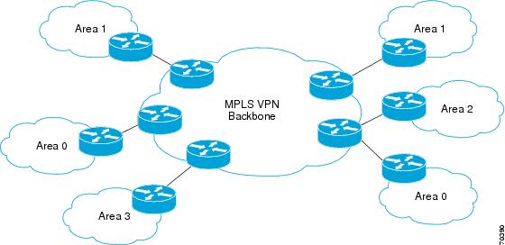
When OSPF is used to connect PE and CE routers, all routing information learned from a VPN site is placed in the VPN routing and forwarding (VRF) instance associated with the incoming interface. The PE routers that attach to the VPN use the BGP to distribute VPN routes to each other. A CE router can then learn the routes to other sites in the VPN by peering with its attached PE router. The MPLS VPN backbone provides an additional level of routing hierarchy to interconnect the VPN sites running OSPF.
When OSPF routes are propagated over the MPLS VPN backbone, additional information about the prefix in the form of BGP extended communities (route type, domain ID extended communities) is appended to the BGP update. This community information is used by the receiving PE router to decide the type of link-state advertisement (LSA) to be generated when the BGP route is redistributed to the OSPF PECE process. In this way, internal OSPF routes that belong to the same VPN and are advertised over the VPN backbone are seen as interarea routes on the remote sites.
OSPF Uses Backdoor Paths to Communicate Between VPN Sites
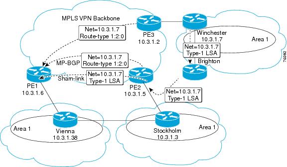
Although OSPF PECE connections assume that the only path between two client sites is across the MPLS VPN backbone, backdoor paths between VPN sites may exist. For instance, in the figure below, Vienna, Stockholm, Brighton, and Winchester can communicate through backdoor paths instead of using the MPLS VPN backbone.
If the sites belong to the same OSPF area, the backdoor path will always be selected, because OSPF prefers intra-area paths to interarea paths. (PE routers advertise OSPF routes learned over the VPN backbone as interarea paths.) For this reason, OSPF backdoor paths between VPN sites must be taken into account so that routing is performed based on policy.

For example, the figure above shows three client sites, each with backdoor links. Because each site runs OSPF within the same Area 1 configuration, all routing between the three sites uses the backdoor paths, rather than the MPLS VPN backbone.
The following example shows BGP routing table entries for the Winchester router (prefix 10.3.1.7/32) from the standpoint of the PE1 router in the figure. Prefix 10.3.1.7 is the loopback interface of the Winchester CE router. As shown in bold in this example, the loopback interface is learned via BGP from PE2 and PE3. It is also generated through redistribution into BGP on PE1.
PE1# show ip bgp vpnv4 all 10.3.1.7
BGP routing table entry for 100:251:10.3.1.7/32, version 58
Paths: (3 available, best #2)
  Advertised to non peer-group peers:
  10.3.1.2 10.3.1.5
  Local
    10.3.1.5 (metric 30) from 10.3.1.5 (10.3.1.5)
      Origin incomplete, metric 22, localpref 100, valid, internal
      Extended Community: RT:1:793 OSPF DOMAIN ID:0.0.0.100 OSPF
      RT:1:2:0 OSPF 2
  Local
    10.2.1.38 from 0.0.0.0 (10.3.1.6)
      Origin incomplete, metric 86, localpref 100, weight 32768,
      valid, sourced, best
      Extended Community: RT:1:793 OSPF DOMAIN ID:0.0.0.100 OSPF
      RT:1:2:0 OSPF 2
  Local
    10.3.1.2 (metric 30) from 10.3.1.2 (10.3.1.2)
      Origin incomplete, metric 11, localpref 100, valid, internal
      Extended Community: RT:1:793 OSPF DOMAIN ID:0.0.0.100 OSPF
      RT:1:2:0 OSPF 2
Within BGP, the locally generated route (10.2.1.38) is considered to be the best route.
However, as shown in bold in the next example, the VRF routing table shows that the selected path is learned via OSPF with a next hop of 10.2.1.38, which is the Vienna CE router.
PE1# show ip route vrf ospf 10.3.1.7
Routing entry for 10.3.1.7/32
  Known via "ospf 100", distance 110, metric 86, type intra area
  Redistributing via bgp 215
  Advertised by bgp 215
  Last update from 10.2.1.38 on Serial0/0/0, 00:00:17 ago
  Routing Descriptor Blocks:
  * 10.2.1.38
, from 10.3.1.7, 00:00:17 ago, via Serial0/0/0
      Route metric is 86, traffic share count is 1
This path is selected because:
- The OSPF backdoor path is preferred over the interarea path (over the MPLS VPN backbone) generated by the PE1 router.
- OSPF has a lower administrative distance (AD) than internal BGP (BGP running between routers in the same autonomous system).
If the backdoor paths between sites are used only for backup purposes and do not participate in the VPN service, then the default route selection is acceptable. You can set up the OSPF cost configured with a sham-link to send VPN site traffic over a backdoor path.
Sham-Links Direct Traffic Between VPN Sites over the MPLS VPN Backbone
To ensure that VPN sites that belong to the same OSPF area and share an OSPF backdoor path communicate with each other using the MPLS VPN backbone, you must create a sham-link. (If no backdoor path exists between the sites, no sham-link is required.) A sham-link is an additional OSPF intra-area (logical) link between ingress and egress VRFs on the PE routers that connect to the CE routers of the VPN sites.
The figure below shows a sample sham-link between PE1 and PE2. You associate a cost with each sham-link to force traffic to use the sham-link rather than the backdoor path. When a sham-link is configured between PE routers, the PE routers can populate the VRF routing table with the OSPF routes learned over the sham-link.
Because the sham-link is seen as an intra-area link between PE routers, an OSPF adjacency is created and database exchange (for the particular OSPF process) occurs across the link. The PE router can then flood LSAs between sites from across the MPLS VPN backbone. As a result, the desired intra-area connectivity is created.
How to Ensure That MPLS VPN Clients Communicate over the MPLS VPN Backbone
This section explains how to create a sham-link on an MPLS VPN PE router. Perform this task on both PE routers that share the sham-link.
Before you create a sham-link between PE routers in an MPLS VPN, you must:
- Configure a separate /32 address on the remote PE so that OSPF packets can be sent over the VPN backbone to the remote end of the sham-link. The /32 address must meet the following criteria:
You can use the /32 address for other sham-links.
DETAILED STEPS
Example
The following is sample output from the show ip ospf sham-links command:
Router# show ip ospf sham-links
Sham Link OSPF_SL0 to address 10.2.1.2 is up
Area 1 source address 10.2.1.1
  Run as demand circuit
  DoNotAge LSA allowed.
  Cost of using 40 State POINT_TO_POINT,
  Timer intervals configured,
  Hello 10, Dead 40, Wait 40,
    Hello due in 00:00:04
    Adjacency State FULL (Hello suppressed)
    Index 2/2, retransmission queue length 4,     number of retransmission 0
    First 0x63311F3C(205)/0x63311FE4(59) Next
    0x63311F3C(205)/0x63311FE4(59)
    Last retransmission scan length is 0,     maximum is 0
    Last retransmission scan time is 0 msec,     maximum is 0 msec
    Link State retransmission due in 360 msec
Configuration Examples for Ensuring MPLS VPN Clients Communicate over the MPLS VPN Backbone
The following example shows how to configure a sham-link between two PE routers:
Router1(config)# interface loopback 1
Router1(config-if)# ip vrf forwarding ospf
Router1(config-if)# ip address 10.2.1.1 255.255.255.255
!
Router2(config)# interface loopback 1
Router2(config-if)# ip vrf forwarding ospf
Router2(config-if)# ip address 10.2.1.2 255.255.255.255
!
Router1(config)# router ospf 100 vrf ospf
Router1(config-if)# area 1 sham-link 10.2.1.1 10.2.1.2 cost 40
!
Router2(config)# router ospf 100 vrf ospf
Router2(config-if)# area 1 sham-link 10.2.1.2 10.2.1.1 cost 40
This example shows how a sham-link is used only to affect the OSPF intra-area path selection of the PE and CE routers. The PE router also uses the information received from Multiprotocol BGP (MP-BGP) to set the outgoing label stack of incoming packets, and to decide to which egress PE router to label-switch the packets.
The figure below shows a sample MPLS VPN topology in which a sham-link configuration is necessary. A VPN client has three sites, each with a backdoor path. Two sham-links have been configured, one between PE1 and PE2, and another between PE2 and PE3. A sham-link between PE1 and PE3 is not necessary in this configuration, because the Vienna and Winchester sites do not share a backdoor path.
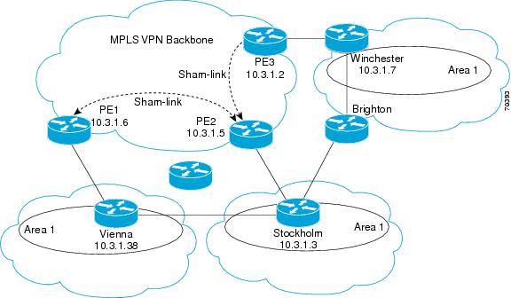
The following example shows the forwarding that occurs between sites from the standpoint of how PE1 views the 10.3.1.7/32 prefix, the loopback1 interface of the Winchester CE router in the figure above.
PE1# show ip bgp vpnv4 all 10.3.1.7
BGP routing table entry for 100:251:10.3.1.7/32, version 124
Paths: (1 available, best #1)
  Local
    10.3.1.2 (metric 30) from 10.3.1.2
 (10.3.1.2)
       Origin incomplete, metric 11, localpref 100, valid, internal,
       best
       Extended Community: RT:1:793 OSPF DOMAIN ID:0.0.0.100 OSPF
       RT:1:2:0 OSPF 2
PE1# show ip route vrf ospf 10.3.1.7
Routing entry for 10.3.1.7/32
  Known via "ospf 100
", distance 110, metric 13, type intra area
  Redistributing via bgp 215
  Last update from 10.3.1.2 00:12:59 ago
  Routing Descriptor Blocks:
10.3.1.2 (Default-IP-Routing-Table), from 10.3.1.7, 00:12:59 ago
The next example shows forwarding information in which the next hop for the route, 10.3.1.2, is the PE3 router rather than the PE2 router (which is the best path according to OSPF). The OSPF route is not redistributed to BGP on the PE, because the other end of the sham-link already redistributed the route to BGP and there is no need for duplication. The OSPF sham-link is used only to influence intra-area path selection. When sending traffic to a particular destination, the PE router uses the MP-BGP forwarding information.
PE1# show ip bgp vpnv4 all tag | begin 10.3.1.7
   10.3.1.7/32      10.3.1.2
        notag/38

PE1# show mpls forwarding 10.3.1.2
Local  Outgoing      Prefix           Bytes label    Outgoing   Next Hop
label  label or VC   or Tunnel Id     switched       interface
31     42            10.3.1.2/32
      0              PO3/0/0    point2point
PE1# show ip cef vrf ospf 10.3.1.7
10.3.1.7/32, version 73, epoch 0, cached adjacency to POS3/0/0
0 packets, 0 bytes
  tag information set
   local tag: VPN-route-head
   fast tag rewrite with PO3/0/0, point2point, tags imposed: {42 38
}
  via 10.3.1.2
, 0 dependencies, recursive
    next hop 10.1.1.17, POS3/0/0 via 10.3.1.2/32
    valid cached adjacency
    tag rewrite with PO3/0/0, point2point, tags imposed: {42 38}
If a prefix is learned across the sham-link and the path via the sham-link is selected as the best, the PE router does not generate an MP-BGP update for the prefix. It is not possible to route traffic from one sham-link over another sham-link.
In the following example, PE2 shows how an MP-BGP update for the prefix is not generated. Although 10.3.1.7/32 has been learned via OSPF across the sham-link as shown in bold, no local generation of a route into BGP is performed. The only entry within the BGP table is the MP-BGP update received from PE3 (the egress PE router for the 10.3.1.7/32 prefix).
PE2# show ip route vrf ospf 10.3.1.7
Routing entry for 10.3.1.7/32
  Known via "ospf 100
", distance 110, metric 12, type intra area
  Redistributing via bgp 215
  Last update from 10.3.1.2 00:00:10 ago
  Routing Descriptor Blocks:
  * 10.3.1.2 (Default-IP-Routing-Table), from 10.3.1.7, 00:00:10 ago
      Route metric is 12, traffic share count is 1
PE2# show ip bgp vpnv4 all 10.3.1.7
BGP routing table entry for 100:251:10.3.1.7/32, version 166
Paths: (1 available, best #1)
  Not advertised to any peer
  Local
    10.3.1.2 (metric 30) from 10.3.1.2 (10.3.1.2)
      Origin incomplete, metric 11, localpref 100, valid, internal,
      best
      Extended Community: RT:1:793 OSPF DOMAIN ID:0.0.0.100 OSPF
      RT:1:2:0 OSPF 2
The PE router uses the information received from MP-BGP to set the ongoing label stack of incoming packets, and to decide to which egress PE router to label-switch the packets.
Additional References
Related Documents
MIBs
RFCs
|
RFC |
Title |
|---|---|
|
RFC 1164 |
Application of the Border Gateway Protocol in the Internet |
|
RFC 1171 |
A Border Gateway Protocol 4 |
|
RFC 1700 |
Assigned Numbers |
|
RFC 1966 |
BGP Route Reflection: An Alternative to Full Mesh IBGP |
|
RFC 2283 |
Multiprotocol Extensions for BGP-4 |
|
RFC 2328 |
Open Shortest Path First, Version 2 |
|
RFC 2547 |
BGP/MPLS VPNs |
|
RFC 2842 |
Capabilities Advertisement with BGP-4 |
|
RFC 2858 |
Multiprotocol Extensions for BGP-4 |
|
RFC 3107 |
Carrying Label Information in BGP-4 |
Technical Assistance
|
Description |
Link |
|---|---|
|
The Cisco Technical Support website contains thousands of pages of searchable technical content, including links to products, technologies, solutions, technical tips, and tools. Registered Cisco.com users can log in from this page to access even more content. The Cisco Support website provides extensive online resources, including documentation and tools for troubleshooting and resolving technical issues with Cisco products and technologies. To receive security and technical information about your products, you can subscribe to various services, such as the Product Alert Tool (accessed from Field Notices), the Cisco Technical Services Newsletter, and Really Simple Syndication (RSS) Feeds. Access to most tools on the Cisco Support website requires a Cisco.com user ID and password. |
Feature Information for Ensuring MPLS VPN Clients Communicate over the MPLS VPN Backbone
The following table provides release information about the feature or features described in this module. This table lists only the software release that introduced support for a given feature in a given software release train. Unless noted otherwise, subsequent releases of that software release train also support that feature.
Use Cisco Feature Navigator to find information about platform support and Cisco software image support. To access Cisco Feature Navigator, go to www.cisco.com/go/cfn. An account on Cisco.com is not required.
| Table 1 | Feature Information for Ensuring MPLS VPN Clients Communicate over the MPLS VPN Backbone |
|
Feature Name |
Releases |
Feature Configuration Information |
|---|---|---|
|
Ensuring MPLS VPN Clients Communicate over the MPLS VPN Backbone |
12.2(8)T 12.0(21)ST 12.0(22)S |
This feature allows you to configure a sham-link that directs traffic between Virtual Private Network (VPN) client sites over the Multiprotocol Label Switching (MPLS) VPN backbone. |
Cisco and the Cisco logo are trademarks or registered trademarks of Cisco and/or its affiliates in the U.S. and other countries. To view a list of Cisco trademarks, go to this URL: www.cisco.com/go/trademarks. Third-party trademarks mentioned are the property of their respective owners. The use of the word partner does not imply a partnership relationship between Cisco and any other company. (1110R)
Any Internet Protocol (IP) addresses and phone numbers used in this document are not intended to be actual addresses and phone numbers. Any examples, command display output, network topology diagrams, and other figures included in the document are shown for illustrative purposes only. Any use of actual IP addresses or phone numbers in illustrative content is unintentional and coincidental.