
 Feedback
Contents
- Directing MPLS VPN Traffic Using a Source IP Address
- Finding Feature Information
- Prerequisites for Directing MPLS VPN Traffic Using a Source IP Address
- Restrictions for Directing MPLS VPN Traffic Using a Source IP Address
- Information About Directing MPLS VPN Traffic Using a Source IP Address
- Introduction to Directing MPLS VPN Traffic Using a Source IP Address
- How MPLS VPN Traffic Is Routed Using the Source IP Address
- Example of MPLS VPN Traffic Being Routed Based on the Source IP Address
- MPLS VPN Traffic Is Unidirectional
- Conditions That Cause MPLS VPN Traffic To Become Bidirectional
- Advantages of Using the Source IP Address over Per-Interface IP VPN Configuration
- Benefits of Directing MPLS VPN Traffic Using a Source IP Address
- How to Enable MPLS VPN Traffic To Be Routed Using a Source IP Address
- Enabling Routing of MPLS VPN Traffic Based on the Source IP Address
- Establishing IP Static Routes for a VRF Instance
- Troubleshooting Tips
- Configuration Examples for Directing MPLS VPN Traffic Using a Source IP Address
- Enabling MPLS VPN Traffic To Be Routed Based on Source IP Address Example
- Configuring a VRF to Eliminate Unnecessary Packet Forwarding Example
- Verifying the Configuration Example
- Additional References
- Feature Information for Directing MPLS VPN Traffic Using a Source IP Address
Directing MPLS VPN Traffic Using a Source IP Address
This module explains how to set up an interface on a provider edge (PE) router to route packets to different Multiprotocol Label Switching (MPLS) Virtual Private Networks (VPNs) based on the source IP address of the packet.
- Finding Feature Information
- Prerequisites for Directing MPLS VPN Traffic Using a Source IP Address
- Restrictions for Directing MPLS VPN Traffic Using a Source IP Address
- Information About Directing MPLS VPN Traffic Using a Source IP Address
- How to Enable MPLS VPN Traffic To Be Routed Using a Source IP Address
- Configuration Examples for Directing MPLS VPN Traffic Using a Source IP Address
- Additional References
- Feature Information for Directing MPLS VPN Traffic Using a Source IP Address
Finding Feature Information
Your software release may not support all the features documented in this module. For the latest feature information and caveats, see the release notes for your platform and software release. To find information about the features documented in this module, and to see a list of the releases in which each feature is supported, see the Feature Information Table at the end of this document.
Use Cisco Feature Navigator to find information about platform support and Cisco software image support. To access Cisco Feature Navigator, go to www.cisco.com/go/cfn. An account on Cisco.com is not required.
Prerequisites for Directing MPLS VPN Traffic Using a Source IP Address
- MPLS VPNs must be enabled in the provider network.
- Cisco Express Forwarding (CEF) must be enabled on any interfaces that have this feature enabled.
- The Cisco IOS software must support MPLS VPNs, and the provider network must have MPLS Label Distribution Protocol (LDP) installed and running.
- This feature is supported on the Cisco 7200 series, 7500 series, and 12000 series router platforms.
Restrictions for Directing MPLS VPN Traffic Using a Source IP Address
VRF Select is supported only in Service Provider (-p-) images.
Unidirectional Traffic
This is a unidirectional feature and can only be used from a customer (IP-based) network into a provider (MPLS-based) network. This feature cannot be used from a provider network to a customer network.
Subnet Masks
Subnet masks should be kept as short as possible for Engine 2 line cards. Performance can degrade with longer subnet masks (/24 or /32, for example).
traceroute Command
An IP traceroute command from a customer edge (CE) router that has this featue enabled to a typical MPLS VPN VRF CE router works as expected. However, an IP traceroute command from a typical MPLS VPN VRF CE router to a CE router that has this feature enabled may fail to show all the relevant hop information across the core.
Supported Static Route Configurations
When configuring static routes in an MPLS or MPLS VPN environment, some variations of the ip route and ip route vrf commands are not supported. These variations of the commands are not supported in Cisco IOS releases that support the Tag Forwarding Information Base (TFIB), specifically Cisco IOS Releases 12.xT, 12.xM, and 12.0S. The TFIB cannot resolve prefixes when the recursive route over which the prefixes travel disappears and then reappears. However, the command variations are supported in Cisco IOS releases that support the MPLS Forwarding Infrastructure (MFI), specifically Cisco IOS Release 12.2(25)S and later. Use the following guidelines when configuring static routes.
Supported Static Routes in an MPLS Environment
The following ip route command is supported when you configure static routes in MPLS environment:
ip route destination-prefix mask interface next-hop-address
The following ip route commands are supported when you configure static routes in an MPLS environment and configure load sharing with static nonrecursive routes and a specific outbound interface:
ip route destination-prefix mask interface1 next-hop1
ip route destination-prefix mask interface2 next-hop2
Unsupported Static Routes in an MPLS Environment that Uses the TFIB
The following ip route command is not supported when you configure static routes in an MPLS environment:
ip route destination-prefix mask next-hop-address
The following ip route command is not supported when you configure static routes in an MPLS environment and enable load sharing where the next hop can be reached through two paths:
ip route destination-prefix mask next-hop-address
The following ip route command is not supported when you configure static routes in an MPLS environment and enable load sharing where the destination can be reached through two next hops:
ip route destination-prefix mask next-hop1
ip route destination-prefix mask next-hop2
Use the interface and next-hop arguments when specifying static routes.
Supported Static Routes in an MPLS VPN Environment
The following ip route vrf commands are supported when you configure static routes in a MPLS VPN environment, and the next hop and interface are in the same VRF:
The following ip route vrf commands are supported when you configure static routes in a MPLS VPN environment, and the next hop is in the global table in the MPLS cloud in the global routing table. For example, these commands are supported when the next hop is pointing to the Internet Gateway.
The following ip route commands are supported when you configure static routes in a MPLS VPN environment and enable load sharing with static nonrecursive routes and a specific outbound interfaces:
ip route destination-prefix mask interface1 next-hop1
ip route destination-prefix mask interface2 next-hop2
Unsupported Static Routes in an MPLS VPN Environment that Uses the TFIB
The following ip route command is not supported when you configure static routes in a MPLS VPN environment, the next hop is in the global table in the MPLS cloud within the core, and you enable load sharing where the next hop can be reached through two paths:
ip route vrf destination-prefix mask next-hop-address global
The following ip route commands are not supported when you configure static routes in a MPLS VPN environment, the next hop is in the global table in the MPLS cloud within the core, and you enable load sharing where the destination can be reached through two next hops:
ip route vrf destination-prefix mask next-hop1 global
ip route vrf destination-prefix mask next-hop2 global
The following ip route vrf commands are not supported when you configure static routes in an MPLS VPN environment, and the next hop and interface are in the same VRF:
ip route vrf vrf-name destination-prefix mask next-hop1
ip route vrf vrf-name destination-prefix mask next-hop2
Supported Static Routes in an MPLS VPN Environment Where the Next Hop Resides in the Global Table on the CE Router
The following ip route vrf command is supported when you configure static routes in a MPLS VPN environment, and the next hop is in the global table on the CE side. For example, the following command is supported when the destination-prefix is the CE router's loopback address, as in EBGP multihop cases.
ip route vrf vrf-name destination-prefix mask interface next-hop-address
The following ip route commands are supported when you configure static routes in a MPLS VPN environment, the next hop is in the global table on the CE side, and you enable load sharing with static non-recursive routes and a specific outbound interfaces:
ip route destination-prefix mask interface1 nexthop1
ip route destination-prefix mask interface2 nexthop2
Information About Directing MPLS VPN Traffic Using a Source IP Address
- Introduction to Directing MPLS VPN Traffic Using a Source IP Address
- How MPLS VPN Traffic Is Routed Using the Source IP Address
- Example of MPLS VPN Traffic Being Routed Based on the Source IP Address
- MPLS VPN Traffic Is Unidirectional
- Advantages of Using the Source IP Address over Per-Interface IP VPN Configuration
- Benefits of Directing MPLS VPN Traffic Using a Source IP Address
Introduction to Directing MPLS VPN Traffic Using a Source IP Address
This feature allows packets arriving on an interface to be switched into the appropriate VRF table based upon the source IP address of the packets. Once the packets have been "selected" into the correct VRF routing table, they are processed normally based upon the destination address and forwarded through the rest of the MPLS VPN.
In most cases, this is a "one way" feature; it works on packets coming from the end users to the PE router.
How MPLS VPN Traffic Is Routed Using the Source IP Address
This feature uses the following process to route packets from the customer networks to the PE router and into the provider network.
A two-table lookup mechanism is used at the ingress interface of the PE router to determine the routing and forwarding of packets coming from the customer networks, which use IP protocols, to the MPLS VPN networks, which use MPLS protocols.
- The first table, the VRF Selection table, is used to compare the source IP address of the packet with a list of IP addresses in the table. Each IP address in the table is associated with an MPLS VPN. If a match is found between the source IP address of the packet and an IP address in the VRF Selection table, the packet is routed to the second table (the VRF table) or the routing table for the appropriate VPN.
If no match is found in the table for the source IP address of the packet, the packet will either be routed via the global routing table used by the PE router (this is the default behavior), or will be dropped. See the Configuring a VRF to Eliminate Unnecessary Packet Forwarding Example for more information.
- The second table, the VRF table (also known as the VPN routing and forwarding table), contains the virtual routing and forwarding information for the specified VPN and is used to forward the selected VPN traffic to the correct MPLS label switched path (LSP) based upon the destination IP address of the packet.
The VRF Selection process removes the association between the VRF and the interface and allows more than one MPLS VPN VRF to be associated with the interface.
Example of MPLS VPN Traffic Being Routed Based on the Source IP Address
An example of this feature is a network carrier that allows subscribers to the carrier to choose from multiple Internet service providers (ISPs) for Internet access. The figure below provides an example of this feature with an IP-based Host network, an MPLS VPN network, and three ISPs connected to the MPLS VPN network.
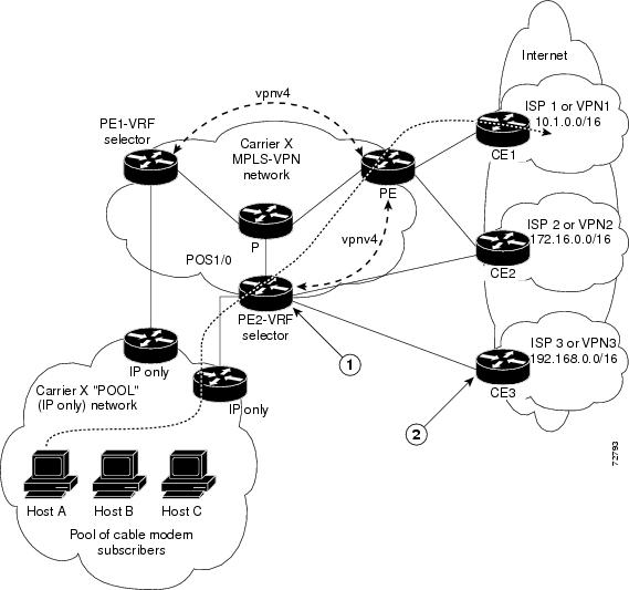
In the figure above, Carrier X represents the network carrier; Host A, Host B and Host C represent the carrier subscribers; and ISP 1, ISP 2 and ISP 3 represent the ISPs.
- PE2 acts as both a VRF selector and a typical MPLS VPN PE router to CE2 and CE3.
- ISPs 1 through 3 provide a list of IP addresses to Carrier X so that each host in the "POOL" network can be properly addressed. This host addressing would most likely be done by using the DHCP or DNS services of Carrier X.
A dashed line represents the path of a packet traveling from Host A to ISP 1. Host A chooses ISP 1 to use as its ISP. Carrier X provides an IP address to Host A that falls within the range of the ISP 1 registered network addresses (1.1.0.0/16). Based upon this IP address allocation, the VRF Selection criteria is set.
By using default routes, hosts on the POOL network (such as Host A), forward traffic from the Carrier X IP-based (POOL) network to the Carrier X MPLS-based VPN network. PE2 has been configured with this feature. Therefore, the MPLS VPN network forwards the traffic from Host A to ISP 1.
This is a one-way (unidirectional) feature in most implementations; it only works on packets coming from the customer networks to a PE router. Traffic coming from the ISPs to the hosts (in the example, traffic traveling from the ISPs on the right to the hosts on the left) is not affected by this feature and does not have to be returned via an MPLS path. This traffic can return via the shortest available IP path.
Another example is a Cable Modem Termination System (CMTS). If the owner of the CMTS wants to allow cable modem subscribers to choose their ISP from a group of ISPs, this feature provides a fast and scalable solution.
MPLS VPN Traffic Is Unidirectional
In the figure above, the end users are typical Internet home users. If this were a two-way (bidirectional) feature, traffic coming from the ISPs to the hosts would be required to use only the PE routers that have this feature enabled, which might cause performance issues.
When traffic from the POOL network goes through the Carrier network to the ISP networks for Internet access, the traffic in the Carrier network must be forwarded using MPLS VPN paths, because the router has "selected" the traffic into the correct MPLS VPN.
Traffic from the ISP networks to the POOL network does not have to use MPLS VPN paths in the Carrier network and can use any path that is most efficient to return to the POOL network. This traffic can use a path that uses either MPLS or IP for routing and forwarding and does not have to travel via an MPLS VPN.
Traffic from the ISP networks to the POOL networks can be forwarded using the global routing table used by every interface. One way to accomplish this is to enter VRF static routes on the PE router interfaces connected to the ISPs. The VRF static routes would route traffic from the ISPs to the Carrier network. See the Establishing IP Static Routes for a VRF Instance for information on placing a default VRF static route onto an interface.
Establishing static VRF routes allows traffic from the ISPs to enter the Carrier network as traffic that can only be routed by using the global routing table toward the POOL network.
If the ISPs do not provide global host address space, or this feature is not being used to route Internet traffic, the PE interfaces connected to the ISPs must be placed into a VRF. If the PE interfaces are using VRFs for routing traffic from the ISPs, all traffic from the ISPs to the hosts through the Carrier network would be forwarded using MPLS VPN paths, and performance would not be as optimal as if IP forwarding was used.
Normal IP-based VPN operations, such as populating the Routing Information Base (RIB) and Forwarding Information Base (FIB) from a routing protocol such as Border Gateway Protocol (BGP), are used to route and forward packets within the various VPNs in the customer networks. The provider network uses MPLS-based routing protocols to perform VPN routing and forwarding inside the provider network.
Conditions That Cause MPLS VPN Traffic To Become Bidirectional
Forwarding of traffic from the Carrier network to the POOL network by using the global routing table is only possible if the ISPs have provided registered IP address space for all of the subscribed users within the POOL network from the global routing table.
If the POOL network uses IP addresses that are not globally routeable and are designed for a nonconnected enterprise (defined by RFC 1918), this feature becomes bidirectional. All traffic being sent and received by the host would have to travel via a router that has this feature enabled. The POOL network cannot be addressed with overlapping address space, regardless of the type of address space being used.
Advantages of Using the Source IP Address over Per-Interface IP VPN Configuration
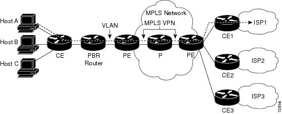
This feature removes the association between a VPN and an interface. Before this feature was introduced, the following implementation was used to route outgoing MPLS VPN packets to different destinations:
- A policy-based router (PBR) is attached to the CE router.
- The egress side of the PBR router side has VLANs connected to a PE.
- The PBR router uses a policy-based route map to select the correct output (VLAN) interface and each VLAN is under a specific VRF. The figure below illustrates a sample configuration of using a PBR router for routing MPLS packets to different destinations.
The following limitations apply to PBR-based solutions that use this implementation:
- Policy routing and MPLS VPN functions cannot be performed on the same platform. Integration into a single platform is critical for manageability and support.
- VRF is limited to one VPN per interface, which limits scalability.
- The Cisco 7500 series router is used for the PBR, which can limit network performance.
- There is no network redundancy.
- The PBR is the only point of connection for all the networks attached to the PBR. The capacity and the performance capabilities of the PBR router are critical.
- There is no diversity in the connectivity to the networks.
- Every network is required to connect to every PBR. If every network is not connected to every PBR, packets from the end user to the PBR would be dropped because the PBR would have no way of switching the IP traffic properly.
- Adding multiple PBRs that are interconnected introduces more network policy-routed hops.
This feature addresses the limitations of and problems with using a PBR for packet routing and forwarding.
Benefits of Directing MPLS VPN Traffic Using a Source IP Address
Association of VPN to interface is removed
This feature removes the association between a VPN and an interface, thus allowing packets from the Host network to the provider network to have more than one VPN available per interface.
How to Enable MPLS VPN Traffic To Be Routed Using a Source IP Address
- Enabling Routing of MPLS VPN Traffic Based on the Source IP Address
- Establishing IP Static Routes for a VRF Instance
Enabling Routing of MPLS VPN Traffic Based on the Source IP Address
DETAILED STEPS
Establishing IP Static Routes for a VRF Instance
Traffic coming from the ISPs to the hosts does not require the use of the MPLS VPN paths; this traffic can use the shortest IP route back to the host.
VPN static routes for traffic returning to the customer networks are only necessary if VPN traffic returning to the customer networks is being forwarded back from the enabled interface. The remote PE router could also be configured to route return traffic to the customer networks directly by using the global routing table.
DETAILED STEPS
Troubleshooting Tips
 Note | The debug vrf select command can cause many messages to be logged when you change the configuration and when switching occurs. |
- The following error messages appear if problems occur while configuring this feature:
Router(config)# vrf selection source 2.0.0.0o 255.255.0.0 vrf VRF_NOEXIST
VRF Selection: VRF table VRF_NOEXIST does not exist.
Router(config)# no vrf selection source 2.0.0.0 255.255.0.0 vrf VRF1
VRF Selection: Can't find the node to remove.
Router(config)# vrf selection source 2.0.0.0 255.0.0.0 vrf VRF_AOL
Router(config)# vrf selection source 2.0.0.0 255.0.0.0 vrf VRF_AOL
VRF Selection: duplicate address and mask configured.
Router(config)# vrf selection source 170.1.2.1 255.255.255.0 vrf red
% Inconsistent address and mask
Router(config)# vrf selection source 170.1.2.1 255.255.255.255 vrf red
- If you attempt to configure a VRF instance on an interface that has this feature already configured:
Router(config-if)# ip vrf select source
Router(config-if)# ip vrf forward red
% Can not configure VRF if VRF Select is already configured
To enable VRF, first remove VRF Select from the interface
Router(config-if)# ip vrf forward red
Router(config-if)# ip vrf select source
% Can not configure VRF Select if interface is under a non-global VRF
To enable VRF Select, first remove VRF from the interface
Configuration Examples for Directing MPLS VPN Traffic Using a Source IP Address
- Enabling MPLS VPN Traffic To Be Routed Based on Source IP Address Example
- Configuring a VRF to Eliminate Unnecessary Packet Forwarding Example
- Verifying the Configuration Example
Enabling MPLS VPN Traffic To Be Routed Based on Source IP Address Example
The following example defines two entries (vpn1 and vpn2) in the VRF Selection table. In this example, packets with the source address of 16.16.0.0 will be routed to the VRF vpn1, and packets with the source address of 17.17.0.0 will be routed to the VRF vpn2:
Router(config)# vrf selection source 16.16.0.0 255.255.0.0 vrf vpn1
Router(config)# vrf selection source 17.17.0.0 255.255.0.0 vrf vpn2
The following example creates IP static routes for two VRFs (vpn1 and vpn2) for the POS1/0 interface:
Router(config)# ip route vrf vpn1 16.16.0.0 255.255.0.0 POS1/0
Router(config)# ip route vrf vpn1 17.17.0.0 255.255.0.0 POS1/0
The following example configures the POS1/0 interface for this feature and adds the configured IP address (31.0.0.1) to the VRFs vpn1 and vpn2 as connected routes.
Router(config)# interface POS1/0
Router(config-if)# description Link to CE1 POS1/0 (eng2)
Router(config-if)# ip vrf select source
Router(config-if)# ip vrf receive vpn1
Router(config-if)# ip vrf receive vpn2
Router(config-if)# ip address 31.0.0.1 255.0.0.0
Router(config-if)# no ip directed broadcast
Router(config-if)# load-interval 30
Router(config-if)# crc 32
Router(config-if)# end
Configuring a VRF to Eliminate Unnecessary Packet Forwarding Example
If a packet arrives at an interface that has VRF Select enabled, and its source IP address does not match any VRF Select definition, that packet will be forwarded via the global routing table. This default behavior could cause problems if IP address spoofing is being implemented. Unnecessary traffic could be forwarded via the global routing table. To eliminate this unnecessary routing of packets, create a VRF Selection definition that will forward all unknown incoming traffic to a null interface.
The following configuration causes all traffic not matching a more specific VRF Selection definition to be routed to the Null0 interface, thus dropping the packets.
Router(config)# ip vrf VRF_DROP
Router(config-vrf)# rd 999:99
Router(config-vrf)# route-target export 999:99
Router(config-vrf)# route-target import 999:99
Router(config-vrf)# exit
Router(config)# vrf selection source 0.0.0.0 0.0.0.0 vrf VRF_DROP
Router(config)# ip route vrf VRF_DROP 0.0.0.0 0.0.0.0 Null0
Verifying the Configuration Example
This example shows the IP routing table associated with the VRF vrf1:
Router# show ip route vrf vpn1
Routing Table: vpn1
Codes: C - connected, S - static, I - IGRP, R - RIP, M - mobile, B - BGP
D - EIGRP, EX - EIGRP external, O - OSPF, IA - OSPF inter area
N1 - OSPF NSSA external type 1, N2 - OSPF NSSA external type 2
E1 - OSPF external type 1, E2 - OSPF external type 2, E - EGP
i - IS-IS, L1 - IS-IS level-1, L2 - IS-IS level-2, ia - IS-IS inter area
* - candidate default, U - per-user static route, o - ODR
Gateway of last resort is not set
B    33.0.0.0/8 [200/0] via 10.10.10.10, 00:00:37
5.0.0.0/16 is subnetted, 1 subnets
B       5.19.0.0 [200/0] via 10.10.10.10, 00:00:37
14.0.0.0/32 is subnetted, 1 subnets
B       14.14.14.14 [200/0] via 10.10.10.10, 00:00:37
15.0.0.0/32 is subnetted, 1 subnets
S       15.15.15.15 [1/0] via 34.0.0.1, POS1/1
Additional References
Related Documents
MIBs
|
MIB |
MIBs Link |
|---|---|
|
No new or modified MIBs are supported by this feature, and support for existing MIBs has not been modified by this feature. |
To obtain lists of supported MIBs by platform and Cisco software release, and to download MIB modules, go to the Cisco MIB website on Cisco.com at the following URL: http://www.cisco.com/public/sw-center/netmgmt/cmtk/mibs.shtml |
Technical Assistance
|
Description |
Link |
|---|---|
|
The Cisco Technical Support website contains thousands of pages of searchable technical content, including links to products, technologies, solutions, technical tips, and tools. Registered Cisco.com users can log in from this page to access even more content. The Cisco Support website provides extensive online resources, including documentation and tools for troubleshooting and resolving technical issues with Cisco products and technologies. To receive security and technical information about your products, you can subscribe to various services, such as the Product Alert Tool (accessed from Field Notices), the Cisco Technical Services Newsletter, and Really Simple Syndication (RSS) Feeds. Access to most tools on the Cisco Support website requires a Cisco.com user ID and password. |
Feature Information for Directing MPLS VPN Traffic Using a Source IP Address
The following table provides release information about the feature or features described in this module. This table lists only the software release that introduced support for a given feature in a given software release train. Unless noted otherwise, subsequent releases of that software release train also support that feature.
Use Cisco Feature Navigator to find information about platform support and Cisco software image support. To access Cisco Feature Navigator, go to www.cisco.com/go/cfn. An account on Cisco.com is not required.
| Table 1 | Feature Information for Directing MPLS VPN Traffic Using a Source IP Address |
|
Feature Name |
Releases |
Feature Configuration Information |
|---|---|---|
|
VRF Selection Based on Source IP Address |
12.0(22)S 12.0(23)S 12.0(24)S 12.0(26)S |
This feature lets you direct MPLS VPN traffic based on the source IP address of the packet. |
Cisco and the Cisco logo are trademarks or registered trademarks of Cisco and/or its affiliates in the U.S. and other countries. To view a list of Cisco trademarks, go to this URL: www.cisco.com/go/trademarks. Third-party trademarks mentioned are the property of their respective owners. The use of the word partner does not imply a partnership relationship between Cisco and any other company. (1110R)
Any Internet Protocol (IP) addresses and phone numbers used in this document are not intended to be actual addresses and phone numbers. Any examples, command display output, network topology diagrams, and other figures included in the document are shown for illustrative purposes only. Any use of actual IP addresses or phone numbers in illustrative content is unintentional and coincidental.