
 Feedback
Contents
- L2VPN Multisegment Pseudowires
- Finding Feature Information
- Prerequisites for L2VPN Multisegment Pseudowires
- Restrictions for L2VPN Multisegment Pseudowires
- Information About L2VPN Multisegment Pseudowires
- L2VPN Pseudowire Defined
- L2VPN Multisegment Pseudowire Defined
- MPLS OAM Support for Multisegment Pseudowires
- MPLS OAM Support for L2VPN VPLS Inter-AS Option B
- How to Configure L2VPN Multisegment Pseudowires
- Configuring L2VPN Multisegment Pseudowires
- Cisco 7600 Router-Specific Instructions
- Displaying Information About the L2VPN Multisegment Pseudowires
- Verifying Multisegment Pseudowires with ping mpls and trace mpls Commands
- Verifying L2VPN VPLS Inter-AS Option B with ping mpls and trace mpls Commands
- Configuration Examples for L2VPN Multisegment Pseudowires
- Example Configuring an L2VPN Multisegment Pseudowire
- Additional References
- Feature Information for L2VPN Multisegment Pseudowires
L2VPN Multisegment Pseudowires
The L2VPN Multisegment Pseudowires feature enables you to configure two or more Layer 2 pseudowire segments that function as a single pseudowire. Layer 2 Virtual Private Network (L2VPN) multisegment pseudowires span multiple cores or autonomous systems of the same or different carrier networks. L2VPN multisegment pseudowires are also used in L2VPN Virtual Private LAN Services (VPLS) Inter-AS Option B networks.
This document explains Multiprotocol Label Switching (MPLS) Operations, Administration, and Maintenance (OAM) Support for L2VPN Multisegment Pseudowires and the MPLS OAM Support for the L2VPN VPLS Inter-AS Option B feature. These features allow you to use ping mpls and trace mpls commands to ensure pseudowire connectivity.
- Finding Feature Information
- Prerequisites for L2VPN Multisegment Pseudowires
- Restrictions for L2VPN Multisegment Pseudowires
- Information About L2VPN Multisegment Pseudowires
- How to Configure L2VPN Multisegment Pseudowires
- Configuration Examples for L2VPN Multisegment Pseudowires
- Additional References
- Feature Information for L2VPN Multisegment Pseudowires
Finding Feature Information
Your software release may not support all the features documented in this module. For the latest caveats and feature information, see Bug Search Tool and the release notes for your platform and software release. To find information about the features documented in this module, and to see a list of the releases in which each feature is supported, see the feature information table at the end of this module.
Use Cisco Feature Navigator to find information about platform support and Cisco software image support. To access Cisco Feature Navigator, go to www.cisco.com/go/cfn. An account on Cisco.com is not required.
Prerequisites for L2VPN Multisegment Pseudowires
Restrictions for L2VPN Multisegment Pseudowires
- Only Multiprotocol Label Switching (MPLS) Layer 2 pseudowires are supported.
- In Cisco IOS Release 12.3(33)SRE, only static configuration of the pseudowires is supported for the L2VPN Multisegment Pseudowires feature.
- In Cisco IOS Release 15.1(1)S, dynamic configuration of the pseudowires is supported and required for the L2VPN VPLS Inter-AS Option B feature.
- In Cisco IOS Release 12.3(33)SRE, only pseudowires advertised with forwarding equivalence class (FEC) 128 are supported for the L2VPN Multisegment Pseudowires feature. FEC 129 is not supported.
- In Cisco IOS Release 15.1(1)S, FEC 129 is supported and used to exchange information about the pseudowires for the L2VPN VPLS Inter-AS Option B feature.
- The S-PE router is limited to 1600 pseudowires.
Information About L2VPN Multisegment Pseudowires
- L2VPN Pseudowire Defined
- L2VPN Multisegment Pseudowire Defined
- MPLS OAM Support for Multisegment Pseudowires
- MPLS OAM Support for L2VPN VPLS Inter-AS Option B
L2VPN Pseudowire Defined
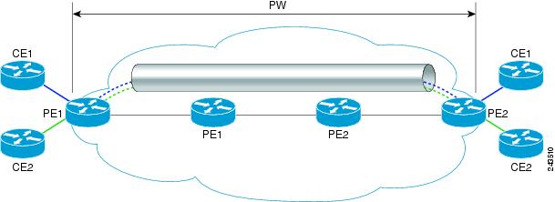
An L2VPN pseudowire (PW) is a tunnel established between two provider edge (PE) routers across the core carrying the Layer 2 payload encapsulated as MPLS data, as shown in the figure below. This helps carriers migrate from traditional Layer 2 networks such as Frame Relay and ATM to an MPLS core. The PWs between two PE routers are located within the same autonomous system (AS). Routers PE1 and PE2 are called terminating PE routers (T-PEs). Attachment circuits are bounded to the PW on these PE routers.
L2VPN Multisegment Pseudowire Defined
An L2VPN multisegment pseudowire (MS-PW) is a set of two or more PW segments that function as a single PW, as shown in the figure below. It is also known as switched PW. MS-PWs span multiple cores or autonomous systems of the same or different carrier networks. An L2VPN MS-PW can include up to 254 PW segments.
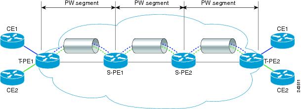
The end routers are called terminating PE routers (T-PEs), and the switching routers are called S-PE routers. The S-PE router terminates the tunnels of the preceding and succeeding PW segments in an MS-PW. The S-PE router can switch the control and data planes of the preceding and succeeding PW segments of the MS-PW. An MS-PW is declared to be up when all the single-segment PWs are up. For more information, see the L2VPN Pseudowire Switching document.
With the L2VPN Multisegment Pseudowire feature introduced in Cisco IOS Release 12.2(33)SRE, the pseudowires are created statically, and FEC 128 information is used to exchange the information about each AS.
MPLS OAM Support for Multisegment Pseudowires
You can use the ping mpls and trace mplscommands to verify that all the segments of the MPLS multisegment pseudowire are operating.
You can use the ping mpls command to verify connectivity at the following pseudowire points:
- From one end of the pseudowire to the other
- From one of the pseudowires to a specific segment
- The segment between two adjacent S-PE routers
You can use the trace mplscommand to verify connectivity at the following pseudowire points:
- From one end of the pseudowire to the other
- From one of the pseudowires to a specific segment
- The segment between two adjacent S-PE routers
- A range of segments
MPLS OAM Support for L2VPN VPLS Inter-AS Option B
The L2VPN VPLS Inter-AS Option B feature introduced in Cisco IOS Release 15.1(1)S uses multisegment pseudowires to connect Autonomous System Border Routers (ASBRs) in different autonomous systems. With this feature, the pseudowires are created dynamically, and FEC 129 information is used to exchange the information about each ASBR.
The differences between static multisegment pseudowires and dynamic multisegment pseudowires are listed in the table below.
| Table 1 | Comparison of Static and Dynamic Multisegment Pseudowires |
|
Static Multisegment Pseudowires |
Dynamic Multisegment Pseudowires |
|---|---|
|
Are statically stitched and dynamically signalled. |
Are dynamically stitched and dynamically signalled. |
|
Label Distribution Protocol (LDP) exchanges the type length value (TLV) and FEC 128 information is exchanged between segments. |
Border Gateway Protocol (BGP) exchanges the TLV and FEC 129 information is exchanged between ASBRs. |
For more information about the L2VPN VPLS Inter-AS Option B feature, see L2VPN VPLS Inter-AS Option B.
How to Configure L2VPN Multisegment Pseudowires
- Configuring L2VPN Multisegment Pseudowires
- Displaying Information About the L2VPN Multisegment Pseudowires
- Verifying Multisegment Pseudowires with ping mpls and trace mpls Commands
- Verifying L2VPN VPLS Inter-AS Option B with ping mpls and trace mpls Commands
Configuring L2VPN Multisegment Pseudowires
Perform the following steps on the S-PE routers to create L2VPN multisegment pseudowires.
Cisco 7600 Router-Specific Instructions
If the Cisco 7600 router is the penultimate hop router connected to the S-PE or T-PE router, issue the following commands on the S-PE or T-PE routers:
- mpls ldp explicit-null
- no mls mpls explicit-null propagate-ttl
DETAILED STEPS
Displaying Information About the L2VPN Multisegment Pseudowires
DETAILED STEPS
| Step 1 |
show
mpls
l2transport
binding
Use the show mpls l2transport binding command to display information about the pseudowire switching point, as shown in bold in the output. (In the following examples PE1 and PE4 are the T-PE routers.) Example: Router# show mpls l2transport binding Destination Address: 10.1.1.1, VC ID: 102 Local Label: 17 Cbit: 1, VC Type: Ethernet, GroupID: 0 MTU: 1500, Interface Desc: n/a VCCV: CC Type: CW [1], RA [2], TTL [3] CV Type: LSPV [2] Remote Label: 16 Cbit: 1, VC Type: Ethernet, GroupID: 0 MTU: 1500, Interface Desc: n/a VCCV: CC Type: CW [1], RA [2], TTL [3] CV Type: LSPV [2] PW Switching Point: Vcid local IP addr remote IP addr Description 101 10.11.11.11 10.20.20.20 PW Switching Point PE3 100 10.20.20.20 10.11.11.11 PW Switching Point PE2 |
| Step 2 |
show
mpls
l2transport
vc
detail
Use the show mpls l2transport vc detail command to display status of the pseudowire switching point. In the following example, the output (shown in bold) displays the segment that is the source of the fault of the multisegment pseudowire: Example: Router# show mpls l2transport vc detail Local interface: Se3/0 up, line protocol up, HDLC up Destination address: 12.1.1.1, VC ID: 100, VC status: down Output interface: Se2/0, imposed label stack {23} Preferred path: not configured Default path: active Next hop: point2point Create time: 00:03:02, last status change time: 00:01:41 Signaling protocol: LDP, peer 10.1.1.1:0 up Targeted Hello: 10.1.1.4(LDP Id) -> 10.1.1.1, LDP is UP Status TLV support (local/remote) : enabled/supported LDP route watch : enabled Label/status state machine : established, LruRrd Last local dataplane status rcvd: No fault Last local SSS circuit status rcvd: No fault Last local SSS circuit status sent: DOWN(PW-tx-fault) Last local LDP TLV status sent: No fault Last remote LDP TLV status rcvd: DOWN(PW-tx-fault) PW Switching Point: Fault type Vcid local IP addr remote IP addr Description PW-tx-fault 101 10.1.1.1 10.1.1.1 S-PE2 Last remote LDP ADJ status rcvd: No fault MPLS VC labels: local 19, remote 23 Group ID: local 0, remote 0 MTU: local 1500, remote 1500 Remote interface description: Sequencing: receive disabled, send disabled VC statistics: packet totals: receive 16, send 27 byte totals: receive 2506, send 3098 packet drops: receive 0, seq error 0, send 0 |
Verifying Multisegment Pseudowires with ping mpls and trace mpls Commands
You can use ping mpls and trace mpls commands to verify connectivity in multisegment pseudowires.
 Note | Some ping mpls and trace mplskeywords that are available with IPv4 LDP or traffic engineering (TE) are not available with pseudowire. The following keywords are not available with the ping mpls pseudowire command: The following keywords are not available with the trace mpls pseudowire command: > |
DETAILED STEPS
| Step 1 |
ping
mpls
pseudowire
destination-address
vc-id
[segment
segment-number]
Where:
The following examples use the topology shown in the second figure above:
ping mpls pseudowire destination-address vc-id
ping mpls pseudowire destination-address vc-id segment 2 Example: |
| Step 2 |
trace
mpls
pseudowire
destination-address
vc-id
segment
segment-number
[segment-number
]
Where:
The following examples use the topology shown in the second figure above:
trace mpls pseudowire destination-address vc-id segment 2 This example performs a trace from T-PE1 to S-PE2.
trace mpls pseudowire destination-address vc-id segment 2 4 The following commands perform trace operations on S-PE router 10.10.10.9, first on segment 1, then on segment 2. Segment 1 trace: Example: Router# trace mpls pseudowire 10.10.10.9 220 segment 1 Tracing MS-PW segments within range [1-1] peer address 10.10.10.9 and timeout 2 seconds Codes: '!' - success, 'Q' - request not sent, '.' - timeout, 'L' - labeled output interface, 'B' - unlabeled output interface, 'D' - DS Map mismatch, 'F' - no FEC mapping, 'f' - FEC mismatch, 'M' - malformed request, 'm' - unsupported tlvs, 'N' - no label entry, 'P' - no rx intf label prot, 'p' - premature termination of LSP, 'R' - transit router, 'I' - unknown upstream index, 'X' - unknown return code, 'x' - return code 0 Type escape sequence to abort. L 1 10.10.9.9 0 ms [Labels: 18 Exp: 0] local 10.10.10.22 remote 10.10.10.9 vc id 220 Segment 2 trace: Router# trace mpls pseudowire 10.10.10.9 220 segment 2 Tracing MS-PW segments within range [1-2] peer address 10.10.10.9 and timeout 2 seconds Codes: '!' - success, 'Q' - request not sent, '.' - timeout, 'L' - labeled output interface, 'B' - unlabeled output interface, 'D' - DS Map mismatch, 'F' - no FEC mapping, 'f' - FEC mismatch, 'M' - malformed request, 'm' - unsupported tlvs, 'N' - no label entry, 'P' - no rx intf label prot, 'p' - premature termination of LSP, 'R' - transit router, 'I' - unknown upstream index, 'X' - unknown return code, 'x' - return code 0 Type escape sequence to abort. L 1 10.10.9.9 4 ms [Labels: 18 Exp: 0] local 10.10.10.22 remote 10.10.10.9 vc id 220 ! 2 10.10.3.3 4 ms [Labels: 16 Exp: 0] local 10.10.10.9 remote 10.10.10.3 vc id 220 |
Verifying L2VPN VPLS Inter-AS Option B with ping mpls and trace mpls Commands
You can use ping mplsand trace mpls commands to verify connectivity in configurations using the L2VPN VPLS Inter-AS Option B feature. For end-to-end ping and trace operations, you enter the destination address of the T-PE router at the other end of the pseudowire.
Note | Some ping mplsand trace mplskeywords that are available with IPv4 LDP or traffic engineering (TE) are not available with pseudowire. The following keywords are not available with the ping mpls pseudowire command: The following keywords are not available with the trace mpls pseudowire command: > |
DETAILED STEPS
| Step 1 |
ping
mpls
pseudowire
destination-address
vc-id
[segment
segment-number]
Where:
The following examples use the topology shown in the second figure above:
ping mpls pseudowire destination-address vc-id Example: |
| Step 2 |
trace
mpls
pseudowire
destination-address
vc-id
segment
segment-number
[segment-number
]
Where:
The following examples use the topology shown in the second figure above:
trace mpls pseudowire destination-address vc-id segment 2 This example performs a trace from T-PE1 to T-PE2.
trace mpls pseudowire destination-address vc-id segment 2 4 |
Configuration Examples for L2VPN Multisegment Pseudowires
Example Configuring an L2VPN Multisegment Pseudowire
The following example does not include all the commands. Unconfigured interfaces are not shown. Portions of the example relevant to L2VPN Multisegment Pseudowires are shown in bold.
T-PE1 Configuration
no ipv6 cef
multilink bundle-name authenticated
frame-relay switching
mpls traffic-eng tunnels
mpls ldp discovery targeted-hello accept
no mpls ip propagate-ttl forwarded
mpls label protocol ldp
!
policy-map exp2
!
interface Loopback0
 ip address 10.131.191.252 255.255.255.255
 no clns route-cache
!
interface Ethernet0/0
 ip address 10.131.191.230 255.255.255.252
 mpls label protocol ldp
 mpls ip
 no clns route-cache
 ip rsvp bandwidth 1500 1500
 ip rsvp signalling dscp 0
!
interface Ethernet1/0
 ip address 10.131.159.246 255.255.255.252
shutdown
 no clns route-cache
!
interface Ethernet2/0
 no ip address
 no cdp enable
!
interface Ethernet2/0.1
 encapsulation dot1Q 1000
 xconnect 10.131.191.251 333 encapsulation mpls
!
router ospf 1
 log-adjacency-changes
 passive-interface Loopback0
 network 10.131.159.244 0.0.0.3 area 0
 network 10.131.191.228 0.0.0.3 area 0
 network 10.131.191.232 0.0.0.3 area 0
 network 10.131.191.252 0.0.0.0 area 0
 network 11.0.0.0 0.0.0.3 area 0
 mpls traffic-eng router-id Loopback0
 mpls traffic-eng area 0
!
ip classless
!
no ip http server
!
mpls ldp router-id Loopback0 force
end
S-PE1 Configuration
no ipv6 cef
multilink bundle-name authenticated
mpls traffic-eng tunnels
no mpls traffic-eng auto-bw timers
mpls ldp discovery targeted-hello accept
no mpls ip propagate-ttl forwarded
mpls label protocol ldp
!
policy-map exp2
!
l2 vfi sam-sp point-to-point
 neighbor 10.131.191.252 333 encapsulation mpls
 neighbor 10.131.159.251 222 encapsulation mpls
!
interface Tunnel3
 ip unnumbered Loopback0
 shutdown
 mpls label protocol ldp
 mpls accounting experimental input
 mpls ip
 tunnel mode mpls traffic-eng
 tunnel destination 10.131.159.252
 tunnel mpls traffic-eng autoroute announce
 tunnel mpls traffic-eng priority 2 2
 tunnel mpls traffic-eng bandwidth 512
 tunnel mpls traffic-eng path-option 1 dynamic
 no clns route-cache
 service-policy output exp2
!
interface Loopback0
 ip address 10.131.191.251 255.255.255.255
 no clns route-cache
!
interface Ethernet0/0
 ip address 10.131.191.229 255.255.255.252
 mpls traffic-eng tunnels
 mpls label protocol ldp
 mpls ip
 no clns route-cache
 ip rsvp bandwidth 1500 1500
 ip rsvp signalling dscp 0
!
interface Ethernet1/0
 ip address 10.131.159.226 255.255.255.252
 mpls traffic-eng tunnels
 mpls ip
 no clns route-cache
service-policy output exp2
 ip rsvp bandwidth 1500 1500
 ip rsvp signalling dscp 0
!
interface Serial2/0
 ip unnumbered Loopback0
 mpls ip
 no fair-queue
 no keepalive
 serial restart-delay 0
 no clns route-cache
!
router ospf 1
 log-adjacency-changes
 passive-interface Loopback0
 network 10.131.159.224 0.0.0.3 area 0
 network 10.131.191.228 0.0.0.3 area 0
 network 10.131.191.251 0.0.0.0 area 0
 mpls traffic-eng router-id Loopback0
 mpls traffic-eng area 0
!
ip classless
!
end
T-PE2 Configuration
no ipv6 cef
no l2tp congestion-control
multilink bundle-name authenticated
frame-relay switching
mpls traffic-eng tunnels
no mpls traffic-eng auto-bw timers frequency 0
mpls ldp discovery targeted-hello accept
no mpls ip propagate-ttl forwarded
mpls label protocol ldp
!
interface Loopback0
 ip address 10.131.159.252 255.255.255.255
 no clns route-cache
!
interface Ethernet0/0
 ip address 10.131.159.230 255.255.255.252
interface Ethernet0/0
 ip address 10.131.159.230 255.255.255.252
 mpls traffic-eng tunnels
 mpls ip
 no clns route-cache
 ip rsvp bandwidth 1500 1500
 ip rsvp signalling dscp 0
!
interface Ethernet1/0
 ip address 10.131.159.245 255.255.255.252
 shutdown
 mpls ip
 no clns route-cache
!
interface Ethernet3/0.1
 encapsulation dot1Q 1000
 xconnect 10.131.159.251 111 encapsulation mpls
!
router ospf 1
 log-adjacency-changes
 passive-interface Loopback0
 network 10.131.122.0 0.0.0.3 area 0
 network 10.131.159.228 0.0.0.3 area 0
 network 10.131.159.232 0.0.0.3 area 0
 network 10.131.159.244 0.0.0.3 area 0
 network 10.131.159.252 0.0.0.0 area 0
 network 11.0.0.0 0.0.0.3 area 0
 network 19.0.0.0 0.0.0.255 area 0
 mpls traffic-eng router-id Loopback0
 mpls traffic-eng area 0
end
S-PE2 configuration
no ipv6 cef
no l2tp congestion-control
multilink bundle-name authenticated
mpls traffic-eng tunnels
no mpls traffic-eng auto-bw timers frequency 0
mpls ldp discovery targeted-hello accept
no mpls ip propagate-ttl forwarded
mpls label protocol ldp
!
l2 vfi sam-sp point-to-point
 neighbor 10.131.159.252 111 encapsulation mpls
 neighbor 10.131.191.251 222 encapsulation mpls
!
!
interface Loopback0
 ip address 10.131.159.251 255.255.255.255
!
interface Ethernet0/0
interface Ethernet0/0
 ip address 10.131.159.229 255.255.255.252
 mpls traffic-eng tunnels
 mpls accounting experimental input
 mpls ip
 ip rsvp bandwidth 1500 1500
 ip rsvp signalling dscp 0
!
interface Ethernet1/0
 ip address 10.131.159.225 255.255.255.252
 mpls traffic-eng tunnels
 mpls ip
 ip rsvp bandwidth 1500 1500
 ip rsvp signalling dscp 0
!
router ospf 1
 log-adjacency-changes
 passive-interface Loopback0
 network 10.131.159.224 0.0.0.3 area 0
 network 10.131.159.228 0.0.0.3 area 0
 network 10.131.159.251 0.0.0.0 area 0
 network 19.0.0.0 0.0.0.255 area 0
 mpls traffic-eng router-id Loopback0
 mpls traffic-eng area 0
!
end
Additional References
Related Documents
MIBs
RFCs
|
RFC |
Title |
|---|---|
|
RFC 4379 |
http://tools.ietf.org/html/rfc4379 Detecting Multi-Protocol Label Switched (MPLS) Data Plane Failures |
|
RFC 4447 |
Pseudowire Setup and Maintenance Using the Label Distribution Protocol (LDP) |
|
RFC 5085 |
Technical Assistance
|
Description |
Link |
|---|---|
|
The Cisco Support and Documentation website provides online resources to download documentation, software, and tools. Use these resources to install and configure the software and to troubleshoot and resolve technical issues with Cisco products and technologies. Access to most tools on the Cisco Support and Documentation website requires a Cisco.com user ID and password. |
Feature Information for L2VPN Multisegment Pseudowires
The following table provides release information about the feature or features described in this module. This table lists only the software release that introduced support for a given feature in a given software release train. Unless noted otherwise, subsequent releases of that software release train also support that feature.
Use Cisco Feature Navigator to find information about platform support and Cisco software image support. To access Cisco Feature Navigator, go to www.cisco.com/go/cfn. An account on Cisco.com is not required.
| Table 2 | Feature Information for L2VPN Multisegment Pseudowires |
|
Feature Name |
Releases |
Feature Information |
|---|---|---|
|
L2VPN Multisegment Pseudowires |
12.2(33)SRE |
This feature enables you to configure two or more Layer 2 pseudowire segments that function as a single pseudowire. The feature spans multiple cores or autonomous systems of the same or different carrier networks. |
|
MPLS OAM Support for Multisegment Pseudowires |
12.2(33)SRE |
This feature enables you to use the ping mpls and trace mplscommands to verify that all the segments of the MPLS multisegment pseudowire are operating. |
|
MPLS OAM Support for L2VPN VPLS Inter-AS Option B |
15.1(1)S |
This feature is an enhancement to the MPLS OAM Support for Multisegment Pseudowires feature. This feature allows you to use the ping mpls and trace mplscommands to verify the pseudowire used in a L2VPN VPLS Inter-AS Option B configuration. |
Cisco and the Cisco logo are trademarks or registered trademarks of Cisco and/or its affiliates in the U.S. and other countries. To view a list of Cisco trademarks, go to this URL: www.cisco.com/go/trademarks. Third-party trademarks mentioned are the property of their respective owners. The use of the word partner does not imply a partnership relationship between Cisco and any other company. (1110R)
Any Internet Protocol (IP) addresses and phone numbers used in this document are not intended to be actual addresses and phone numbers. Any examples, command display output, network topology diagrams, and other figures included in the document are shown for illustrative purposes only. Any use of actual IP addresses or phone numbers in illustrative content is unintentional and coincidental.