
 Feedback
Contents
- Configuring Virtual Private LAN Services
- Finding Feature Information
- Information about Virtual Private LAN Services
- VPLS Overview
- Full-Mesh Configuration
- Static VPLS Configuration
- H-VPLS
- Supported Features
- Multipoint-to-Multipoint Support
- Non-Transparent Operation
- Circuit Multiplexing
- MAC-Address Learning Forwarding and Aging
- Jumbo Frame Support
- Q-in-Q Support and Q-in-Q to EoMPLS Support
- VPLS Services
- Transparent LAN Service
- Ethernet Virtual Connection Service
- Prerequisites
- Restrictions for VPLS
- Configuring VPLS
- Configuring PE Layer 2 Interfaces to CEs
- Configuring 802.1Q Access Ports for Tagged Traffic from a CE
- Examples
- Configuring Access Ports for Untagged Traffic from CE
- Examples
- Configuring Q-in-Q EFP
- Examples
- Configuring MPLS in the PE
- Examples
- Configuring the VFI in the PE
- Examples
- VPLS Integrated Routing and Bridging
- Configuring Static Virtual Private LAN Services
- Configuring the Pseudowire Class for Static VPLS
- Configuring the VFI for Static VPLS
- Configuring the Attachment Circuit for Status VPLS
- Configuring the MPLS-TP Tunnel for Static VPLS with TP
- Full-Mesh Configuration Example
- Feature Information for Configuring Virtual Private LAN Services
Configuring Virtual Private LAN Services
 Note | For complete syntax and usage information for the commands used in this chapter, see these publications: |
- Cisco IOS Release 12.2SY supports only Ethernet interfaces. Cisco IOS Release 12.2SY does not support any WAN features or commands.
Finding Feature Information
Your software release may not support all the features documented in this module. For the latest caveats and feature information, see Bug Search Tool and the release notes for your platform and software release. To find information about the features documented in this module, and to see a list of the releases in which each feature is supported, see the feature information table at the end of this module.
Use Cisco Feature Navigator to find information about platform support and Cisco software image support. To access Cisco Feature Navigator, go to www.cisco.com/go/cfn. An account on Cisco.com is not required.
Information about Virtual Private LAN Services
VPLS Overview
VPLS (Virtual Private LAN Service) enables enterprises to link together their Ethernet-based LANs from multiple sites via the infrastructure provided by their service provider. From the enterprise perspective, the service provider's public network looks like one giant Ethernet LAN. For the service provider, VPLS provides an opportunity to deploy another revenue-generating service on top of their existing network without major capital expenditures. Operators can extend the operational life of equipment in their network.
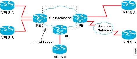
Virtual Private LAN Services (VPLS) uses the provider core to join multiple attachment circuits together to simulate a virtual bridge that connects the multiple attachment circuits together. From a customer point of view, there is no topology for VPLS. All of the CE devices appear to connect to a logical bridge emulated by the provider core (see the figure below).
Full-Mesh Configuration
The full-mesh configuration requires a full mesh of tunnel label switched paths (LSPs) between all the PEs that participate in the VPLS. With full-mesh, signaling overhead and packet replication requirements for each provisioned VC on a PE can be high.
You set up a VPLS by first creating a virtual forwarding instance (VFI) on each participating PE router. The VFI specifies the VPN ID of a VPLS domain, the addresses of other PE routers in the domain, and the type of tunnel signaling and encapsulation mechanism for each peer PE router.
The set of VFIs formed by the interconnection of the emulated VCs is called a VPLS instance; it is the VPLS instance that forms the logic bridge over a packet switched network. The VPLS instance is assigned a unique VPN ID.
The PE routers use the VFI to establish a full-mesh LSP of emulated VCs to all the other PE routers in the VPLS instance. PE routers obtain the membership of a VPLS instance through static configuration using the Cisco IOS CLI.
The full-mesh configuration allows the PE router to maintain a single broadcast domain. Thus, when the PE router receives a broadcast, multicast, or unknown unicast packet on an attachment circuit, it sends the packet out on all other attachment circuits and emulated circuits to all other CE devices participating in that VPLS instance. The CE devices see the VPLS instance as an emulated LAN.
To avoid the problem of a packet looping in the provider core, the PE devices enforce a "split-horizon" principle for the emulated VCs. That means if a packet is received on an emulated VC, it is not forwarded on any other emulated VC.
After the VFI has been defined, it needs to be bound to an attachment circuit to the CE device.
The packet forwarding decision is made by looking up the Layer 2 virtual forwarding instance (VFI) of a particular VPLS domain.
A VPLS instance on a particular PE router receives Ethernet frames that enter on specific physical or logical ports and populates a MAC table similarly to how an Ethernet switch works. The PE router can use the MAC address to switch those frames into the appropriate LSP for delivery to the another PE router at a remote site.
If the MAC address is not in the MAC address table, the PE router replicates the Ethernet frame and floods it to all logical ports associated with that VPLS instance, except the ingress port where it just entered. The PE router updates the MAC table as it receives packets on specific ports and removes addresses not used for specific periods.
Static VPLS Configuration

H-VPLS
Hierarchical VPLS (H-VPLS) reduces both signaling and replication overhead by using both full-mesh as well as hub and spoke configurations. Hub and spoke configurations operate with split horizon to allow packets to be switched between pseudo-wires (PWs), effectively reducing the number of PWs between PEs.
Note | Split horizon is the default configuration to avoid broadcast packet looping. To avoid looping when using the no-split-horizon keyword, be very mindful of your network configuration. |
Supported Features
- Multipoint-to-Multipoint Support
- Non-Transparent Operation
- Circuit Multiplexing
- MAC-Address Learning Forwarding and Aging
- Jumbo Frame Support
- Q-in-Q Support and Q-in-Q to EoMPLS Support
- VPLS Services
Multipoint-to-Multipoint Support
Two or more devices are associated over the core network. No one device is designated as the Root node, but all devices are treated as Root nodes. All frames can be exchanged directly between nodes.
Non-Transparent Operation
A virtual Ethernet connection (VEC) can be transparent or non-transparent with respect to Ethernet PDUs (that is, BPDUs). The purpose of VEC non-transparency is to allow the end user to have a Frame Relay-type service between Layer 3 devices.
Circuit Multiplexing
Circuit Multiplexing allows a node to participate in multiple services over a single Ethernet connection. By participating in multiple services, the Ethernet connection is attached to multiple logical networks. Some examples of possible service offerings are VPN services between sites, Internet services, and third-party connectivity for intercompany communications.
MAC-Address Learning Forwarding and Aging
PEs must learn remote MAC addresses and directly attached MAC addresses on customer facing ports. MAC address learning accomplishes this by deriving topology and forwarding information from packets originating at customer sites. A timer is associated with stored MAC addresses. After the timer expires, the entry is removed from the table.
Jumbo Frame Support
Jumbo frame support provides support for frame sizes between 1548 through 9216 bytes. You use the CLI to establish the jumbo frame size for any value specified in the above range. The default value is 1500 bytes in any Layer 2/VLAN interface. You can configure jumbo frame support on a per-interface basis.
Q-in-Q Support and Q-in-Q to EoMPLS Support
With 802.1Q tunneling (Q-in-Q), the CE issues VLAN-tagged packets and the VPLS forwards the packets to a far-end CE. Q-in-Q refers to the fact that one or more 802.1Q tags may be located in a packet within the interior of the network. As packets are received from a CE device, an additional VLAN tag is added to incoming Ethernet packets to segregate traffic from different CE devices. Untagged packets originating from the CE use a single tag within the interior of the VLAN switched network, while previously tagged packets originating from the CE use two or more tags.
VPLS Services
Transparent LAN Service
Transparent LAN Service (TLS) is an extension to the point-to-point port-based EoMPLS, used to provide bridging protocol transparency (for example, bridge protocol data units [BPDUs]) and VLAN values. Bridges see this service as an Ethernet segment. With TLS, the PE router forwards all Ethernet packets received from the customer-facing interface (including tagged, untagged, and BPDUs) as follows:
- To a local Ethernet interface or an emulated VC if the destination MAC address is found in the Layer 2 forwarding table.
- To all other local Ethernet interfaces and emulated VCs belonging to the same VPLS domain if the destination MAC address is a multicast or broadcast address or if the destination MAC address is not found in the Layer 2 forwarding table.
Note | You must enable Layer 2 protocol tunneling to run the Cisco Discovery Protocol (CDP), the VLAN Trunking Protocol (VTP), and the Spanning-Tree Protocol (STP). |
Ethernet Virtual Connection Service
Ethernet Virtual Connection Service (EVCS) is an extension to the point-to-point VLAN-based EoMPLS that allows routers to reach multiple intranet and extranet locations from a single physical port. Routers see subinterfaces through which they access other routers. With EVCS, the PE router forwards all Ethernet packets with a particular VLAN tag received from the customer-facing interface (excluding BPDUs) as follows:
- To a local Ethernet interface or to an emulated VC if the destination MAC address is found in the Layer 2 forwarding table.
- To all other local Ethernet interfaces and emulated VCs belonging to the same VPLS domain if the destination MAC address is a multicast or broadcast address or if the destination MAC address is not found in the Layer 2 forwarding table.
Note | Because it has only local significance, the demultiplexing VLAN tag that identifies a VPLS domain is removed before forwarding the packet to the outgoing Ethernet interfaces or emulated VCs. |
Prerequisites
Before you configure VPLS, ensure that the network is configured as follows:
- Configure IP routing in the core so that the PE routers can reach each other via IP.
- Configure MPLS in the core so that a label switched path (LSP) exists between the PE routers.
- Configure a loopback interface for originating and terminating Layer 2 traffic. Make sure the PE routers can access the other router's loopback interface. Note that the loopback interface is not needed in all cases. For example, tunnel selection does not need a loopback interface when VPLS is directly mapped to a TE tunnel.
VPLS configuration requires you to identify peer PE routers and to attach Layer 2 circuits to the VPLS at each PE router.
Restrictions for VPLS
The following general restrictions pertain to all transport types under VPLS:
- Split horizon is the default configuration to avoid broadcast packet looping and to isolate Layer 2 traffic. Split horizon prevents packets received from an emulated VC from being forwarded into another emulated VC. This technique is important for creating loop-free paths in a full-meshed network.
-
Supported maximum values:
- Total number of VFIs: 4,096 (4K)
- Maximum combined number of edge and the core peer PEs per VFI:
--VPLS: 250
--H-VPLS 500
-
- Total number of VC: 12,288 (12K)
- No software-based data plane is supported.
- No auto-discovery mechanism is supported.
- Load sharing and failover on redundant CE-PE links are not supported.
- The addition or removal of MAC addresses with Label Distribution Protocol (LDP) is not supported.
- The virtual forwarding instance (VFI) is supported only with the interface vlan command.
Configuring VPLS
- Configuring PE Layer 2 Interfaces to CEs
- Configuring MPLS in the PE
- Configuring the VFI in the PE
- VPLS Integrated Routing and Bridging
Configuring PE Layer 2 Interfaces to CEs
- Configuring 802.1Q Access Ports for Tagged Traffic from a CE
- Configuring Access Ports for Untagged Traffic from CE
- Configuring Q-in-Q EFP
Configuring 802.1Q Access Ports for Tagged Traffic from a CE
DETAILED STEPS
Examples
This example shows how to configure the tagged traffic.
Router(config)# interface GigabitEthernet4/4
Router(config-if)# no ip address
Router(config-if)# negotiation auto
Router(config-if)# service instance 10 ethernet
Router(config-if-srv)# encapsulation dot1q 200
Router(config-if-srv)# bridge-domain 100
This example shows how to use the show run interface command to verify the configuration.
Router# show run interface GigabitEthernet4/4
Building configuration...
Current configuration : 212 bytes
!
interface GigabitEthernet4/4
 no ip address
 negotiation auto
 service instance 10 ethernet
 encapsulation dot1q 200
 bridge-domain 100
end
Configuring Access Ports for Untagged Traffic from CE
DETAILED STEPS
Examples
This example shows how to configure the untagged traffic.
Router(config)# interface GigabitEthernet4/4
Router(config-if)# no ip address
Router(config-if)# negotiation auto
Router(config-if)# service instance 10 ethernet
Router(config-if-srv)# encapsulation untaggged
Router(config-if-srv)# bridge-domain 100
This example shows how to use the show run interface command to verify the configuration.
Router# show run interface GigabitEthernet4/4
Building configuration...
Current configuration : 212 bytes
!
interface GigabitEthernet4/4
 no ip address
 nonegotiation auto
 service instance 10 ethernet
 encapsulation untagged
 bridge-domain 100
end
Configuring Q-in-Q EFP
DETAILED STEPS
Examples
This example shows how to configure the tagged traffic.
Router(config)# interface GigabitEthernet4/4
Router(config-if)# no ip address
Router(config-if)# nonegotiate auto
Router(config-if)# service instance 10 ethernet
Router(config-if-srv)# encapsulation dot1q 200 second-dot1q 400
Router(config-if-srv)# bridge-domain 100
This example shows how to use the show run interface command to verify the configuration.
Router# show run interface GigabitEthernet4/4
Building configuration...
Current configuration : 212 bytes
!
interface GigabitEthernet4/4
 no ip address
 negotiate auto
 service instance 10 ethernet
 encapsulation dot1q 200 second-dot1q 400
 bridge-domain 100
end
Use the show spanning-tree vlan command to verify the port is not in a blocked state.
Use the show vlan id command to verify that a specific port is configured to send and receive a specific VLAN's traffic.
Configuring MPLS in the PE
To configure MPLS in the PE, you must provide the required MPLS parameters.
DETAILED STEPS
Examples
This example shows global MPLS configuration.
Router(config)# mpls label protocol ldp
Router(config)# tag-switching tdp discovery directed hello
Router(config)# tag-switching tdp router-id Loopback0 force
Use the show ip cef command to verify that the LDP label is assigned.
Router# show ip cef 192.168.17.7
192.168.17.7/32, version 272, epoch 0, cached adjacency to POS4/1
0 packets, 0 bytes
  tag information set
    local tag: 8149
    fast tag rewrite with PO4/1, point2point, tags imposed: {4017}
  via 11.3.1.4, POS4/1, 283 dependencies
    next hop 11.3.1.4, POS4/1
    valid cached adjacency
    tag rewrite with PO4/1, point2point, tags imposed: {4017}
Configuring the VFI in the PE
The virtual switch instance (VFI) specifies the VPN ID of a VPLS domain, the addresses of other PE routers in this domain, and the type of tunnel signaling and encapsulation mechanism for each peer. (This is where you create the VSI and associated VCs.) Configure a VFI as follows:
Note | Only MPLS encapsulation is supported. |
DETAILED STEPS
Examples
The following example shows a VFI configuration.
Router(config)# l2 vfi VPLSA manual
Router(config-vfi)# vpn id 110
Router(config-vfi)# neighbor 11.11.11.11 encapsulation mpls
Router(config-vfi)# neighbor 33.33.33.33 encapsulation mpls
Router(config-vfi)# neighbor 44.44.44.44 encapsulation mpls
Router(config-vfi)# bridge-domain 100
The following example shows a VFI configuration for hub and spoke.
Router(config)# l2 vfi VPLSA manual
Router(config-vfi)# vpn id 110
Router(config-vfi)# neighbor 9.9.9.9 encapsulation mpls
Router(config-vfi)# neighbor 12.12.12.12 encapsulation mpls
Router(config-vfi)# neighbor 33.33.33.33 encapsulation mpls no-split-horizon
Router(config-vfi)# bridge-domain 100
The show mpls 12transport vc command displays various information related to PE1.
Note | The show mpls l2transport vc [detail] command is also available to show detailed information about the VCs on a PE router as in the following example. |
VPLS-PE2# show mpls l2transport vc 201
Local intf     Local circuit        Dest address    VC ID      Status
-------------  -------------------- --------------- ---------- ----------
VFI test1      VFI                  153.1.0.1       201        UP
VFI test1      VFI                  153.3.0.1       201        UP
VFI test1      VFI                  153.4.0.1       201        UP
Note | The VC ID in the output represents the VPN ID; the VC is identified by the combination of the Dest address and the VC ID as in the example below. |
The show vfi vfi name command shows VFI status.
nPE-3# show vfi VPLS-2
VFI name: VPLS-2, state: up
  Local attachment circuits:
    Vlan2
  Neighbors connected via pseudowires:
  Peer Address     VC ID     Split-horizon
  1.1.1.1          2             Y
  1.1.1.2          2             Y
  2.2.2.3          2             N
VPLS Integrated Routing and Bridging
VPLS integrated routing and bridging can route Layer 3 traffic as well as switch Layer 2 frames for pseudowire connections between provider edge (PE) devices using Virtual Private LAN Services (VPLS) multipoint PE. The ability to route frames to and from these interfaces supports termination of a pseudowire into a Layer 3 network (VPN or global) on the same switch, or to tunnel Layer 3 frames over a Layer 2 tunnel (VPLS).
Note | VPLS integrated routing and bridging is also known as routed pseudowire and routed VPLS. |
To configure routing support for the pseudowire, configure an IP address and other Layer 3 features for the Layer 3 domain (VPN or global) in the interface configuration.
interface bdi 100
  ip address 10.10.10.1 255.255.255.0
interface bdi 200
  ip address 20.20.20.1 255.255.255.0
Configuring Static Virtual Private LAN Services
- Configuring the Pseudowire Class for Static VPLS
- Configuring the VFI for Static VPLS
- Configuring the Attachment Circuit for Status VPLS
- Configuring the MPLS-TP Tunnel for Static VPLS with TP
Configuring the Pseudowire Class for Static VPLS
The successful transmission of the Layer 2 frames between PE routers is due to the configuration of the PE routers. You set up the connection, called a pseudowire, between the routers.
The pseudowire-class configuration is used to configure the VC type for the VPI pseudowire and can specify the pseudowire to use the TP tunnnel.
In the following example, any pseudowire using this pseudowire class will go through a MPLS-TP tunnel (TP-Tunnel 1)
The pseudowire-class configuration group specifies the characteristics of the tunneling mechanism, which are:
Perform this task to configure a pseudowire class for static VLPS.
DETAILED STEPS
| Command or Action | Purpose | |
|---|---|---|
Step 1 |
enable
Example: Router> enable |
Enables privileged EXEC mode. |
Step 2 |
configure
terminal
Example: Router# configure terminal |
Enters global configuration mode. |
Step 3 |
pseudowire-class
pw-name
Example: Router(config)# pseudowire-class static-vlps |
Establishes a pseudowire class with a name that you specify. Enters pseudowire class configuration mode. |
Step 4 |
encapsulation
mpls
Example: Router(config-pw-class)# encapsulation mpls |
Specifies the tunneling encapsulation. For AToM, the encapsulation type is mpls. |
Step 5 |
protocol
none
Example: Router(config-pw-class)# protocol none |
Specifies that no protocol is configured for pseudowire class |
Step 6 |
preferred-path
interface
Tunnel-tp
Example: Router(config-pw-class)# preferred-path interface Tunnel-tpl |
(Optional) Configures the preferred path. |
Step 7 | end
Example: Router(config-pw-class)# end |
Returns to global configuration mode. |
Configuring the VFI for Static VPLS
DETAILED STEPS
| Command or Action | Purpose | |
|---|---|---|
Step 1 |
enable
Example: Router> enable |
Enables privileged EXEC mode. |
Step 2 |
configure
terminal
Example: Router# configure terminal |
Enters global configuration mode. |
Step 3 |
l2
vfi
vfi-name
manual
Example: Router(config)# l2 vfi static-vfi manual |
Creates a Layer 2 VFI and enters Layer 2 VFI manual configuration mode. |
Step 4 |
vpn
id
vpn-id
Example: Router(config-vfi)# vpn id 100 |
Specifies the VPN ID. |
Step 5 |
bridge-domain
bd-id
Example: Router(config-vfi)# bridge-domain 24 |
Specifies the bridge domain ID. |
Step 6 |
neighbor
ip-address
pw-class
pw-name
Example: Router(config-vfi)# neighbor 2.3.4.4 pw-class static-vpls |
Specifies the IP address of the peer and the pseudowire class. |
Step 7 |
mpls
label
local-pseudowire-label
remote-pseudowire-label
Example: Router(config-vfi-neighbor)# mpls label 301 17 |
Configures an Any Transport over MPLS (AToM) static pseudowire connection by defining local and remote circuit labels . |
Step 8 |
[no]
mpls
control-word
Example: Router(config-vfi-neighbor)# mpls control-word | (Optional) Enables the Multiprotocol Label Switching (MPLS) control word in an Any Transport over MPLS (AToM) static pseudowire connection . |
Step 9 |
exit
Example: Router(config-vfi-neighbor)# exit |
Exits the current configuration mode and returns to VFI manual configuration mode. |
Step 10 |
neighbor
ip-address
pw-class
pw-name
Example: Router(config-vfi)# neighbor 2.3.4.3 pw-class static-vpls |
Specifies the IP address of the peer and the pseudowire class. |
Step 11 |
mpls
label
local-pseudowire-label
remote-pseudowire-label
Example: Router(config-vfi-neighbor)# mpls label 302 18 |
Configures an Any Transport over MPLS (AToM) static pseudowire connection by defining local and remote circuit labels . |
Step 12 |
mpls
control-word
Example: Router(config-vfi-neighbor)# mpls control-word | Enables the Multiprotocol Label Switching (MPLS) control word in an Any Transport over MPLS (AToM) static pseudowire connection . |
Step 13 |
end
Example: Router(config-vfi-neighbor)# end |
Exits the current configuration mode and returns to privileged EXEC mode. |
Configuring the Attachment Circuit for Status VPLS
DETAILED STEPS
| Command or Action | Purpose | |
|---|---|---|
Step 1 |
enable
Example: Router> enable |
Enables privileged EXEC mode. |
Step 2 |
configure
terminal
Example: Router# configure terminal |
Enters global configuration mode. |
Step 3 |
interface
gigabitethernet
slot/interface
Example: Router(config)# interface gigabitethernet 1/0 |
Specifies the Gigabit Ethernet subinterface and enters subinterface configuration mode. Make sure the subinterfaces between the CE and PE routers that are running Ethernet over MPLS are in the same subnet. All other subinterfaces and backbone routers do not need to be in the same subnet. |
Step 4 |
service
instance
si-id
ethernet
Example: Router(config-if)# service instance 10 ethernet |
Specifies the service instance ID. |
Step 5 |
encapsulation
dot1q
vlan-id
Example: Router(config-vfi)# encapsulation dot1q 200 |
Enables the subinterface to accept 802.1Q VLAN packets. Make sure the subinterface on the adjoining CE router is on the same VLAN as this PE router. |
Step 6 |
rewrite
ingress
pop
number
symmetric
Example: Router(config-if)# rewrite ingress pop 1 symmetric |
(Optional) Specifies the ingress rewrite |
Step 7 |
bridge-domain
bd-id
Example: Router(config-vfi)# bridge-domain 24 |
( Optional) When the MVR source bridge domain and MVR receiver ports are in a different bridge domain, specifies the bridge domain for which the MVR configuration will be done. |
Step 8 |
end
Example: Router(config-if)# end |
Exits the current configuration mode and returns to privileged EXEC mode. |
Configuring the MPLS-TP Tunnel for Static VPLS with TP
DETAILED STEPS
| Command or Action | Purpose | |
|---|---|---|
Step 1 |
enable
Example: Router> enable |
Enables privileged EXEC mode. |
Step 2 |
configure
terminal
Example: Router# configure terminal |
Enters global configuration mode. |
Step 3 |
Configures a MPLS Transport Profile interface. Enters interface configuration mode. | |
Step 4 | no
ip
address
Example: Router(config-if)# no ip address |
Disables the IP address configuration. |
Step 5 | no
keepalive
Example: Router(config-if)# no keepalive |
Disables the keepalive configuration. |
Step 6 | tp
destination
ip-address
Example: Router(config-if)# tp destination 22.22.22.22 |
Configures the tunnel destination. |
Step 7 | bfd
tp
Example: Router(config-if)# bfd tp |
Configures the Bidirectional Forwarding Detection (BFD) protocol. |
Step 8 | working-lsp
Example: Router(config-if)# working-lsp |
Configures the working label switched path (LSP). |
Step 9 | out-label
number
out-link
number
Example: Router(config-if-working)# out-link 10 out-label 100 |
Configures the out link and out label for the working LSP. |
Step 10 |
in-label
number
Example: Router(config-if-working)# in-label 400 |
Configures the in label for the working LSP. |
Step 11 |
lsp-number
number
Example: Router(config-if-working)# lsp 0 |
Configures the ID number for the working LSP. |
Step 12 | exit
Example: Router(config-if-working)# exit |
Returns to interface configuration mode. |
Step 13 |
protect-lsp
Example: Router(config-if)# protect-lsp |
Enters protection configuration mode for the label switched path (LSP). |
Step 14 | out-label
number
out-link
number
Example: Router(config-if-protect)# out-link 11 out-label 500 |
Configures the out link and out label for the protect LSP. |
Step 15 |
in-label
number
Example: Router(config-if-protect)# in-label 600 |
Configures the in label for the protect LSP. |
Step 16 |
lsp-number
number
Example: Router(config-if-protect)# lsp-number 0 |
Configures the ID number for the working protect LSP. |
Step 17 | exit
Example: Router(config-if-working)# exit |
Returns to interface configuration mode. |
Step 18 |
interface
interface-name
Example: Router(config-if)# interface Ethernet1/0 |
Configures a interface and enters interface configuration mode. |
Step 19 | ip
address
ip_address
ip-mask
Example: Router(config-if)# ip address 20.0.0.1 255.255.255.0 |
(Optional) Configures the IP address and mask if not using IP-less core. |
Step 20 | mpls
tp
link
number {ipv4
ip_address |
tx-mac
mac_address}
Example: Router(config-if)# mpls tp link 10 ipv4 20.0.0.2 |
Configures the MPLS Transport Profile link number and ARP translation. |
Step 21 | end
Example: Router(config-if)# end |
Returns to global configuration mode. |
Full-Mesh Configuration Example
In a full-mesh configuration, each PE router creates a multipoint-to-multipoint forwarding relationship with all other PE routers in the VPLS domain using a VFI. An Ethernet or VLAN packet received from the customer network can be forwarded to one or more local interfaces and or emulated VCs in the VPLS domain. To avoid broadcasted packets looping around in the network, no packet received from an emulated VC can be forwarded to any emulated VC of the VPLS domain on a PE router. That is, the Layer 2 split horizon should always be enabled as the default in a full-mesh network.
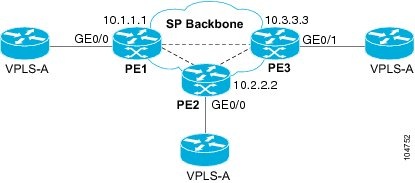
Configuration on PE 1
This shows the creation of the virtual switch instances (VSIs) and associated VCs.
l2 vfi PE1-VPLS-A manual
  vpn id 110
  neighbor 2.2.2.2 encapsulation mpls
  neighbor 3.3.3.3 encapsulation mpls
  bridge domain 100
!
interface Loopback 0
  ip address 1.1.1.1 255.255.255.255
This configures the CE device interface (there can be multiple Layer 2 interfaces in a VLAN).
interface FastEthernet0/0
   no ip address
   negotiation auto
   service instance 10 ethernet
   encapsulation dot1q 200
   bridge-domain 100
Configuration on PE 2
This shows the creation of the virtual switch instances (VSIs) and associated VCs.
l2 vfi PE2-VPLS-A manual
  vpn id 111
  neighbor 1.1.1.1 encapsulation mpls
  neighbor 3.3.3.3 encapsulation mpls
  bridge domain 100
!
interface Loopback 0
  ip address 2.2.2.2 255.255.255.255
This configures the CE device interface (there can be multiple Layer 2 interfaces in a VLAN).
interface FastEthernet0/0
  no ip address
   negotiation auto
   service instance 10 ethernet
   encapsulation dot1q 200
   bridge-domain 100
Configuration on PE 3
This shows the creation of the virtual switch instances (VSIs) and associated VCs.
l2 vfi PE3-VPLS-A manual
  vpn id 112
  neighbor 1.1.1.1 encapsulation mpls
  neighbor 2.2.2.2 encapsulation mpls
  bridge domain 100
!
interface Loopback 0
  ip address 3.3.3.3 255.255.255.255
This configures the CE device interface (there can be multiple Layer 2 interfaces in a VLAN).
interface FastEthernet0/1
   no ip address
   negotiation auto
   service instance 10 ethernet
   encapsulation dot1q 200
   bridge-domain 100
!
The show mpls l2 vc command provides information on the status of the VC.
VPLS1# show mpls l2 vc
Local intf     Local circuit        Dest address    VC ID      Status
-------------  -------------------- --------------- ---------- ----------
Vi1            VFI                  22.22.22.22     200        DOWN
Vi1            VFI                  22.22.22.22     400        UP
Vi1            VFI                  33.33.33.33     200        UP
Vi1            VFI                  44.44.44.44     200        UP
Vi1            VFI                  44.44.44.44     400        UP
The show vfi command provides information on the VFI.
PE-1# show vfi PE1-VPLS-A
VFI name: VPLSA, state: up
  Local attachment circuits:
    Vlan200
  Neighbors connected via pseudowires:
    2.2.2.2  3.3.3.3
The show mpls 12transport vc command provides information the virtual circuits.
Router# show mpls l2 vc det
Local interface: VFI vfi17 up
  Destination address: 1.3.1.1, VC ID: 17, VC status: up
    Tunnel label: imp-null, next hop point2point
    Output interface: PO3/4, imposed label stack {18}
  Create time: 3d15h, last status change time: 1d03h
  Signaling protocol: LDP, peer 1.3.1.1:0 up
    MPLS VC labels: local 18, remote 18
    Group ID: local 0, remote 0
    MTU: local 1500, remote 1500
    Remote interface description:
  Sequencing: receive disabled, send disabled
  VC statistics:
    packet totals: receive 0, send 0
    byte totals:   receive 0, send 0
    packet drops:  receive 0, send 0
Feature Information for Configuring Virtual Private LAN Services
The following table provides release information about the feature or features described in this module. This table lists only the software release that introduced support for a given feature in a given software release train. Unless noted otherwise, subsequent releases of that software release train also support that feature.
Use Cisco Feature Navigator to find information about platform support and Cisco software image support. To access Cisco Feature Navigator, go to www.cisco.com/go/cfn. An account on Cisco.com is not required.
| Table 1 | Feature Information for Configuring Virtual Private LAN Services |
| Feature Name | Releases | Feature Information |
|---|---|---|
|
Virtual Private LAN Services (VPLS) |
Cisco IOS XE Release 3.5S 15.2(1)S |
This feature enables you to configure dynamic Virtual Private LAN Services (VPLS). VPLS is a class of VPN that supports the connection of multiple sites in a single bridged domain over a managed IP/MPLS network. In Cisco IOS XE Release 3.5S, this feature was introduced on the Cisco ASR 1000 Series Aggregation Services Routers. In Cisco IOS XE Release 3.5S, support was added for the Cisco ASR 903 Router. In Cisco IOS Release 15.2(1)S, this feature was integrated. |
|
Static VPLS over MPLS-TP |
Cisco IOS XE Release 3.6S |
This features enables you to static Virtual Private LAN Services to use MPLS Transport Profile (MPLS-TP). In Cisco IOS XE Release 3.5S, this feature was introduced on the Cisco ASR 903 Router. |
Cisco and the Cisco logo are trademarks or registered trademarks of Cisco and/or its affiliates in the U.S. and other countries. To view a list of Cisco trademarks, go to this URL: www.cisco.com/go/trademarks. Third-party trademarks mentioned are the property of their respective owners. The use of the word partner does not imply a partnership relationship between Cisco and any other company. (1110R)
Any Internet Protocol (IP) addresses and phone numbers used in this document are not intended to be actual addresses and phone numbers. Any examples, command display output, network topology diagrams, and other figures included in the document are shown for illustrative purposes only. Any use of actual IP addresses or phone numbers in illustrative content is unintentional and coincidental.