
 Feedback
Contents
- L2VPN Pseudowire Redundancy
- Finding Feature Information
- Prerequisites for L2VPN Pseudowire Redundancy
- Restrictions for L2VPN Pseudowire Redundancy
- Information About L2VPN Pseudowire Redundancy
- Introduction to L2VPN Pseudowire Redundancy
- How to Configure L2VPN Pseudowire Redundancy
- Configuring the Pseudowire
- Configuring L2VPN Pseudowire Redundancy
- Forcing a Manual Switchover to the Backup Pseudowire VC
- Verifying the L2VPN Pseudowire Redundancy Configuration
- Configuration Examples for L2VPN Pseudowire Redundancy
- L2VPN Pseudowire Redundancy and AToM Like to Like Examples
- L2VPN Pseudowire Redundancy and L2VPN Interworking Examples
- L2VPN Pseudowire Redundancy with Layer 2 Local Switching Examples
- Additional References
- Feature Information for L2VPN Pseudowire Redundancy
L2VPN Pseudowire Redundancy
The L2VPN Pseudowire Redundancy feature lets you configure your network to detect a failure in the network and reroute the Layer 2 (L2) service to another endpoint that can continue to provide service. This feature provides the ability to recover from a failure either of the remote provider edge (PE) router or of the link between the PE and customer edge (CE) routers.
- Finding Feature Information
- Prerequisites for L2VPN Pseudowire Redundancy
- Restrictions for L2VPN Pseudowire Redundancy
- Information About L2VPN Pseudowire Redundancy
- How to Configure L2VPN Pseudowire Redundancy
- Configuration Examples for L2VPN Pseudowire Redundancy
- Additional References
- Feature Information for L2VPN Pseudowire Redundancy
Finding Feature Information
Your software release may not support all the features documented in this module. For the latest feature information and caveats, see the release notes for your platform and software release. To find information about the features documented in this module, and to see a list of the releases in which each feature is supported, see the Feature Information Table at the end of this document.
Use Cisco Feature Navigator to find information about platform support and Cisco software image support. To access Cisco Feature Navigator, go to www.cisco.com/go/cfn. An account on Cisco.com is not required.
Prerequisites for L2VPN Pseudowire Redundancy
-
This feature module requires that you understand how to configure basic L2 virtual private networks (VPNs). You can find that information in the following documents:
- Any Transport over MPLS
- L2 VPN Interworking
-
The L2VPN Pseudowire Redundancy feature requires that the following mechanisms be in place to enable you to detect a failure in the network:
- Label-switched paths (LSP) Ping/Traceroute and Any Transport over MPLS Virtual Circuit Connection Verification (AToM VCCV)
- Local Management Interface (LMI)
- Operation, Administration, and Maintenance (OAM)
Restrictions for L2VPN Pseudowire Redundancy
General Restrictions
- The primary and backup pseudowires must run the same type of transport service. The primary and backup pseudowires must be configured with AToM.
- Only static, on-box provisioning is supported.
- If you use L2VPN Pseudowire Redundancy with L2VPN Interworking, the interworking method must be the same for the primary and backup pseudowires.
- Setting the experimental (EXP) bit on the Multiprotocol Label Switching (MPLS) pseudowire is supported.
- Different pseudowire encapsulation types on the MPLS pseudowire are not supported.
- The mpls l2transport route command is not supported. Use the xconnect command instead.
- The ability to have the backup pseudowire fully operational at the same time that the primary pseudowire is operational is not supported. The backup pseudowire becomes active only after the primary pseudowire fails.
- The AToM VCCV feature is supported only on the active pseudowire.
- More than one backup pseudowire is not supported.
Restrictions for Layer 2 Tunnel Protocol Version 3 (L2TPv3) Xconnect Configurations
- Interworking is not supported.
- Local switching backup by pseudowire redundancy is not supported.
- PPP, HDLC, and Frame-Relay attachment circuit (AC) types of L2TPv3 pseudowire redundancy are not supported.
- For the edge interface, only the Cisco 7600 series SPA Interface Processor-400 (SIP-400) linecard with the following shared port adapters (SPAs) is supported:
Cisco 2-Port Gigabit Ethernet Shared Port Adapter (SPA-2X1GE) Cisco 2-Port Gigabit Ethernet Shared Port Adapter, Version 2 (SPA-2X1GE-V2) Cisco 5-Port Gigabit Ethernet Shared Port Adapter, Version 2 (SPA-5X1GE-V2) Cisco 10-Port Gigabit Ethernet Shared Port Adapter, Version 2 (SPA-10X1GE-V2) Cisco 2-Port OC3c/STM1c ATM Shared Port Adapter (SPA-2XOC3-ATM) Cisco 4-Port OC3c/STM1c ATM Shared Port Adapter (SPA-4XOC3-ATM) Cisco 1-Port OC12c/STM4c ATM Shared Port Adapter (SPA-1XOC12-ATM) Cisco 1-Port OC-48c/STM-16 ATM Shared Port Adapter (SPA-1XOC48-ATM)
Information About L2VPN Pseudowire Redundancy
Introduction to L2VPN Pseudowire Redundancy
L2VPNs can provide pseudowire resiliency through their routing protocols. When connectivity between end-to-end PE routers fails, an alternative path to the directed LDP session and the user data can take over. However, there are some parts of the network where this rerouting mechanism does not protect against interruptions in service. The figure below shows those parts of the network that are vulnerable to an interruption in service.
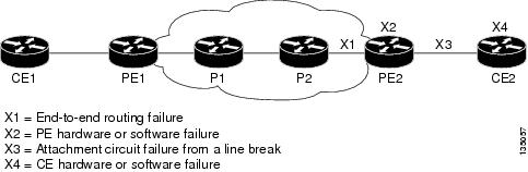
The L2VPN Pseudowire Redundancy feature provides the ability to ensure that the CE2 router in the figure above can always maintain network connectivity, even if one or all the failures in the figure occur.
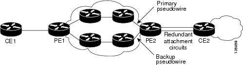
The L2VPN Pseudowire Redundancy feature enables you to set up backup pseudowires. You can configure the network with redundant pseudowires (PWs) and redundant network elements, which are shown in the three figures below.
The figure below shows a network with redundant pseudowires and redundant attachment circuits.
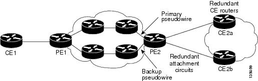
The figure below shows a network with redundant pseudowires, attachment circuits, and CE routers.
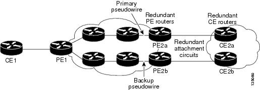
The figure below shows a network with redundant pseudowires, attachment circuits, CE routers, and PE routers.
How to Configure L2VPN Pseudowire Redundancy
The L2VPN Pseudowire Redundancy feature enables you to configure a backup pseudowire in case the primary pseudowire fails. When the primary pseudowire fails, the PE router can switch to the backup pseudowire. You can have the primary pseudowire resume operation after it comes back up.
The default Label Distribution Protocol (LDP) session hold-down timer will enable the software to detect failures in about 180 seconds. That time can be configured so that the software can detect failures more quickly. See the mpls ldp holdtime command for more information.
- Configuring the Pseudowire
- Configuring L2VPN Pseudowire Redundancy
- Forcing a Manual Switchover to the Backup Pseudowire VC
- Verifying the L2VPN Pseudowire Redundancy Configuration
Configuring the Pseudowire
The successful transmission of the Layer 2 frames between PE routers is due to the configuration of the PE routers. You set up the connection, called a pseudowire, between the routers.
The pseudowire-class configuration group specifies the characteristics of the tunneling mechanism, which are:
- Encapsulation type
- Control protocol
- Payload-specific options
You must specify the encapsulation mplscommand as part of the pseudowire class for the AToM VCs to work properly. If you omit the encapsulation mplscommand as part of the xconnectcommand, you receive the following error:
% Incomplete command.
Perform this task to configure a pseudowire class.
DETAILED STEPS
Configuring L2VPN Pseudowire Redundancy
For each transport type, the xconnectcommand is configured slightly differently. The following configuration steps use Ethernet VLAN over MPLS, which is configured in subinterface configuration mode. See Any Transport over MPLS to determine how to configure the xconnect command for other transport types.
DETAILED STEPS
Forcing a Manual Switchover to the Backup Pseudowire VC
To force the router switch over to the backup or primary pseudowire, you can enter the xconnect backup force switchover command in privileged EXEC mode. You can specify either the interface of the primary attachment circuit (AC) to switch to or the IP-address and VC ID of the peer router.
A manual switchover can be made only if the interface or peer specified in the command is actually available and the xconnect will move to the fully active state when the command is entered.
DETAILED STEPS
Verifying the L2VPN Pseudowire Redundancy Configuration
Use the following commands to verify that the L2VPN Pseudowire Redundancy feature is correctly configured.
DETAILED STEPS
| Step 1 |
show
mpls
l2transport
vc
In this example, the primary attachment circuit is up. The backup attachment circuit is available, but not currently selected. The show output displays as follows: Example: Router# show mpls l2transport vc Local intf Local circuit Dest address VC ID Status ------------- ----------------------- --------------- ---------- ---------- Et0/0.1 Eth VLAN 101 10.0.0.2 101 UP Et0/0.1 Eth VLAN 101 10.0.0.3 201 DOWN Router# show mpls l2transport vc detail Local interface: Et0/0.1 up, line protocol up, Eth VLAN 101 up Destination address 10.0.0.2 VC ID: 101, VC status UP . . . Local interface: Et0/0.1 down, line protocol down, Eth VLAN 101 down Destination address 10.0.0.3 VC ID: 201, VC status down . . . |
| Step 2 |
show
xconnect
all
In this example, the topology is Attachment Circuit 1 to Pseudowire 1 with a Pseudowire 2 as a backup: Example:
Router# show xconnect all
Legend: XC ST=Xconnect State, S1=Segment1 State, S2=Segment2 State
UP=Up, DN=Down, AD=Admin Down, IA=Inactive, NH=No Hardware
XC ST  Segment 1                         S1 Segment 2                         S2
------+---------------------------------+--+---------------------------------+--
UP pri ac   Et0/0(Ethernet)              UP mpls 10.55.55.2:1000              UP
IA sec ac   Et0/0(Ethernet)              UP mpls 10.55.55.3:1001              DN
In this example, the topology is Attachment Circuit 1 to Attachment Circuit 2 with a Pseudowire backup for Attachment Circuit 2: Example:
Router# show xconnect all
Legend: XC ST=Xconnect State, S1=Segment1 State, S2=Segment2 State
UP=Up, DN=Down, AD=Admin Down, IA=Inactive, NH=No Hardware
XC ST  Segment 1                         S1 Segment 2                         S2
------+---------------------------------+--+---------------------------------+--
UP pri ac   Se6/0:150(FR DLCI)           UP ac   Se8/0:150(FR DLCI)           UP
IA sec ac   Se6/0:150(FR DLCI)           UP mpls 10.55.55.3:7151              DN
|
| Step 3 |
xconnect
logging
redundancy
In addition to the show mpls l2transport vccommand and the show xconnect command, you can use the xconnect logging redundancy command to track the status of the xconnect redundancy group: Example:
Router(config)# xconnect logging redundancy
When this command is configured, the following messages will be generated during switchover events: Activating the primary member: Example: 00:01:07: %XCONNECT-5-REDUNDANCY: Activating primary member 10.55.55.2:1000 Activating the backup member: Example: 00:01:05: %XCONNECT-5-REDUNDANCY: Activating secondary member 10.55.55.3:1001 |
Configuration Examples for L2VPN Pseudowire Redundancy
Each of the configuration examples refers to one of the following pseudowire classes:
- AToM (like-to-like) pseudowire class:
pseudowire-class mpls
 encapsulation mpls
- L2VPN IP interworking:
pseudowire-class mpls-ip
 encapsulation mpls
 interworking ip
- L2VPN Pseudowire Redundancy and AToM Like to Like Examples
- L2VPN Pseudowire Redundancy and L2VPN Interworking Examples
- L2VPN Pseudowire Redundancy with Layer 2 Local Switching Examples
L2VPN Pseudowire Redundancy and AToM Like to Like Examples
The following example shows a High-Level Data Link Control (HDLC) attachment circuit xconnect with a backup pseudowire:
interface Serial4/0
 xconnect 10.55.55.2 4000 pw-class mpls
 backup peer 10.55.55.3 4001 pw-class mpls
The following example shows a Frame Relay attachment circuit xconnect with a backup pseudowire:
connect fr-fr-pw Serial6/0 225 l2transport
 xconnect 10.55.55.2 5225 pw-class mpls
 backup peer 10.55.55.3 5226 pw-class mpls
L2VPN Pseudowire Redundancy and L2VPN Interworking Examples
The following example shows an Ethernet attachment circuit xconnect with L2VPN IP interworking and a backup pseudowire:
interface Ethernet0/0
 xconnect 10.55.55.2 1000 pw-class mpls-ip
 backup peer 10.55.55.3 1001 pw-class mpls-ip
The following example shows an Ethernet VLAN attachment circuit xconnect with L2VPN IP interworking and a backup pseudowire:
interface Ethernet1/0.1
 encapsulation dot1Q 200
 no ip directed-broadcast
 xconnect 10.55.55.2 5200 pw-class mpls-ip
 backup peer 10.55.55.3 5201 pw-class mpls-ip
The following example shows a Frame Relay attachment circuit xconnect with L2VPN IP interworking and a backup pseudowire:
connect fr-ppp-pw Serial6/0 250 l2transport
 xconnect 10.55.55.2 8250 pw-class mpls-ip
 backup peer 10.55.55.3 8251 pw-class mpls-ip
The following example shows a PPP attachment circuit xconnect with L2VPN IP interworking and a backup pseudowire:
interface Serial7/0
 encapsulation ppp
 xconnect 10.55.55.2 2175 pw-class mpls-ip
 backup peer 10.55.55.3 2176 pw-class mpls-ip
L2VPN Pseudowire Redundancy with Layer 2 Local Switching Examples
The following example shows an Ethernet VLAN-VLAN local switching xconnect with a pseudowire backup for Ethernet segment E2/0.2. If the subinterface associated with E2/0.2 goes down, the backup pseudowire is activated.
connect vlan-vlan Ethernet1/0.2 Ethernet2/0.2
 backup peer 10.55.55.3 1101 pw-class mpls
The following example shows a Frame Relay-to-Frame Relay local switching connect with a pseudowire backup for Frame Relay segment S8/0 150. If data-link connection identifier (DLCI) 150 on S8/0 goes down, the backup pseudowire is activated.
connect fr-fr-ls Serial6/0 150 Serial8/0 150
 backup peer 10.55.55.3 7151 pw-class mpls
Additional References
Related Documents
|
Related Topic |
Document Title |
|---|---|
|
Any Transport over MPLS |
Any Transport over MPLS |
|
High Availability for AToM |
AToM Graceful Restart |
|
L2VPN Interworking |
L2VPN Interworking |
|
Layer 2 local switching |
Layer 2 Local Switching |
|
PWE3 MIB |
Pseudowire Emulation Edge-to-Edge MIBs for Ethernet and Frame Relay Services |
|
Packet sequencing |
Any Transport over MPLS (AToM) Sequencing Support |
MIBs
Technical Assistance
|
Description |
Link |
|---|---|
|
The Cisco Support website provides extensive online resources, including documentation and tools for troubleshooting and resolving technical issues with Cisco products and technologies. To receive security and technical information about your products, you can subscribe to various services, such as the Product Alert Tool (accessed from Field Notices), the Cisco Technical Services Newsletter, and Really Simple Syndication (RSS) Feeds. Access to most tools on the Cisco Support website requires a Cisco.com user ID and password. |
Feature Information for L2VPN Pseudowire Redundancy
The following table provides release information about the feature or features described in this module. This table lists only the software release that introduced support for a given feature in a given software release train. Unless noted otherwise, subsequent releases of that software release train also support that feature.
Use Cisco Feature Navigator to find information about platform support and Cisco software image support. To access Cisco Feature Navigator, go to www.cisco.com/go/cfn. An account on Cisco.com is not required.
| Table 1 | Feature Information for L2VPN Pseudowire Redundancy |
|
Feature Name |
Releases |
Feature Information |
|---|---|---|
|
L2VPN Pseudowire Redundancy |
12.0(31)S 12.2(28)SB 12.2(22)SXI 12.2(33)SRB 12.4(11)T 15.0(1)S |
This feature enables you to set up your network to detect a failure in the network and reroute the Layer 2 service to another endpoint that can continue to provide service. In Cisco IOS Release 12.0(31)S, the L2VPN Pseudowire Redundancy feature was introduced for Any Transport over MPLS (AToM) on the Cisco 12000 series routers. This feature was integrated into Cisco IOS Release 12.2(28)SB. This feature was integrated into Cisco IOS Release 12.4(11)T. This feature was integrated into Cisco IOS Release 12.2(33)SRB. This feature was integrated into Cisco IOS Release 12.2(33)SXI. The following commands were introduced or modified: backup delay (L2VPN local switching), backup peer, show xconnect, xconnect backup force-switchover, xconnect logging redundancy. |
|
L2VPN Pseudowire Redundancy for L2TPv3 |
12.2(33)SRE 15.0(1)S |
This feature provides L2VPN pseudowire redundancy for L2TPv3 xconnect configurations. In Cisco IOS Release 12.2(33)SRE, this feature was implemented on the Cisco 7600 series routers. |
|
Resilient Pseudowire (RPW): PW Fast Recovery |
15.2(1)S |
This feature was integrated into Cisco IOS Release 15.2(1)S. The following commands were introduced or modified: aps hspw-icrm-grp , show hspw-aps-icrm. |
Cisco and the Cisco logo are trademarks or registered trademarks of Cisco and/or its affiliates in the U.S. and other countries. To view a list of Cisco trademarks, go to this URL: www.cisco.com/go/trademarks. Third-party trademarks mentioned are the property of their respective owners. The use of the word partner does not imply a partnership relationship between Cisco and any other company. (1110R)
Any Internet Protocol (IP) addresses and phone numbers used in this document are not intended to be actual addresses and phone numbers. Any examples, command display output, network topology diagrams, and other figures included in the document are shown for illustrative purposes only. Any use of actual IP addresses or phone numbers in illustrative content is unintentional and coincidental.