
 Feedback
Contents
- L2VPN Pseudowire Switching
- Finding Feature Information
- Prerequisites for L2VPN Pseudowire Switching
- Restrictions for L2VPN Pseudowire Switching
- Information About L2VPN Pseudowire Switching
- How L2VPN Pseudowire Switching Works
- How Packets Are Manipulated at the L2VPN Pseudowire Switching Aggregation Point
- How to Configure L2VPN Pseudowire Switching
- Examples
- Configuration Examples for L2VPN Pseudowire Switching
- L2VPN Pseudowire Switching in an Inter-AS Configuration Example
- Additional References
- Feature Information for L2VPN Pseudowire Switching
L2VPN Pseudowire Switching
This feature module explains how to configure L2VPN Pseudowire Switching, which extends Layer 2 Virtual Private Network (L2VPN) pseudowires across an interautonomous system (inter-AS) boundary or across two separate Multiprotocol Label Switching (MPLS) networks. The feature supports ATM and time-division multiplexing (TDM) attachment circuits (ACs) and Ethernet ACs.
- Finding Feature Information
- Prerequisites for L2VPN Pseudowire Switching
- Restrictions for L2VPN Pseudowire Switching
- Information About L2VPN Pseudowire Switching
- How to Configure L2VPN Pseudowire Switching
- Configuration Examples for L2VPN Pseudowire Switching
- Additional References
- Feature Information for L2VPN Pseudowire Switching
Finding Feature Information
Your software release may not support all the features documented in this module. For the latest feature information and caveats, see the release notes for your platform and software release. To find information about the features documented in this module, and to see a list of the releases in which each feature is supported, see the Feature Information Table at the end of this document.
Use Cisco Feature Navigator to find information about platform support and Cisco software image support. To access Cisco Feature Navigator, go to www.cisco.com/go/cfn. An account on Cisco.com is not required.
Prerequisites for L2VPN Pseudowire Switching
For the Cisco 12000 series routers, the L2VPN Pseudowire Switching feature for Any Transport over MPLS (AToM) is supported on the following engines:
- E2
- E3
- E4+
- E5
- E6
For engines that do not support this feature, the packets are sent to the software and forwarded through the slow path.
 Note | Engines E1 and E4 do not support L2VPN Pseudowire Switching, even in the slow path. |
Restrictions for L2VPN Pseudowire Switching
- L2VPN Pseudowire Switching is supported with AToM.
- Only static, on-box provisioning is supported.
- Sequencing numbers in AToM packets are not processed by L2VPN Pseudowire Switching. The feature blindly passes the sequencing data through the xconnect packet paths, a process that is called transparent sequencing. The endpoint provider-edge (PE) to customer-edge (CE) connections enforce the sequencing.
- You can ping the adjacent next-hop PE router. End-to-end label switched path (LSP) pings are not supported.
- Do not configure IP or Ethernet interworking on a router where L2VPN Pseudowire Switching is enabled. Instead, configure interworking on the routers at the edge PEs of the network.
- The control word negotiation results must match. If either segment does not negotiate the control word, the control word is disabled for both segments.
- AToM Graceful Restart is negotiated independently on each pseudowire segment. If there is a transient loss of the label distribution protocol (LDP) session between two AToM PE routers, packets continue to flow.
- Per-pseudowire quality of service (QoS) is not supported. Traffic engineering (TE) tunnel selection is supported.
- Attachment circuit interworking is not supported.
Information About L2VPN Pseudowire Switching
- How L2VPN Pseudowire Switching Works
- How Packets Are Manipulated at the L2VPN Pseudowire Switching Aggregation Point
How L2VPN Pseudowire Switching Works
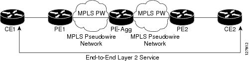
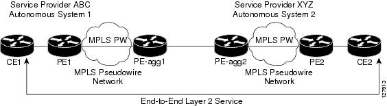
L2VPN Pseudowire Switching allows the user to extend L2VPN pseudowires across two separate MPLS networks or across an inter-AS boundary, as shown in the two figures below.
L2VPN Pseudowire Switching connects two or more contiguous pseudowire segments to form an end-to-end multihop pseudowire. This end-to-end pseudowire functions as a single point-to-point pseudowire.
As shown in the second figure below, L2VPN Pseudowire Switching enables you to keep the IP addresses of the edge PE routers private across inter-AS boundaries. You can use the IP address of the Autonomous System Boundary Routers (ASBRs) and treat them as pseudowire aggregation (PE-agg) routers. The ASBRs join the pseudowires of the two domains.
L2VPN Pseudowire Switching also enables you to keep different administrative or provisioning domains to manage the end-to-end service. At the boundaries of these networks, PE-agg routers delineate the management responsibilities.
How Packets Are Manipulated at the L2VPN Pseudowire Switching Aggregation Point
Switching AToM packets between two AToM pseudowires is the same as switching any MPLS packet. The MPLS switching data path switches AToM packets between two AToM pseudowires. The following list explains exceptions:
- The outgoing virtual circuit (VC) label replaces the incoming VC label in the packet. New Internal Gateway Protocol (IGP) labels and Layer 2 encapsulation are added.
- The incoming VC label time-to-live (TTL) field is decremented by one and copied to the outgoing VC label TTL field.
- The incoming VC label EXP value is copied to the outgoing VC label EXP field.
- The outgoing VC label "Bottom of Stack" S bit in the outgoing VC label is set to 1.
- AToM control word processing is not performed at the L2VPN Pseudowire Switching aggregation point. Sequence numbers are not validated. Use the Router Alert label for LSP Ping; do not require control word inspection to determine an LSP Ping packet.
How to Configure L2VPN Pseudowire Switching
Use the following procedure to configure L2VPN Pseudowire Switching on each of the PE-agg routers. In this configuration, you are limited to two neighborcommands after entering the l2 vficommand.
- This procedure assumes that you have configured basic AToM L2VPNs. This procedure does not explain how to configure basic AToM L2VPNs that transport Layer 2 packets over an MPLS backbone. For information on the basic configuration, see Any Transport over MPLS .
- For interautonomous configurations, ASBRs require a labeled interface.
DETAILED STEPS
Examples
The following example displays output from the show mpls l2transport vc command:
Router# show mpls l2transport vc
Local intf     Local circuit              Dest address    VC ID Status
-------------  -------------------------- --------------- ----- ----
MPLS PW        10.0.1.1:100               10.0.1.1        100   UP
MPLS PW        10.0.1.1:100               10.0.1.1        100   UP
The following example displays output from the show vficommand:
Router# show vfi
VFI name: test, type: point-to-point
 Neighbors connected via pseudowires:
   Router ID        Pseudowire ID
   10.0.1.1         100
   10.0.1.1         100
Configuration Examples for L2VPN Pseudowire Switching
L2VPN Pseudowire Switching in an Inter-AS Configuration Example
Two separate autonomous systems are able to pass L2VPN packets, because the two PE-agg routers have been configured with L2VPN Pseudowire Switching. This example configuration is shown in the figure below.

|
PE-agg-1 |
PE-agg-2 |
|---|---|
version 12.0 service timestamps debug uptime service timestamps log uptime service password-encryption ! hostname [pe-agg1] ! boot-start-marker boot-end-marker ! enable secret 5 $1$Q0Bb$32sIU82pHRgyddWaeB4zs/ ! ip subnet-zero ip cef no ip domain-lookup mpls label protocol ldp pseudowire-class SW-PW encapsulation mpls ! l2 vfi PW-SWITCH-1 point-to-point neighbor 172.17.255.3 100 pw-class SW-PW neighbor 172.16.255.1 16 pw-class SW-PW ! interface Loopback0 ip address 172.16.255.3 255.255.255.255 no ip directed-broadcast ! interface Serial0/0 ip address 172.16.0.6 255.255.255.252 no ip directed-broadcast mpls ip ! interface Serial1/0 ip address 192.168.0.1 255.255.255.252 no ip directed-broadcast mpls bgp forwarding ! router ospf 16 log-adjacency-changes network 172.16.0.0 0.0.255.255 area 0 ! router bgp 65016 no synchronization bgp log-neighbor-changes network 172.16.255.3 mask 255.255.255.255 neighbor 192.168.0.2 remote-as 65017 neighbor 192.168.0.2 send-label no auto-summary ! ip classless control-plane ! line con 0 exec-timeout 0 0 line aux 0 line vty 0 4 login ! no cns aaa enable end |
version 12.0 service timestamps debug uptime service timestamps log uptime service password-encryption ! hostname [pe-agg2] ! boot-start-marker boot-end-marker ! enable secret 5 $1$32jd$zQRfxXzjstr4llV9DcWf7/ ! ip subnet-zero ip cef no ip domain-lookup mpls label protocol ldp pseudowire-class SW-PW encapsulation mpls ! l2 vfi PW-SWITCH-1 point-to-point neighbor 172.16.255.3 100 pw-class SW-PW neighbor 172.17.255.1 17 pw-class SW-PW ! interface Loopback0 ip address 172.17.255.3 255.255.255.255 no ip directed-broadcast ! interface Serial0/0 ip address 172.17.0.6 255.255.255.252 no ip directed-broadcast mpls ip ! interface Serial1/0 ip address 192.168.0.2 255.255.255.252 no ip directed-broadcast mpls bgp forwarding ! router ospf 17 log-adjacency-changes network 172.17.0.0 0.0.255.255 area 0 ! router bgp 65017 no synchronization bgp log-neighbor-changes network 172.17.255.3 mask 255.255.255.255 neighbor 192.168.0.1 remote-as 65016 neighbor 192.168.0.1 send-label no auto-summary ! ip classless control-plane ! line con 0 exec-timeout 0 0 line aux 0 line vty 0 4 login ! no cns aaa enable end |
|
A-P1 |
B-P1 |
|---|---|
version 12.0 service timestamps debug uptime service timestamps log uptime service password-encryption ! hostname [a-p1] ! boot-start-marker boot-end-marker ! enable secret 5 $1$eiUn$rTMnZiYnJxtMTpO0NKpQQ/ ! ip subnet-zero ip cef no ip domain-lookup mpls label protocol ldp ! interface Loopback0 ip address 172.16.255.2 255.255.255.255 no ip directed-broadcast ! interface Serial0/0 ip address 172.16.0.5 255.255.255.252 no ip directed-broadcast mpls ip ! interface Serial1/0 ip address 172.16.0.2 255.255.255.252 no ip directed-broadcast mpls ip ! router ospf 16 log-adjacency-changes network 172.16.0.0 0.0.255.255 area 0 ! ip classless ! control-plane ! line con 0 exec-timeout 0 0 line aux 0 line vty 0 4 login ! no cns aaa enable end |
version 12.0 service timestamps debug uptime service timestamps log uptime service password-encryption ! hostname [b-p1] ! boot-start-marker boot-end-marker ! enable secret 5 $1$svU/$2JmJZ/5gxlW4nVXVniIJe1 ! ip subnet-zero ip cef no ip domain-lookup mpls label protocol ldp ! interface Loopback0 ip address 172.17.255.2 255.255.255.255 no ip directed-broadcast ! interface Serial0/0 ip address 172.17.0.5 255.255.255.252 no ip directed-broadcast mpls ip ! interface Serial1/0 ip address 172.17.0.2 255.255.255.252 no ip directed-broadcast mpls ip ! router ospf 17 log-adjacency-changes network 172.17.0.0 0.0.255.255 area 0 ! ip classless ! control-plane ! line con 0 exec-timeout 0 0 line aux 0 line vty 0 4 login ! no cns aaa enable end |
|
PE1 |
PE2 |
|---|---|
version 12.0 service timestamps debug uptime service timestamps log uptime service password-encryption ! hostname [pe1] ! boot-start-marker boot-end-marker ! enable secret 5 $1$9z8F$2A1/YLc6NB6d.WLQXF0Bz1 ! ip subnet-zero ip cef no ip domain-lookup mpls label protocol ldp pseudowire-class ETH-PW encapsulation mpls ! interface Loopback0 ip address 172.16.255.1 255.255.255.255 no ip directed-broadcast ! interface Ethernet0/0 no ip address no ip directed-broadcast no cdp enable xconnect 172.16.255.3 16 pw-class ETH-PW ! interface Serial1/0 ip address 172.16.0.1 255.255.255.252 no ip directed-broadcast mpls ip ! router ospf 16 log-adjacency-changes network 172.16.0.0 0.0.255.255 area 0 ! ip classless ! control-plane ! line con 0 exec-timeout 0 0 line aux 0 line vty 0 4 login ! no cns aaa enable end |
version 12.0 service timestamps debug uptime service timestamps log uptime service password-encryption ! hostname [pe2] ! boot-start-marker boot-end-marker ! enable secret 5 $1$rT.V$8Z6Dy/r8/eaRdx2TR/O5r/ ! ip subnet-zero ip cef no ip domain-lookup mpls label protocol ldp pseudowire-class ETH-PW encapsulation mpls ! interface Loopback0 ip address 172.17.255.1 255.255.255.255 no ip directed-broadcast ! interface Ethernet0/0 no ip address no ip directed-broadcast no cdp enable xconnect 172.17.255.3 17 pw-class ETH-PW ! interface Serial1/0 ip address 172.17.0.1 255.255.255.252 no ip directed-broadcast mpls ip ! router ospf 17 log-adjacency-changes network 172.17.0.0 0.0.255.255 area 0 ! ip classless ! control-plane ! line con 0 exec-timeout 0 0 line aux 0 line vty 0 4 login ! no cns aaa enable end |
|
CE1 |
CE2 |
|---|---|
version 12.0 service timestamps debug uptime service timestamps log uptime service password-encryption ! hostname [ce1] ! boot-start-marker boot-end-marker ! enable secret 5 $1$o9N6$LSrxHufTn0vjCY0nW8hQX. ! ip subnet-zero ip cef no ip domain-lookup ! interface Ethernet0/0 ip address 10.0.0.1 255.255.255.252 no ip directed-broadcast ! ip classless ! control-plane ! line con 0 exec-timeout 0 0 line aux 0 line vty 0 4 login ! no cns aaa enable end |
version 12.0 service timestamps debug uptime service timestamps log uptime service password-encryption ! hostname [ce2] ! boot-start-marker boot-end-marker ! enable secret 5 $1$YHo6$LQ4z5PdrF5B9dnL75Xvvm1 ! ip subnet-zero ip cef no ip domain-lookup ! interface Ethernet0/0 ip address 10.0.0.2 255.255.255.252 no ip directed-broadcast ! ip classless ! control-plane ! line con 0 exec-timeout 0 0 line aux 0 line vty 0 4 login ! no cns aaa enable end |
Additional References
Related Documents
|
Related Topic |
Document Title |
|---|---|
|
Any Transport over MPLS |
|
|
Pseudowire redundancy |
http://www.cisco.com/univercd/cc/td/doc/product/software/ios120/120newft/120limit/120s/120s31/fsstitch.htm L2VPN Pseudowire Redundancy |
|
High availability for AToM |
|
|
L2VPN interworking |
|
|
Layer 2 local switching |
|
|
PWE3 MIB |
Pseudowire Emulation Edge-to-Edge MIBs for Ethernet and Frame Relay Services |
|
Packet sequencing |
MIBs
Technical Assistance
|
Description |
Link |
|---|---|
|
The Cisco Support website provides extensive online resources, including documentation and tools for troubleshooting and resolving technical issues with Cisco products and technologies. To receive security and technical information about your products, you can subscribe to various services, such as the Product Alert Tool (accessed from Field Notices), the Cisco Technical Services Newsletter, and Really Simple Syndication (RSS) Feeds. Access to most tools on the Cisco Support website requires a Cisco.com user ID and password. |
Feature Information for L2VPN Pseudowire Switching
The following table provides release information about the feature or features described in this module. This table lists only the software release that introduced support for a given feature in a given software release train. Unless noted otherwise, subsequent releases of that software release train also support that feature.
Use Cisco Feature Navigator to find information about platform support and Cisco software image support. To access Cisco Feature Navigator, go to www.cisco.com/go/cfn. An account on Cisco.com is not required.
| Table 1 | Feature Information for L2VPN Pseudowire Switching |
|
Feature Name |
Releases |
Feature Information |
|---|---|---|
|
L2VPN Pseudowire Switching |
12.0(31)S, 12.2(28)SB, 12.2(33)SRB, 12.2(33)SRD2, 12.2(33)SRE |
This feature configures L2VPN Pseudowire Switching, which extends L2VPN pseudowires across an interautonomous system (inter-AS) boundary or across two separate MPLS networks. In Cisco IOS Release 12.2(28)SB, support was added for the Cisco 7200 and 7301 series routers. In 12.2(33)SRD2, support was added for ATM and TDM ACs. The following commands were introduced or modified: l2 vfi point-to-point, neighbor(L2VPN Pseudowire Switching), show vfi. |
Cisco and the Cisco logo are trademarks or registered trademarks of Cisco and/or its affiliates in the U.S. and other countries. To view a list of Cisco trademarks, go to this URL: www.cisco.com/go/trademarks. Third-party trademarks mentioned are the property of their respective owners. The use of the word partner does not imply a partnership relationship between Cisco and any other company. (1110R)
Any Internet Protocol (IP) addresses and phone numbers used in this document are not intended to be actual addresses and phone numbers. Any examples, command display output, network topology diagrams, and other figures included in the document are shown for illustrative purposes only. Any use of actual IP addresses or phone numbers in illustrative content is unintentional and coincidental.