
 Feedback
Contents
- Any Transport over MPLS
- Finding Feature Information
- Prerequisites for Any Transport over MPLS
- Restrictions for Any Transport over MPLS
- Information About Any Transport over MPLS
- How AToM Transports Layer 2 Packets
- AToM Configuration Commands Prior to Cisco IOS Release 12.0(25)S
- Benefits of AToM
- MPLS Traffic Engineering Fast Reroute
- Maximum Transmission Unit Guidelines for Estimating Packet Size
- Example Estimating Packet Size
- mpls mtu Command Changes
- Frame Relay over MPLS and DTE DCE and NNI Connections
- Local Management Interface and Frame Relay over MPLS
- How LMI Works
- QoS Features Supported with AToM
- How to Configure Any Transport over MPLS
- Configuring the Pseudowire Class
- Configuring ATM AAL5 over MPLS on PVCs
- Configuring ATM AAL5 over MPLS in VC Class Configuration Mode
- Configuring OAM Cell Emulation for ATM AAL5 over MPLS
- Configuring OAM Cell Emulation for ATM AAL5 over MPLS on PVCs
- Configuring OAM Cell Emulation for ATM AAL5 over MPLS in VC Class Configuration Mode
- Configuring ATM Cell Relay over MPLS in VC Mode
- Configuring ATM Cell Relay over MPLS in VC Mode Using VC Class Configuration Mode
- Configuring ATM Cell Relay over MPLS in PVP Mode
- Configuring ATM Cell Relay over MPLS in Port Mode
- Troubleshooting Tips
- Configuring ATM Single Cell Relay over MPLS
- Configuring ATM Packed Cell Relay over MPLS
- Restrictions
- Configuring ATM Packed Cell Relay over MPLS in VC Mode
- Configuring ATM Packed Cell Relay over MPLS in VC Mode Using VC Class Configuration Mode
- Configuring ATM Packed Cell Relay over MPLS in VP Mode
- Configuring ATM Packed Cell Relay over MPLS in Port Mode
- Troubleshooting Tips
- Configuring Ethernet over MPLS in VLAN Mode
- Configuring Ethernet over MPLS in Port Mode
- Configuring Ethernet over MPLS with VLAN ID Rewrite
- Configuring Ethernet over MPLS with VLAN ID Rewrite for Cisco 12k Routers for 12.0(29)S and Earlier Releases
- Configuring Ethernet over MPLS with VLAN ID Rewrite for Cisco 12k Routers for 12.0(30)S and Later Releases
- Configuring per-Subinterface MTU for Ethernet over MPLS
- Configuring Frame Relay over MPLS with DLCI-to-DLCI Connections
- Configuring Frame Relay over MPLS with Port-to-Port Connections
- Configuring HDLC and PPP over MPLS
- Configuring Tunnel Selection
- Troubleshooting Tips
- Setting Experimental Bits with AToM
- Setting the Frame Relay Discard Eligibility Bit on the Cisco 7200 and 7500 Series Routers
- Matching the Frame Relay DE Bit on the Cisco 7200 and 7500 Series Routers
- Enabling the Control Word
- Configuration Examples for Any Transport over MPLS
- Example ATM AAL5 over MPLS
- Example OAM Cell Emulation for ATM AAL5 over MPLS
- Example ATM Cell Relay over MPLS
- Example ATM Single Cell Relay over MPLS
- Example Ethernet over MPLS
- Example Tunnel Selection
- Example Setting Frame Relay Discard Eligibility Bit on the Cisco 7200 and 7500 Series Routers
- Example Matching Frame Relay DE Bit on the Cisco 7200 and 7500 Series Routers
- Example ATM over MPLS
- Example Ethernet over MPLS with MPLS Traffic Engineering Fast Reroute
- Example Configuring per-Subinterface MTU for Ethernet over MPLS
- Example Configuring MTU Values in xconnect Configuration Mode for L2VPN Interworking
- Example Removing a Pseudowire
- Additional References
- Feature Information for Any Transport over MPLS
Any Transport over MPLS
This document describes the Any Transport over MPLS (AToM) feature, which provides the following capabilities:
- Transport data link layer (Layer2) packets over a Multiprotocol Label Switching (MPLS) backbone.
- Enable service providers to connect customer sites with existing Layer 2 networks by using a single, integrated, packet-based network infrastructure--a Cisco MPLS network. Instead of using separate networks with network management environments, service providers can deliver Layer 2 connections over an MPLS backbone.
- Provide a common framework to encapsulate and transport supported Layer 2 traffic types over an MPLS network core.
AToM supports the following like-to-like transport types:
- Finding Feature Information
- Prerequisites for Any Transport over MPLS
- Restrictions for Any Transport over MPLS
- Information About Any Transport over MPLS
- How to Configure Any Transport over MPLS
- Configuration Examples for Any Transport over MPLS
- Additional References
- Feature Information for Any Transport over MPLS
Finding Feature Information
Your software release may not support all the features documented in this module. For the latest feature information and caveats, see the release notes for your platform and software release. To find information about the features documented in this module, and to see a list of the releases in which each feature is supported, see the Feature Information Table at the end of this document.
Use Cisco Feature Navigator to find information about platform support and Cisco software image support. To access Cisco Feature Navigator, go to www.cisco.com/go/cfn. An account on Cisco.com is not required.
Prerequisites for Any Transport over MPLS
Before configuring AToM, ensure that the network is configured as follows:
- Configure IP routing in the core so that the provider edge (PE) routers can reach each other via IP.
- Configure MPLS in the core so that a label-switched path (LSP) exists between the PE routers.
- Enable Cisco Express Forwarding or distributed Cisco Express Forwarding before configuring any Layer 2 circuits.
- Configure a loopback interface for originating and terminating Layer 2 traffic. Make sure the PE routers can access the other router's loopback interface. Note that the loopback interface is not needed in all cases. For example, tunnel selection does not need a loopback interface when AToM is directly mapped to a traffic engineering (TE) tunnel.
- AToM is supported on the Cisco 7200 and 7500 series routers. For details on supported hardware, see the following documents:
- Cross-Platform Release Notes for Cisco IOS Release 12.0S
- Cross-Platform Release Notes for Cisco IOS Release 12.4T, Part 2: Platform-Specific Information
- AToM is supported on the Cisco 7600 routers. For details on supported shared port adapters and line cards, see the following documents:
- Guide to Supported Hardware for Cisco 7600 Series Routers with Release 12.2SR
- Cross-Platform Release Notes for Cisco IOS Release 12.2SR for the Cisco 7600 Series Routers
- The Cisco 7600 router has platform-specific instructions for configuring some AToM features. Platform-specific configuration information is included in the following documents:
- The "Configuring PFC3BXL and PFC3B Mode Multiprotocol Label Switching" module of the Cisco 7600 Series Cisco IOS Software Configuration Guide, Release 12.2SR
- The "Configuring Multiprotocol Label Switching on the Optical Services Modules" module of the OSM Configuration Note , Release 12.2SR
- The "Configuring Multiprotocol Label Switching on FlexWAN and Enhanced FlexWAN Modules" module of the FlexWAN and Enhanced FlexWAN Modules Installation and Configuration Guides of Cisco 7600 Series Routers
- The "Configuring Any Transport over MPLS on a SIP" section of the Cisco 7600 Series Router SIP, SSC, and SPA Software Configuration Guide
- The "Configuring AToM VP Cell Mode Relay Support" section of the Cisco 7600 Series Router SIP, SSC, and SPA Software Configuration Guide
- The Cross-Platform Release Notes for Cisco IOS Release 12.2SR
- AToM is supported on the Cisco 10000 series routers. For details on supported hardware, see the "Configuring Any Transport over MPLS" section of the Cisco 10000 Series Router Software Configuration Guide.
- The Cisco 10000 series router has platform-specific instructions for configuring some AToM features. Platform-specific configuration information is contained in the "Configuring Any Transport over MPLS" section of the Cisco 10000 Series Router Broadband Aggregation, Leased-Line, and MPLS Configuration Guide.
- AToM is supported on the Cisco12000 series routers. For information about hardware requirements, see the Cross-Platform Release Notes for Cisco IOS Release 12.0S.
Restrictions for Any Transport over MPLS
General Restrictions
The following general restrictions pertain to all transport types under AToM:
- Address format: Configure the Label Distribution Protocol (LDP) router ID on all PE routers to be a loopback address with a /32 mask. Otherwise, some configurations might not function properly.
- Layer 2 virtual private networks (L2VPN) features (AToM and Layer 2 Tunnel Protocol Version 3 (L2TPv3)) are not supported on an ATM interface.
- Distributed Cisco Express Forwarding is the only forwarding model supported on the Cisco 12000 series routers and is enabled by default. Disabling distributed Cisco Express Forwarding on the Cisco 12000 series routers disables forwarding.
- Distributed Cisco Express Forwarding mode is supported on the Cisco 7500 series routers for Frame Relay, HDLC, and PPP. In distributed Cisco Express Forwarding mode, the switching process occurs on the Versatile Interface Processors (VIPs) that support switching. When distributed Cisco Express Forwarding is enabled, VIP port adapters maintain identical copies of the Forwarding Information Base (FIB) and adjacency tables. The port adapters perform the express forwarding between port adapters, relieving the Route Switch Processor (RSP) from performing the switching. Distributed Cisco Express Forwarding uses an interprocess communications (IPC) mechanism to ensure synchronization of FIBs and adjacency tables between the RSP and port adapters.
- To convert an interface with L2TPv3 xconnect to AToM xconnect, remove the L2TPv3 configuration from the interface and then configure AToM. Some features may not work if AToM is configured when L2TPv3 configuration is not removed properly.
ATM Cell Relay over MPLS Restrictions
The following restrictions pertain to ATM Cell Relay over MPLS:
- For ATM Cell Relay over MPLS,if you have TE tunnels running between the PE routers, you must enable LDP on the tunnel interfaces.
- Configuring ATM Relay over MPLS with the Cisco 12000 Series Router engine 2 8-port OC-3 STM-1 ATM line card: In Cisco IOS Release 12.0(25)S, there were special instructions for configuring ATM cell relay on the Cisco 12000 series router with an engine 2 8-port OC-3 STM-1 ATM line card. The special configuration instructions do not apply to releases later than Cisco IOS Release 12.0(25)S and you do not need to use the atm mode cell-relay command.
In Cisco IOS Release 12.0(25)S, when you configured the Cisco 12000 series 8-port OC-3 STM-1 ATM line card for ATM Cell Relay over MPLS, two ports were reserved. In releases later than Cisco IOS Release 12.0(25)S, only one port is reserved.
In addition, in Cisco IOS Release 12.0(25)S, if you configured an 8-port OC-3 STM-1 ATM port for ATM Adaptation Layer 5 (AAL5) over MPLS and then configured ATM single cell relay over MPLS on that port, the Virtual Circuits (VCs) and Virtual Paths (VPs) for AAL5 on the port and its corresponding port were removed. Starting in Cisco IOS Release 12.0(26)S, this behavior no longer occurs. ATM AAL5 over MPLS and ATM single cell relay over MPLS are supported on the same port. The Cisco 12000 series 8-port OC-3 STM-1 ATM line cards now support, by default, the ATM single cell relay over MPLS feature in both VP and VC modes and ATM AAL5 over MPLS on the same port.
- The F4 end-to-end Operation, Administration, and Maintenance (OAM) cells are transparently transported along with the ATM cells. When a permanent virtual path (PVP) or Permanent Virtual Circuit (PVC) is down on one PE router, the label associated with that PVP or PVC is withdrawn. Subsequently, the peer PE router detects the label withdrawal and sends an F4 AIS/RDI signal to its corresponding customer edge (CE) router. The PVP or PVC on the peer PE router remains in the up state.
Ethernet over MPLS (EoMPLS) Restrictions
The following restrictions pertain to the Ethernet over MPLS feature:
- Ethernet over MPLS supports VLAN packets that conform to the IEEE 802.1Q standard. The 802.1Q specification establishes a standard method for inserting VLAN membership information into Ethernet frames. The Inter-Switch Link (ISL) protocol is not supported between the PE and CE routers.
- The AToM control word is supported. However, if the peer PE does not support a control word, the control word is disabled. This negotiation is done by LDP label binding.
- Ethernet packets with hardware-level cyclic redundancy check (CRC) errors, framing errors, and runt packets are discarded on input.
- In Cisco IOS Release 12.2(25)S, the behavior of the mpls mtu command changed. If the interface MTU is less than 1524 bytes, you can set the maximum MPLS MTU to 24 bytes more than the interface MTU. For example, if the interface MTU is set to 1510 bytes, then you can set the maximum MPLS MTU to 1534 bytes (1510 + 24).

If the interface MTU is greater than or equal to 1524 bytes, then you can set the maximum MPLS MTU as high as the interface MTU. For example, if the interface MTU is set to 1600 bytes, then you can set the MPLS MTU to a maximum of 1600 bytes. If you set the MPLS MTU to a value higher than the interface MTU, traffic is dropped.
For interfaces that do not allow you to configure the interface MTU value and for interfaces where the interface MTU is 1500 bytes, the MPLS MTU range is 64 to 1524 bytes.
If you upgrade to Cisco IOS Release 12.2(25)S from an earlier release and you have an MPLS MTU setting that does not conform to these guidelines, the command is rejected. See the Maximum Transmission Unit Guidelines for Estimating Packet Size for more information.
Per-Subinterface MTU for Ethernet over MPLS Restrictions
- The following features do not support MTU values in xconnect subinterface configuration mode:
- The MTU value can be configured in xconnect subinterface configuration mode only on the following interfaces and subinterfaces:
- The router uses an MTU validation process for remote VCs established through LDP, which compares the MTU value configured in xconnect subinterface configuration mode to the MTU value of the remote customer interface. If an MTU value has not been configured in xconnect subinterface configuration mode, then the validation process compares the MTU value of the local customer interface to the MTU value of the remote xconnect, either explicitly configured or inherited from the underlying interface or subinterface.
- When you configure the MTU value in xconnect subinterface configuration mode, the specified MTU value is not enforced by the dataplane. The dataplane enforces the MTU values of the interface (port mode) or subinterface (VLAN mode).
- Ensure that the interface MTU is larger than the MTU value configured in xconnect subinterface configuration mode. If the MTU value of the customer-facing subinterface is larger than the MTU value of the core-facing interface, traffic may not be able to travel across the pseudowire.
Frame Relay over MPLS Restrictions
The following restrictions pertain to the Frame Relay over MPLS feature:
- Frame Relay traffic shaping is not supported with AToM switched VCs.
- If you configure Frame Relay over MPLS on the Cisco 12000 series router and the core-facing interface is an engine 4 or 4+ line card and the edge-facing interface is an engine 0 or 2 line card, then the BECN, FECN, control word (CW), and DE bit information is stripped from the PVC.
Information About Any Transport over MPLS
- How AToM Transports Layer 2 Packets
- AToM Configuration Commands Prior to Cisco IOS Release 12.0(25)S
- Benefits of AToM
- MPLS Traffic Engineering Fast Reroute
- Maximum Transmission Unit Guidelines for Estimating Packet Size
- Frame Relay over MPLS and DTE DCE and NNI Connections
- QoS Features Supported with AToM
How AToM Transports Layer 2 Packets
AToM encapsulates Layer 2 frames at the ingress PE and sends them to a corresponding PE at the other end of a pseudowire, which is a connection between the two PE routers. The egress PE removes the encapsulation and sends out the Layer 2 frame.
The successful transmission of the Layer 2 frames between PE routers is due to the configuration of the PE routers. You can set up the connection, called a pseudowire, between the routers and specify the following information on each PE router:
- The type of Layer 2 data that will be transported across the pseudowire such as Ethernet, Frame Relay, or ATM
- The IP address of the loopback interface of the peer PE router, which enables the PE routers to communicate
- A unique combination of peer PE IP address and VC ID that identifies the pseudowire
The following example shows the basic configuration steps on a PE router that enable the transport of Layer 2 packets. Each transport type has slightly different steps.
Step 1 defines the interface or subinterface on the PE router:
Router# interface
interface-type interface-number
Step 2 specifies the encapsulation type for the interface, such as dot1q:
Router(config-if)# encapsulation encapsulation-type
Step 3 does the following:
- Makes a connection to the peer PE router by specifying the LDP router ID of the peer PE router.
- Specifies a 32-bit unique identifier, called the VC ID, which is shared between the two PE routers.
The combination of the peer router ID and the VC ID must be unique on the router. Two circuits cannot use the same combination of the peer router ID and VC ID.
- Specifies the tunneling method used to encapsulate data in the pseudowire. AToM uses MPLS as the tunneling method.
Router(config-if)# xconnect peer-router-id vcid encapsulation mpls
As an alternative, you can set up a pseudowire class to specify the tunneling method and other characteristics. For more information, see the Configuring the Pseudowire Class.
AToM Configuration Commands Prior to Cisco IOS Release 12.0(25)S
In releases of AToM before Cisco IOS 12.0(25)S, the mpls l2 transport routecommand was used to configure AToM circuits.This command has been replaced with the xconnectcommand.
No enhancements will be made to the mpls l2transport routecommand. Enhancements will be made to either the xconnectcommand or the pseudowire-classcommand. Therefore, Cisco recommends that you use the xconnect command to configure AToM circuits.
Configurations from releases before Cisco IOS 12.0(25)S that use the mpls l2transport routecommand are still supported.
Benefits of AToM
The following list explains some of the benefits of enabling Layer 2 packets to be sent in the MPLS network:
- The AToM product set accommodates many types of Layer 2 packets, including Ethernet and Frame Relay, across multiple Cisco router platforms, such as the Cisco 7200 and Cisco 7500 series routers. This enables the service provider to transport all types of traffic over the backbone and accommodate all types of customers.
- AToM adheres to the standards developed for transporting Layer 2 packets over MPLS. (See the "Standards" section for the specific standards that AToM follows.) This benefits the service provider that wants to incorporate industry-standard methodologies in the network. Other Layer 2 solutions are proprietary, which can limit the service provider's ability to expand the network and can force the service provider to use only one vendor's equipment.
- Upgrading to AToM is transparent to the customer. Because the service provider network is separate from the customer network, the service provider can upgrade to AToM without disruption of service to the customer. The customers assume that they are using a traditional Layer 2 backbone.
MPLS Traffic Engineering Fast Reroute
AToM can use MPLS traffic engineering (TE) tunnels with fast reroute (FRR) support. AToM VCs can be rerouted around a failed link or node at the same time as MPLS and IP prefixes.
Enabling fast reroute on AToM does not require any special commands; you can use the standard fast reroute (FRR) commands. At the ingress PE, an AToM tunnel is protected by fast reroute when it is routed to an FRR-protected TE tunnel. Both link and node protection are supported for AToM VCs at the ingress PE. For more information on configuring MPLS TE fast reroute, see the following document:
MPLS Traffic Engineering (TE)--Link and Node Protection, with RSVP Hellos Support
For the Cisco 12000 series routers, fast reroute uses three or more labels, depending on where the TE tunnel ends:
- If the TE tunnel is from a PE router to a PE router, three labels are used.
- If the TE tunnel is from a PE router to the core router, four labels are used.
Engine 0 ATM line cards support three or more labels, but the performance degrades. Engine 2 Gigabit Ethernet line cards and engine 3 line cards support three or more labels and can work with the fast reroute feature.
You can issue the debug mpls l2transport fast-reroutecommand to debug fast reroute with AToM.
In the following example, the primary link is disabled, which causes the backup tunnel (Tunnel 1) to become the primary path. In the following example, bolded output shows the status of the tunnel:
Router# execute-on slot 3 debug mpls l2transport fast-reroute
========= Line Card (Slot 3) =========
AToM fast reroute debugging is on
SLOT 3:Sep 16 17:58:56.346: AToM SMGR: Processing TFIB FRR event for 10.4.0.1
SLOT 3:Sep 16 17:58:56.346: AToM SMGR: Finished processing TFIB FRR event for 10.4.0.1
SLOT 3:Sep 16 17:58:56.346: AToM SMGR: Processing TFIB FRR event for Tunnel41
SLOT 3:Sep 16 17:58:56.346: AToM SMGR: Finished processing TFIB FRR event for Tunnel41
Sep 16 17:58:58.342: %LINK-3-UPDOWN: Interface POS0/0, changed state to down
Sep 16 17:58:58.342: %OSPF-5-ADJCHG: Process 1, Nbr 10.0.0.1 on POS0/0 from FULL to DOWN, Neighbor Down: Interface down or detached
Sep 16 17:58:59.342: %LINEPROTO-5-UPDOWN: Line protocol on Interface POS0/0, changed state to down
Maximum Transmission Unit Guidelines for Estimating Packet Size
The following calculation helps you determine the size of the packets traveling through the core network. You set the maximum transmission unit (MTU) on the core-facing interfaces of the P and PE routers to accommodate packets of this size. The MTU should be greater than or equal to the total bytes of the items in the following equation:
Core MTU >= (Edge MTU + Transport header + AToM header + (MPLS label stack * MPLS label size))
The following sections describe the variables used in the equation:
Transport Header
The Transport header depends on the transport type. The table below lists the specific sizes of the headers.
AToM Header
The AToM header is 4 bytes (control word). The control word is optional for Ethernet, PPP, HDLC, and cell relay transport types. However, the control word is required for Frame Relay and ATM AAL5 transport types.
MPLS Label Stack
The MPLS label stack size depends on the configuration of the core MPLS network:
- AToM uses one MPLS label to identify the AToM VCs (VC label). Therefore, the minimum MPLS label stack is one for directly connected AToM PEs, which are PE routers that do not have a P router between them.
- If LDP is used in the MPLS network, the label stack size is two (the LDP label and the VC label).
- If a TE tunnel is used instead of LDP between PE routers in the MPLS network, the label stack size is two (the TE label and the VC label).
- If a TE tunnel and LDP are used in the MPLS network (for example, a TE tunnel between P routers or between P and PE routers, with LDP on the tunnel), the label stack is three (the TE label, LDP label, and VC label).
- If you use MPLS fast reroute in the MPLS network, you add a label to the stack. The maximum MPLS label stack in this case is four (the FRR label, TE label, LDP label, and VC label).
- If AToM is used by the customer carrier in an MPLS VPN Carrier Supporting Carrier environment, you add a label to the stack. The maximum MPLS label stack in the provider carrier network is five (the FRR label, TE label, LDP label, VPN label, and VC label).
- If an AToM tunnel spans different service providers that exchange MPLS labels using IPv4 Border Gateway Protocol (BGP) (RFC 3107), you add a label to the stack. The maximum MPLS label stack is five (the FRR label, TE label, Border Gateway Protocol (BGP) label, LDP label, and VC label).
Other circumstances can increase the MPLS label stack size. Therefore, analyze the complete data path between the AToM tunnel endpoints, determine the maximum MPLS label stack size for your network, and then multiply the label stack size by the size of the MPLS label.
Example Estimating Packet Size
The size of packets is estimated in the following example, which uses the following assumptions:
- The edge MTU is 1500 bytes.
- The transport type is Ethernet VLAN, which designates 18 bytes for the transport header.
- The AToM header is 0, because the control word is not used.
- The MPLS label stack is 2, because LDP is used. The MPLS label is 4 bytes.
Edge MTU + Transport header + AToM header + (MPLS label stack * MPLS label) = Core MTU
1500     + 18                    + 0      + (2                * 4         ) = 1526
You must configure the P and PE routers in the core to accept packets of 1526 bytes.
Once you determine the MTU size to set on your P and PE routers, you can issue the mtucommand on the routers to set the MTU size. The following example specifies an MTU of 1526 bytes:
Router(config-if)# mtu 1526
mpls mtu Command Changes
Some interfaces (such as FastEthernet) require the mpls mtu command to change the MTU size. In Cisco IOS Release 12.2(25)S, the behavior of the mpls mtu command changed.
If the interface MTU is fewer than 1524 bytes, you can set the maximum MPLS MTU to 24 bytes more than the interface MTU. For example, if the interface MTU is set to 1510 bytes, then you can set the maximum MPLS MTU to 1534 bytes (1510 + 24).
If the interface MTU is greater than or equal to 1524 bytes, then you can set the maximum MPLS MTU value to as high as the interface MTU value. For example, if the interface MTU is set to 1600 bytes, then you can set the MPLS MTU to a maximum of 1600 bytes. If you set the MPLS MTU value to higher than the interface MTU, traffic is dropped.
For interfaces that do not allow you to configure the interface MTU value and for interfaces where the interface MTU is 1500 bytes, the MPLS MTU range is 64 to 1524 bytes.
For GRE tunnel interfaces you can set the MPLS MTU value to either the default value or the maximum value that is supported by the platform for the interface.
You can set the MPLS MTU value to the maximum value by using the max keyword along with the mpls mtu command. The mpls mtu max command allows the previously dropped packets to pass through the GRE tunnel by fragmentation on the underlying physical interface.
Note that the MPLS MTU value cannot be greater than the interface MTU value for non-GRE tunnels.
If you upgrade to Cisco IOS Release 12.2(25)S and you have an MPLS MTU setting that does not conform to these guidelines, the command is rejected.
For Cisco IOS Release 12.2(27)SBC, 12.2(33)SRA, 12.4(11)T, 12.2(33)SXH, and later releases, you cannot set the MPLS MTU to a value greater than the interface MTU. This eliminates problems, such as dropped packets, data corruption, and high CPU rates. See the MPLS MTU Command Changes document for more information.
Frame Relay over MPLS and DTE DCE and NNI Connections
You can configure an interface as a DTE device or a DCE switch, or as a switch connected to a switch with network-to-network interface (NNI) connections. Use the following command in interface configuration mode:
frame-relay intf-type [dce | dte | nni]
The keywords are explained in the table below.
| Table 2 | frame-relay intf-type Command Keywords |
|
Keyword |
Description |
|---|---|
|
dce |
Enables the router or access server to function as a switch connected to a router. |
|
dte |
Enables the router or access server to function as a DTE device. DTE is the default. |
|
nni |
Enables the router or access server to function as a switch connected to a switch. |
Local Management Interface and Frame Relay over MPLS
Local Management Interface (LMI) is a protocol that communicates status information about PVCs. When a PVC is added, deleted, or changed, the LMI notifies the endpoint of the status change. LMI also provides a polling mechanism that verifies that a link is up.
How LMI Works
To determine the PVC status, LMI checks that a PVC is available from the reporting device to the Frame Relay end-user device. If a PVC is available, LMI reports that the status is "Active," which means that all interfaces, line protocols, and core segments are operational between the reporting device and the Frame Relay end-user device. If any of those components is not available, the LMI reports a status of "Inactive."
 Note | Only the DCE and NNI interface types can report the LMI status. |
The figure below is a sample topology that helps illustrate how LMI works.
In the figure above, note the following:
- CE1 and PE1 and PE2 and CE2 are Frame Relay LMI peers.
- CE1 and CE2 can be Frame Relay switches or end-user devices.
- Each Frame Relay PVC comprises multiple segments.
- The DLCI value is local to each segment and is changed as traffic is switched from segment to segment. Two Frame Relay PVC segments exist in the figure; one is between PE1 and CE1 and the other is between PE2 and CE2.
The LMI protocol behavior depends on whether you have DLCI-to-DLCI or port-to-port connections.
DLCI-to-DLCI Connections
If you have DLCI-to-DLCI connections, LMI runs locally on the Frame Relay ports between the PE and CE devices:
- CE1 sends an active status to PE1 if the PVC for CE1 is available. If CE1 is a switch, LMI checks that the PVC is available from CE1 to the user device attached to CE1.
- PE1 sends an active status to CE1 if the following conditions are met:
For DTE or DCE configurations, the following LMI behavior exists: The Frame Relay device accessing the network (DTE) does not report the PVC status. Only the network device (DCE) or NNI can report the status. Therefore, if a problem exists on the DTE side, the DCE is not aware of the problem.
Port-to-Port Connections
If you have port-to-port connections, the PE routers do not participate in the LMI status-checking procedures. LMI operates only between the CE routers. The CE routers must be configured as DCE-DTE or NNI-NNI.
For information about LMI, including configuration instructions, see the "Configuring the LMI" section of the Configuring Frame Relay document.
QoS Features Supported with AToM
For information about configuring QoS features on Cisco 12000 series routers, see the following feature module:
Any Transport over MPLS (AToM): Layer 2 QoS for the Cisco 12000 Series Router (Quality of Service)
The tables below list the QoS features supported by AToM on the Cisco 7200 and 7500 series routers.
| Table 3 | QoS Features Supported with Ethernet over MPLS on the Cisco 7200 and 7500 Series Routers |
| Table 4 | QoS Features Supported with Frame Relay over MPLS on the Cisco 7200 and 7500 Series Routers |
| Table 5 | QoS Features Supported with ATM Cell Relay and AAL5 over MPLS on the Cisco 7200 and 7500 Series Routers |
How to Configure Any Transport over MPLS
This section explains how to perform a basic AToM configuration and includes the following procedures:
- Configuring the Pseudowire Class
- Configuring ATM AAL5 over MPLS on PVCs
- Configuring ATM AAL5 over MPLS in VC Class Configuration Mode
- Configuring OAM Cell Emulation for ATM AAL5 over MPLS
- Configuring ATM Cell Relay over MPLS in VC Mode
- Configuring ATM Cell Relay over MPLS in VC Mode Using VC Class Configuration Mode
- Configuring ATM Cell Relay over MPLS in PVP Mode
- Configuring ATM Cell Relay over MPLS in Port Mode
- Configuring ATM Single Cell Relay over MPLS
- Configuring ATM Packed Cell Relay over MPLS
- Configuring Ethernet over MPLS in VLAN Mode
- Configuring Ethernet over MPLS in Port Mode
- Configuring Ethernet over MPLS with VLAN ID Rewrite
- Configuring Ethernet over MPLS with VLAN ID Rewrite for Cisco 12k Routers for 12.0(29)S and Earlier Releases
- Configuring Ethernet over MPLS with VLAN ID Rewrite for Cisco 12k Routers for 12.0(30)S and Later Releases
- Configuring per-Subinterface MTU for Ethernet over MPLS
- Configuring Frame Relay over MPLS with DLCI-to-DLCI Connections
- Configuring Frame Relay over MPLS with Port-to-Port Connections
- Configuring HDLC and PPP over MPLS
- Configuring Tunnel Selection
- Setting Experimental Bits with AToM
- Setting the Frame Relay Discard Eligibility Bit on the Cisco 7200 and 7500 Series Routers
- Matching the Frame Relay DE Bit on the Cisco 7200 and 7500 Series Routers
- Enabling the Control Word
Configuring the Pseudowire Class
The successful transmission of the Layer 2 frames between PE routers is due to the configuration of the PE routers. You set up the connection, called a pseudowire, between the routers.
Note | In simple configurations, this task is optional. You do not need to specify a pseudowire class if you specify the tunneling method as part of the xconnectcommand. |
The pseudowire-class configuration group specifies the following characteristics of the tunneling mechanism:
For more information about the pseudowire-classcommand, see the following feature module: Layer 2 Tunnel Protocol Version 3.
You must specify the encapsulation mplscommandas part of the pseudowire class or as part of the xconnect command for the AToM VCs to work properly. If you omit the encapsulation mplscommandas part of the xconnectcommand, you will receive the following error:
% Incomplete command.
DETAILED STEPS
To change the type of encapsulation, remove the pseudowire with the no pseudowire-class command, reestablish the pseudowire, and specify the new encapsulation type.
Once you specify the encapsulation mpls command, you can neither remove it using the no encapsulation mplscommand nor change the command setting using the encapsulation l2tpv3 command. If you try to remove or change the encapsulation type using the above-mentioned commands, you will get the following error message:
Encapsulation changes are not allowed on an existing pw-class.
To remove a pseudowire, use the clear xconnect command in privileged EXEC mode. You can remove all pseudowires or specific pseudowires on an interface or peer router.
Configuring ATM AAL5 over MPLS on PVCs
ATM AAL5 over MPLS for PVCs encapsulates ATM AAL5 service data unit (SDUs) in MPLS packets and forwards them across the MPLS network. Each ATM AAL5 SDU is transported as a single packet.
Note | AAL5 over MPLS is supported only in SDU mode. > |
DETAILED STEPS
Examples
The following is sample output from the show mpls l2transport vccommand, which shows that ATM AAL5 over MPLS is configured on a PVC:
Router# show mpls l2transport vc
Local intf   Local circuit          Dest address      VC ID      Status
---------    -------------          ------------      -----      ------
ATM1/0       ATM AAL5 1/100         10.4.4.4           100        UP
Configuring ATM AAL5 over MPLS in VC Class Configuration Mode
You can create a VC class that specifies the AAL5 encapsulation and then attach the encapsulation type to an interface, subinterface, or PVC. The following task creates a VC class and attaches it to a main interface.
Note | AAL5 over MPLS is supported only in SDU mode. > |
DETAILED STEPS
Examples
In the following example, the command output of the show atm class-linkscommand verifies that ATM AAL5 over MPLS is configured as part of a VC class. The command output shows the type of encapsulation and that the VC class was applied to an interface.
Router# show atm class-links 1/100
Displaying vc-class inheritance for ATM1/
0.0, vc 1/
100:
no broadcast - Not configured - using default
encapsulation aal5 - VC-class configured on main interface
Configuring OAM Cell Emulation for ATM AAL5 over MPLS
If a PE router does not support the transport of Operation, Administration, and Maintenance (OAM) cells across a label switched path (LSP), you can use OAM cell emulation to locally terminate or loop back the OAM cells. You configure OAM cell emulation on both PE routers, which emulates a VC by forming two unidirectional LSPs. You use the oam-ac emulation-enableand oam-pvc managecommands on both PE routers to enable OAM cell emulation.
After you enable OAM cell emulation on a router, you can configure and manage the ATM VC in the same manner as you would a terminated VC. A VC that has been configured with OAM cell emulation can send loopback cells at configured intervals toward the local CE router. The endpoint can be either of the following:
- End-to-end loopback, which sends OAM cells to the local CE router.
- Segment loopback, which responds to OAM cells to a device along the path between the PE and CE routers.
The OAM cells include the following cells:
- Alarm indication signal (AIS)
- Remote defect indication (RDI)
These cells identify and report defects along a VC. When a physical link or interface failure occurs, intermediate nodes insert OAM AIS cells into all the downstream devices affected by the failure. When a router receives an AIS cell, it marks the ATM VC down and sends an RDI cell to let the remote end know about the failure.
This section contains two tasks:
- Configuring OAM Cell Emulation for ATM AAL5 over MPLS on PVCs
- Configuring OAM Cell Emulation for ATM AAL5 over MPLS in VC Class Configuration Mode
Configuring OAM Cell Emulation for ATM AAL5 over MPLS on PVCs
Perform this task to configure OAM cell emulation for ATM AAL5 over MPLS on a PVC.
Note | For AAL5 over MPLS, you can configure the oam-pvc managecommandonly after you issue the oam-ac emulation-enable command. |
DETAILED STEPS
| Command or Action | Purpose | |
|---|---|---|
Step 1 |
enable
Example: Router> enable |
Enables privileged EXEC mode. |
Step 2 |
configure
terminal
Example: Router# configure terminal |
Enters global configuration mode. |
Step 3 |
interface
typeslot
/port
Example: Router(config)# interface atm1/0 |
Specifies the interface by type, slot, and port number, and enters interface configuration mode. |
Step 4 |
pvc
[name]
vpi/vci
l2transport
Example: Router(config-if)# pvc 1/200 l2transport |
Creates or assigns a name to an ATM PVC and enters L2transport PVC configuration mode. |
Step 5 |
encapsulation
aal5
Example: Router(config-if-atm-l2trans-pvc)# encapsulation aal5 |
Specifies ATM AAL5 encapsulation for the PVC. |
Step 6 |
xconnect
peer-router-id
vcid
encapsulation
mpls
Example: Router(config-if-atm-l2trans-pvc)# xconnect 10.13.13.13 100 encapsulation mpls |
Binds the attachment circuit to a pseudowire VC. |
Step 7 |
oam-ac
emulation-enable
[ais-rate]
Example: Router(config-if-atm-l2trans-pvc)# oam-ac emulation-enable 30 |
Enables OAM cell emulation for AAL5 over MPLS. |
Step 8 |
oam-pvc
manage
[frequency]
Example: Router(config-if-atm-l2trans-pvc)# oam-pvc manage |
Enables the PVC to generate end-to-end OAM loopback cells that verify connectivity on the virtual circuit. |
Step 9 |
exit
Example: Router(config-if-atm-l2trans-pvc)# exit |
Exits L2transport PVC configuration mode. |
Step 10 |
exit
Example: Router(config-if)# exit |
Exits interface configuration mode. |
Step 11 |
exit
Example: Router(config)# exit |
Exits global configuration mode. |
Step 12 |
show
atm
pvc
Example: Router# show atm pvc |
Displays output that shows OAM cell emulation is enabled on the ATM PVC. |
Examples
The output of the show atm pvc command in the following example shows that OAM cell emulation is enabled on the ATM PVC:
Router# show atm pvc 5/500
ATM4/1/0.200: VCD: 6, VPI: 5, VCI: 500
UBR, PeakRate: 1
AAL5-LLC/SNAP, etype:0x0, Flags: 0x34000C20, VCmode: 0x0
OAM Cell Emulation: enabled, F5 End2end AIS Xmit frequency: 1 second(s)
OAM frequency: 0 second(s), OAM retry frequency: 1 second(s)
OAM up retry count: 3, OAM down retry count: 5
OAM Loopback status: OAM Disabled
OAM VC state: Not ManagedVerified
ILMI VC state: Not Managed
InPkts: 564, OutPkts: 560, InBytes: 19792, OutBytes: 19680
InPRoc: 0, OutPRoc: 0
InFast: 4, OutFast: 0, InAS: 560, OutAS: 560
InPktDrops: 0, OutPktDrops: 0
CrcErrors: 0, SarTimeOuts: 0, OverSizedSDUs: 0
Out CLP=1 Pkts: 0
OAM cells received: 26
F5 InEndloop: 0, F5 InSegloop: 0, F5 InAIS: 0, F5 InRDI: 26
OAM cells sent: 77
F5 OutEndloop: 0, F5 OutSegloop: 0, F5 OutAIS: 77, F5 OutRDI: 0
OAM cell drops: 0
Status: UP
Configuring OAM Cell Emulation for ATM AAL5 over MPLS in VC Class Configuration Mode
The following steps explain how to configure OAM cell emulation as part of a VC class. You can then apply the VC class to an interface, a subinterface, or a VC. When you configure OAM cell emulation in VC class configuration mode and then apply the VC class to an interface, the settings in the VC class apply to all the VCs on the interface, unless you specify a different OAM cell emulation value at a lower level, such as the subinterface or VC level. For example, you can create a VC class that specifies OAM cell emulation and sets the rate of AIS cells to every 30 seconds. You can apply the VC class to an interface. Then, for one PVC, you can enable OAM cell emulation and set the rate of AIS cells to every 15 seconds. All the PVCs on the interface use the cell rate of 30 seconds, except for the one PVC that was set to 15 seconds.
Perform this task to enable OAM cell emulation as part of a VC class and apply it to an interface.
Note | For AAL5 over MPLS, you can configure the oam-pvc managecommand only after you issue the oam-ac emulation-enable command. |
DETAILED STEPS
| Command or Action | Purpose | |||
|---|---|---|---|---|
Step 1 |
enable
Example: Router> enable |
Enables privileged EXEC mode.
| ||
Step 2 |
configure
terminal
Example: Router# configure terminal |
Enters global configuration mode. | ||
Step 3 |
vc-class
atm
name
Example: Router(config)# vc-class atm oamclass |
Creates a VC class and enters VC class configuration mode. | ||
Step 4 |
encapsulation
layer-type
Example: Router(config-vc-class)# encapsulation aal5 |
Configures the AAL and encapsulation type. | ||
Step 5 |
oam-ac
emulation-enable
[ais-rate] Example: Router(config-vc-class)# oam-ac emulation-enable 30 |
Enables OAM cell emulation for AAL5 over MPLS.
| ||
Step 6 |
oam-pvc
manage
[frequency] Example: Router(config-vc-class)# oam-pvc manage |
Enables the PVC to generate end-to-end OAM loopback cells that verify connectivity on the virtual circuit.
| ||
Step 7 |
exit
Example: Router(config-vc-class)# exit |
Exits VC class configuration mode. | ||
Step 8 |
interface
typeslot/port
Example: Router(config)# interface atm1/0 |
Specifies the interface by type, slot, and port number, and enters interface configuration mode. | ||
Step 9 |
class-int
vc-class-name
Example: Router(config-if)# class-int oamclass |
Applies a VC class to the ATM main interface or subinterface.
| ||
Step 10 |
pvc
[name]
vpi/vci l2transport Example: Router(config-if)# pvc 1/200 l2transport |
Creates or assigns a name to an ATM PVC and enters L2transport PVC configuration mode.
| ||
Step 11 |
xconnect
peer-router-id
vcid
encapsulation
mpls
Example: Router(config-if-atm-l2trans-pvc)# xconnect 10.13.13.13 100 encapsulation mpls |
Binds the attachment circuit to a pseudowire VC. | ||
Step 12 |
end
Example: Router(config-if-atm-l2trans-pvc)# end |
Exits L2transport PVC configuration mode and returns to privileged EXEC mode. |
Configuring ATM Cell Relay over MPLS in VC Mode
DETAILED STEPS
| Command or Action | Purpose | |
|---|---|---|
Step 1 |
enable
Example: Router> enable |
Enables privileged EXEC mode. |
Step 2 |
configure
terminal
Example: Router# configure terminal |
Enters global configuration mode. |
Step 3 |
interface
atm
slot
/port
Example: Router(config)# interface atm1/0 |
Specifies an ATM interface and enters interface configuration mode. |
Step 4 |
pvc
vpi/vci
l2transport
Example: Router(config-if)# pvc 0/100 l2transport |
Assigns a virtual path identifier (VPI) and virtual circuit identifier (VCI) and enters L2transport PVC configuration mode. |
Step 5 |
encapsulation
aal0
Example: Router(config-if-atm-l2trans-pvc)# encapsulation aal0 |
For ATM cell relay, specifies raw cell encapsulation for the interface. |
Step 6 |
xconnect
peer-router-id
vcid
encapsulation
mpls
Example: Router(config-if-atm-l2trans-pvc)# xconnect 10.13.13.13 100 encapsulation mpls |
Binds the attachment circuit to a pseudowire VC. |
Step 7 |
exit
Example: Router(config-if-atm-l2trans-pvc)# exit |
Exits L2transport PVC configuration mode. |
Step 8 |
exit
Example: Router(config-if)# exit |
Exits interface configuration mode. |
Step 9 |
exit
Example: Router(config)# exit |
Exits global configuration mode. |
Step 10 |
show
atm
vc
Example: Router# show atm vc |
Verifies that OAM cell emulation is enabled on the ATM VC. |
Examples
The output of the show atm vc command shows that the interface is configured for VC mode cell relay:
Router# show atm vc 7
ATM3/0: VCD: 7, VPI: 23, VCI: 100
UBR, PeakRate: 149760
AAL0-Cell Relay, etype:0x10, Flags: 0x10000C2D, VCmode: 0x0
OAM Cell Emulation: not configured
InBytes: 0, OutBytes: 0
Status: UP
Configuring ATM Cell Relay over MPLS in VC Mode Using VC Class Configuration Mode
You can create a VC class that specifies the ATM cell relay encapsulation and then attach the VC class to an interface, subinterface, or VC. The following task creates a VC class that specifies the ATM cell relay encapsulation and attaches it to a main interface.
Note | You can configure VC class configuration mode only in VC mode. VC class configuration mode is not supported on VP or port mode. |
DETAILED STEPS
| Command or Action | Purpose | |||
|---|---|---|---|---|
Step 1 |
enable
Example: Router> enable |
Enables privileged EXEC mode.
| ||
Step 2 |
configure
terminal
Example: Router# configure terminal |
Enters global configuration mode. | ||
Step 3 |
vc-class
atm
name
Example: Router(config)# vc-class atm cellrelay |
Creates a VC class and enters VC class configuration mode. | ||
Step 4 |
encapsulation
layer-type
Example: Router(config-vc-class)# encapsulation aal0 |
Configures the AAL and encapsulation type. | ||
Step 5 |
exit
Example: Router(config-vc-class)# exit |
Exits VC class configuration mode. | ||
Step 6 |
interface
typeslot
/port Example: Router(config)# interface atm1/0 |
Specifies the interface by type, slot, and port number, and enters interface configuration mode. | ||
Step 7 |
class-int
vc-class-name
Example: Router(config-if)# class-int cellrelay |
Applies a VC class to the ATM main interface or subinterface.
| ||
Step 8 |
pvc
[name]
vpi/vci l2transport Example: Router(config-if)# pvc 1/200 l2transport |
Creates or assigns a name to an ATM PVC and enters L2transport PVC configuration mode.
| ||
Step 9 |
xconnect
peer-router-id
vcid
encapsulation
mpls
Example: Router(config-if-atm-l2trans-pvc)# xconnect 10.13.13.13 100 encapsulation mpls |
Binds the attachment circuit to a pseudowire VC. | ||
Step 10 |
end
Example: Router(config-if-atm-l2trans-pvc)# end |
Exits L2transport PVC configuration mode and returns to privileged EXEC mode. |
Configuring ATM Cell Relay over MPLS in PVP Mode
VP mode allows cells coming into a predefined PVP on the ATM interface to be transported over the MPLS backbone to a predefined PVP on the egress ATM interface. You can use VP mode to send single cells or packed cells over the MPLS backbone.
To configure VP mode, you must specify the following:
When configuring ATM cell relay over MPLS in VP mode, use the following guidelines:
- You do not need to enter the encapsulation aal0 command in VP mode.
- One ATM interface can accommodate multiple types of ATM connections. VP cell relay, VC cell relay, and ATM AAL5 over MPLS can coexist on one ATM interface. On the Cisco 12000 series router, this is true only on the engine 0 ATM line cards.
- If a VPI is configured for VP cell relay, you cannot configure a PVC using the same VPI.
- VP trunking (mapping multiple VPs to one emulated VC label) is not supported. Each VP is mapped to one emulated VC.
- Each VP is associated with one unique emulated VC ID. The AToM emulated VC type is ATM VP cell transport.
- The AToM control word is supported. However, if a peer PE does not support the control word, it is disabled. This negotiation is done by LDP label binding.
- VP mode (and VC mode) drop idle cells.
Perform this task to configure ATM cell relay in PVP mode.
DETAILED STEPS
| Command or Action | Purpose | |
|---|---|---|
Step 1 |
enable
Example: Router> enable |
Enables privileged EXEC mode. |
Step 2 |
configure
terminal
Example: Router# configure terminal |
Enters global configuration mode. |
Step 3 |
interface
atm
slot
/port
Example: Router(config)# interface atm1/0 |
Defines the interface and enters interface configuration mode. |
Step 4 |
atm
pvp
vpi
l2transport
Example: Router(config-if)# atm pvp 1 l2transport |
Specifies that the PVP is dedicated to transporting ATM cells and enters L2transport PVP configuration mode. |
Step 5 |
xconnect
peer-router-id
vcid
encapsulation
mpls
Example: Router(config-if-atm-l2trans-pvp)# xconnect 10.0.0.1 123 encapsulation mpls |
Binds the attachment circuit to a pseudowire VC. |
Step 6 |
exit
Example: Router(config-if-atm-l2trans-pvP)# exit |
Exits L2 transport PVP configuration mode. |
Step 7 |
exit
Example: Router(config-if)# exit |
Exits interface configuration mode. |
Step 8 |
exit
Example: Router(config)# exit |
Exits global configuration mode. |
Step 9 |
show
atm
vp
Example: Router# show atm vp |
Displays output that shows OAM cell emulation is enabled on the ATM VP. |
Examples
The following show atm vp command in the following example shows that the interface is configured for VP mode cell relay:
Router# show atm vp 1
ATM5/0  VPI: 1, Cell Relay, PeakRate: 149760, CesRate: 0, DataVCs: 1, CesVCs: 0, Status: ACTIVE
  VCD    VCI   Type   InPkts   OutPkts   AAL/Encap     Status
  6      3     PVC    0        0         F4 OAM        ACTIVE
  7      4     PVC    0        0         F4 OAM        ACTIVE
TotalInPkts: 0, TotalOutPkts: 0, TotalInFast: 0, TotalOutFast: 0,
TotalBroadcasts: 0 TotalInPktDrops: 0, TotalOutPktDrops: 0
Configuring ATM Cell Relay over MPLS in Port Mode
Port mode cell relay allows cells coming into an ATM interface to be packed into an MPLS packet and transported over the MPLS backbone to an egress ATM interface.
To configure port mode, issue the xconnect command from an ATM main interface and specify the destination address and the VC ID. The syntax of the xconnect command is the same as for all other transport types. Each ATM port is associated with one unique pseudowire VC label.
When configuring ATM cell relay over MPLS in port mode, use the following guidelines:
- The pseudowire VC type is set to ATM transparent cell transport (AAL0).
- The AToM control word is supported. However, if the peer PE does not support a control word, the control word is disabled. This negotiation is done by LDP label binding.
Note | The AToM control word is not supported for port mode cell relay on Cisco 7600 series routers. |
- Port mode and VP and VC mode are mutually exclusive. If you enable an ATM main interface for cell relay, you cannot enter any PVP or PVC commands.
- If the pseudowire VC label is withdrawn due to an MPLS core network failure, the PE router sends a line AIS to the CE router.
- For the Cisco 7600 series routers, you must specify the interface ATM slot, bay, and port for the SIP400 or SIP200.
DETAILED STEPS
| Command or Action | Purpose | |
|---|---|---|
Step 1 |
enable
Example: Router> enable |
Enables privileged EXEC mode. |
Step 2 |
configure
terminal
Example: Router# configure terminal |
Enters global configuration mode. |
Step 3 |
interface
atm
slot
/port
Example: or interface atm slot/bay/port Example: Router(config)# interface atm1/0 Example: or Example: Router(config)# interface atm4/3/0 |
Specifies an ATM interface and enters interface configuration mode. |
Step 4 |
xconnect
peer-router-id
vcid
encapsulation
mpls
Example: Router(config-if)# xconnect 10.0.0.1 123 encapsulation mpls |
Binds the attachment circuit to the interface. |
Step 5 |
exit
Example: Router(config-if)# exit |
Exits interface configuration mode. |
Step 6 |
exit
Example: Router(config)# exit |
Exits global configuration mode. |
Step 7 |
show
atm
route
Example: Router# show atm route |
Displays output that shows ATM cell relay in port mode has been enabled. |
Step 8 |
show
mpls
l2transport
vc
Example: Router# show mpls l2transport vc |
Displays the attachment circuit and the interface. |
Examples
The show atm route command in the following example displays port mode cell relay state. The following example shows that atm interface 1/0 is for cell relay, the VC ID is 123 and the tunnel is down.
Router# show atm route
Input Intf        Output Intf     Output VC       Status
ATM1/0            ATOM Tunnel     123             DOWN
The show mpls l2transport vc command in the following example also shows configuration information:
Router# show mpls l2transport vc
Local intf     Local circuit        Dest address    VC ID      Status
-------------  -------------------- --------------- ---------- ----------
AT1/0          ATM CELL ATM1/0      10.1.1.121     1121       UP
Configuring ATM Single Cell Relay over MPLS
The single cell relay feature allows you to insert one ATM cell in each MPLS packet. You can use single cell relay in both VP and VC mode. The configuration steps show how to configure single cell relay in VC mode. For VP mode, see the Configuring ATM Cell Relay over MPLS in PVP Mode.
DETAILED STEPS
| Command or Action | Purpose | |
|---|---|---|
Step 1 |
enable
Example: Router> enable |
Enables privileged EXEC mode.
|
Step 2 |
configure
terminal
Example: Router# configure terminal |
Enters global configuration mode. |
Step 3 |
interface
atm
slot/port
Example: Router(config)# interface atm1/0 |
Specifies an ATM interface and enters interface configuration mode. |
Step 4 |
pvc
vpi/vci
l2transport
Example: Router(config-if)# pvc 1/100 l2transport |
Assigns a VPI and VCI and enters L2transport PVC configuration mode.
|
Step 5 |
encapsulation
aal0
Example: Router(config-if-atm-l2trans-pvc)# encapsulation aal0 |
Specifies raw cell encapsulation for the interface.
|
Step 6 |
xconnect
peer-router-id
vcid
encapsulation
mpls
Example: Router(config-if-atm-l2trans-pvc)# xconnect 10.0.0.1 123 encapsulation mpls |
Binds the attachment circuit to a pseudowire VC. |
Step 7 |
end
Example: Router(config-if-atm-l2trans-pvc)# end |
Exits L2transport PVC configuration mode and returns to privileged EXEC mode. |
Configuring ATM Packed Cell Relay over MPLS
The packed cell relay feature allows you to insert multiple concatenated ATM cells in an MPLS packet. The packed cell relay feature is more efficient than single cell relay, because each ATM cell is 52 bytes, and each AToM packet is at least 64 bytes.
At a high level, packed cell relay configuration consists of the following steps:
- You specify the amount of time a PE router can wait for cells to be packed into an MPLS packet. You can set up three timers by default with different amounts of time attributed to each timer.
- You enable packed cell relay, specify how many cells should be packed into each MPLS packet, and choose which timer to use during the cell packing process.
- Restrictions
- Configuring ATM Packed Cell Relay over MPLS in VC Mode
- Configuring ATM Packed Cell Relay over MPLS in VC Mode Using VC Class Configuration Mode
- Configuring ATM Packed Cell Relay over MPLS in VP Mode
- Configuring ATM Packed Cell Relay over MPLS in Port Mode
- Troubleshooting Tips
Restrictions
- The cell-packingcommand is available only if you use AAL0 encapsulation in VC mode. If the command is configured with ATM AAL5 encapsulation, the command is not valid.
- Only cells from the same VC, VP, or port can be packed into one MPLS packet. Cells from different connections cannot be concatenated into the same MPLS packet.
- When you change, enable, or disable the cell-packing attributes, the ATM VC, VP, or port and the MPLS emulated VC are reestablished.
- If a PE router does not support packed cell relay, the PE router sends only one cell per MPLS packet.
- The number of packed cells does not need to match between the PE routers. The two PE routers agree on the lower of the two values. For example, if PE1 is allowed to pack 10 cells per MPLS packet and PE2 is allowed to pack 20 cells per MPLS packet, the two PE routers would agree to send no more than 10 cells per packet.
- If the number of cells packed by the peer PE router exceeds the limit, the packet is dropped.
- Issue the atm mcpt-timerscommand on an ATM interface before issuing the cell-packingcommand.
See the following sections for configuration information:
Configuring ATM Packed Cell Relay over MPLS in VC Mode
DETAILED STEPS
| Command or Action | Purpose | |
|---|---|---|
Step 1 |
enable
Example: Router> enable |
Enables privileged EXEC mode.
|
Step 2 |
configure
terminal
Example: Router# configure terminal |
Enters global configuration mode. |
Step 3 |
interface
atm
slot
/port Example: Router(config)# interface atm1/0 |
Defines the interface and enters interface configuration mode. |
Step 4 |
shutdown
Example: Router(config-if)# shutdown |
Shuts down the interface. |
Step 5 |
atm
mcpt-timers
[timer1-timeout timer2-timeout timer3-timeout] Example: Router(config-if)# atm mcpt-timers 100 200 250 Example:
|
Sets up the cell-packing timers, which specify how long the PE router can wait for cells to be packed into an MPLS packet.
|
Step 6 |
no
shutdown
Example: Router(config-if)# no shutdown |
Enables the interface. |
Step 7 |
pvc
vpi/vci
l2transport
Example: Router(config-if)# pvc 1/100 l2transport |
Assigns a VPI and VCI and enters L2transport PVC configuration mode.
|
Step 8 |
encapsulation
aal0
Example: Router(config-if-atm-l2trans-pvc)# encapsulation aal0 |
Specifies raw cell encapsulation for the interface.
|
Step 9 |
xconnect
peer-router-id
vcid
encapsulation
mpls
Example: Router(config-if-atm-l2trans-pvc)# xconnect 10.0.0.1 123 encapsulation mpls |
Binds the attachment circuit to a pseudowire VC. |
Step 10 |
cell-packing
cells
mcpt-timer
timer
Example: Router(config-if-atm-l2trans-pvc)# cell-packing 10 mcpt-timer 1 Example:
|
Enables cell packing and specifies the cell-packing parameters.
|
Step 11 |
end
Example: Router(config-if-atm-l2trans-pvc)# end |
Exits L2transport PVC configuration mode and returns to privileged EXEC mode. |
Configuring ATM Packed Cell Relay over MPLS in VC Mode Using VC Class Configuration Mode
You can create a VC class that specifies the ATM cell relay encapsulation and the cell packing parameters and then attach the VC class to an interface, subinterface, or VC. The following task creates a VC class that specifies the ATM cell relay encapsulation and cell packing and attaches it to a main interface.
Note | You can configure VC class configuration mode only in VC mode. VC class configuration mode is not supported on VP or port mode. |
When you configure cell packing in VC class configuration mode and then apply the VC class to an interface, the settings in the VC class apply to all the VCs on the interface, unless you specify a different cell packing value at a lower level, such as the subinterface or VC level. For example, you can create a VC class that specifies three cells to be packed. You can apply the VC class to an interface. Then, for one PVC, you can specify two cells to be packed. All the PVCs on the interface pack three cells, except for the one PVC that was set to set two cells.
DETAILED STEPS
| Command or Action | Purpose | |||
|---|---|---|---|---|
Step 1 |
enable
Example: Router> enable |
Enables privileged EXEC mode.
| ||
Step 2 |
configure
terminal
Example: Router# configure terminal |
Enters global configuration mode. | ||
Step 3 |
vc-class
atm
name
Example: Router(config)# vc-class atm cellpacking |
Creates a VC class and enters VC class configuration mode. | ||
Step 4 |
encapsulation
layer-type
Example: Router(config-vc-class)# encapsulation aal0 |
Configures the AAL and encapsulation type. | ||
Step 5 |
cell-packing
cells
mcpt-timer
timer
Example: Router(config-vc-class)# cell-packing 10 mcpt-timer 1 Example:
|
Enables cell packing and specifies the cell-packing parameters.
| ||
Step 6 |
exit
Example: Router(config-vc-class)# exit |
Exits VC class configuration mode. | ||
Step 7 |
interface
typeslot
/port Example: Router(config)# interface atm1/0 |
Specifies the interface by type, slot, and port number, and enters interface configuration mode. | ||
Step 8 |
shutdown
Example: Router(config-if)# shutdown |
Shuts down the interface. | ||
Step 9 |
atm
mcpt-timers
[timer1-timeout timer2-timeout timer3-timeout] Example: Router(config-if)# atm mcpt-timers 100 200 250 Example:
|
Sets up the cell-packing timers, which specify how long the PE router can wait for cells to be packed into an MPLS packet.
| ||
Step 10 |
no
shutdown
Example: Router(config-if)# no shutdown |
Enables the interface. | ||
Step 11 |
class-int
vc-class-name
Example: Router(config-if)# class-int cellpacking |
Applies a VC class to the ATM main interface or subinterface.
| ||
Step 12 |
pvc
[name]
vpi/vci l2transport Example: Router(config-if)# pvc 1/200 l2transport |
Creates or assigns a name to an ATM PVC and enters L2transport PVC configuration mode.
| ||
Step 13 |
xconnect
peer-router-id
vcid
encapsulation
mpls
Example: Router(config-if-atm-l2trans-pvc)# xconnect 10.13.13.13 100 encapsulation mpls |
Binds the attachment circuit to a pseudowire VC. | ||
Step 14 |
end
Example: Router(config-if-atm-l2trans-pvc)# end |
Exits L2transport PVC configuration mode and returns to privileged EXEC mode. |
Configuring ATM Packed Cell Relay over MPLS in VP Mode
DETAILED STEPS
| Command or Action | Purpose | |
|---|---|---|
Step 1 |
enable
Example: Router> enable |
Enables privileged EXEC mode.
|
Step 2 |
configure
terminal
Example: Router# configure terminal |
Enters global configuration mode. |
Step 3 |
interface
atm
slot
/port Example: Router(config)# interface atm1/0 |
Defines the interface and enters interface configuration mode. |
Step 4 |
shutdown
Example: Router(config-if)# shutdown |
Shuts down the interface. |
Step 5 |
atm
mcpt-timers
[timer1-timeout timer2-timeout timer3-timeout] Example: Router(config-if)# atm mcpt-timers 100 200 250 Example:
|
Sets up the cell-packing timers, which specify how long the PE router can wait for cells to be packed into an MPLS packet.
|
Step 6 |
no
shutdown
Example: Router(config-if)# no shutdown |
Enables the interface. |
Step 7 |
atm
pvp
vpi
l2transport
Example: Router(config-if)# atm pvp 1 l2transport |
Specifies that the PVP is dedicated to transporting ATM cells and enters L2transport PVP configuration mode.
|
Step 8 |
xconnect
peer-router-id
vcid
encapsulation
mpls
Example: Router(cfg-if-atm-l2trans-pvp)# xconnect 10.0.0.1 123 encapsulation mpls |
Binds the attachment circuit to a pseudowire VC.
|
Step 9 |
cell-packing
cells
mcpt-timer
timer
Example: Router(cfg-if-atm-l2trans-pvp)# cell-packing 10 mcpt-timer 1 Example:
|
Enables cell packing and specifies the cell-packing parameters.
|
Step 10 |
end
Example: Router(config-if-atm-l2trans-pvc)# end |
Exits L2transport PVC configuration mode and returns to privileged EXEC mode. |
Configuring ATM Packed Cell Relay over MPLS in Port Mode
DETAILED STEPS
| Command or Action | Purpose | |
|---|---|---|
Step 1 |
enable
Example: Router> enable |
Enables privileged EXEC mode. |
Step 2 |
configure
terminal
Example: Router# configure terminal |
Enters global configuration mode. |
Step 3 |
interface
atm
slot
/port
Example: Router(config)# interface atm1/0 |
Specifies an ATM interface and enters interface configuration mode. |
Step 4 |
shutdown
Example: Router(config-if)# shutdown |
Shuts down the interface. |
Step 5 |
atm
mcpt-timers
[timer1-timeout
timer2-timeout
timer3-timeout]
Example: Router(config-if)# atm mcpt-timers 100 200 250 |
Sets up the cell-packing timers, which specify how long the PE router can wait for cells to be packed into an MPLS packet.
|
Step 6 |
no
shutdown
Example: Router(config-if)# no shutdown |
Enables the interface. |
Step 7 |
cell-packing
cells
mcpt-timer
timer
Example: Router(config-if)# cell-packing 10 mcpt-timer 1 Example:
|
Enables cell packing and specifies the cell-packing parameters.
|
Step 8 |
xconnect
peer-router-id
vcid
encapsulation
mpls
Example: Router(config-if)# xconnect 10.0.0.1 123 encapsulation mpls |
Binds the attachment circuit to the interface. |
Step 9 |
exit
Example: Router(config-if)# exit |
Exits interface configuration mode. |
Step 10 |
exit
Example: Router(config)# exit |
Exits global configuration mode. |
Step 11 |
show
atm
cell-packing
Example: Router# show atm cell-packing |
Displays cell-packing statistics. |
Step 12 |
show
atm
vp
Example: Router# show atm vp |
Displays cell-packing information. |
Examples
The show atm cell-packing command in the following example displays the following statistics:
- The number of cells that are to be packed into an MPLS packet on the local and peer routers
- The average number of cells sent and received
- The timer values associated with the local router
Router# show atm cell-packing
                         average                 average
        circuit  local  nbr of cells    peer    nbr of cells    MCPT
        type     MNCP   rcvd in one pkt MNCP    sent in one pkt (us)
==============================================================================
atm 1/0 vc 1/200  20    15              30              20       60
atm 1/0 vp 2      25    21              30              24      100
The show atm vp command in the following example displays the cell packing information at the end of the output:
Router# show atm vp 12
ATM5/0  VPI: 12, Cell Relay, PeakRate: 149760, CesRate: 0, DataVCs: 1, CesVCs: 0, Status: ACTIVE
  VCD    VCI   Type   InPkts   OutPkts   AAL/Encap     Status
  6      3     PVC    0        0         F4 OAM        ACTIVE
  7      4     PVC    0        0         F4 OAM        ACTIVE
TotalInPkts: 0, TotalOutPkts: 0, TotalInFast: 0, TotalOutFast: 0,
TotalBroadcasts: 0 TotalInPktDrops: 0, TotalOutPktDrops: 0
Local MNCP: 5, average number of cells received: 3
Peer MNCP: 1, average number of cells sent: 1
Local MCPT: 100 us
Configuring Ethernet over MPLS in VLAN Mode
A VLAN is a switched network that is logically segmented by functions, project teams, or applications regardless of the physical location of users. Ethernet over MPLS allows you to connect two VLAN networks that are in different locations. You configure the PE routers at each end of the MPLS backbone and add a point-to-point VC. Only the two PE routers at the ingress and egress points of the MPLS backbone know about the VCs dedicated to transporting Layer 2 VLAN traffic. All other routers do not have table entries for those VCs. Ethernet over MPLS in VLAN mode transports Ethernet traffic from a source 802.1Q VLAN to a destination 802.1Q VLAN over a core MPLS network.
Note | You must configure Ethernet over MPLS (VLAN mode) on the subinterfaces. |
DETAILED STEPS
| Command or Action | Purpose | |
|---|---|---|
Step 1 |
enable
Example: Router> enable |
Enables privileged EXEC mode.
|
Step 2 |
configure
terminal
Example: Router# configure terminal |
Enters global configuration mode. |
Step 3 |
interface
gigabitethernet
slot
/interface.subinterface Example: Router(config)# interface gigabitethernet4/0.1 |
Specifies the Gigabit Ethernet subinterface and enters subinterface configuration mode.
|
Step 4 |
encapsulation
dot1q
vlan-id
Example: Router(config-subif)# encapsulation dot1q 100 |
Enables the subinterface to accept 802.1Q VLAN packets.
|
Step 5 |
xconnect
peer-router-id
vcid
encapsulation
mpls
Example: Router(config-subif)# xconnect 10.0.0.1 123 encapsulation mpls |
Binds the attachment circuit to a pseudowire VC.
|
Step 6 |
end
Example: Router(config-if-atm-l2trans-pvc)# end |
Exits L2transport PVC configuration mode and returns to privileged EXEC mode. |
Configuring Ethernet over MPLS in Port Mode
Port mode allows a frame coming into an interface to be packed into an MPLS packet and transported over the MPLS backbone to an egress interface. The entire Ethernet frame without the preamble or FCS is transported as a single packet. To configure port mode, use the xconnect command in interface configuration mode and specify the destination address and the VC ID. The syntax of the xconnect command is the same as for all other transport types. Each interface is associated with one unique pseudowire VC label.
When configuring Ethernet over MPLS in port mode, use the following guidelines:
- The pseudowire VC type is set to Ethernet.
- Port mode and Ethernet VLAN mode are mutually exclusive. If you enable a main interface for port-to-port transport, you cannot also enter commands on a subinterface.
- In Cisco IOS Release 12.2(33)SRE and later releases, L2VPN Routed Interworking using Ethernet over MPLS (EOMPLS) is no longer supported. When you configure the interworking ip command in pseudowire configuration mode, the xconnect command is disabled. To configure L2VPN Routed Interworking, use either Ethernet over MPLS (EOMPLS) or SVI (Switched Virtual Interface) based EOMPLS.
DETAILED STEPS
| Command or Action | Purpose | |
|---|---|---|
Step 1 |
enable
Example: Router> enable |
Enables privileged EXEC mode. |
Step 2 |
configure
terminal
Example: Router# configure terminal |
Enters global configuration mode. |
Step 3 |
interface
gigabitethernet
slot/interface
Example: Router(config)# interface gigabitethernet4/0 |
Specifies the Gigabit Ethernet interface and enters interface configuration mode. |
Step 4 |
xconnect
peer-router-id
vcid
encapsulation
mpls
Example: Router(config-if)# xconnect 10.0.0.1 123 encapsulation mpls |
Binds the attachment circuit to a pseudowire VC. |
Step 5 |
exit
Example: Router(config-if)# exit |
Exits interface configuration mode. |
Step 6 |
exit
Example: Router(config)# exit |
Exits router configuration mode. |
Step 7 |
show
mpls
l2transport
vc
Example: Router# show mpls l2transport vc |
Displays information about Ethernet over MPLS port mode. |
Examples
In the following example, the output of the show mpls l2transport vc detailcommand is displayed:
Router# show mpls l2transport vc detail
Local interface: Gi4/0.1 up, line protocol up, Eth VLAN 2 up
Destination address: 10.1.1.1, VC ID: 2, VC status: up
.
.
.
Local interface: Gi8/0/1 up, line protocol up, Ethernet up
  Destination address: 10.1.1.1, VC ID: 8, VC status: up
Configuring Ethernet over MPLS with VLAN ID Rewrite
The VLAN ID rewrite feature enables you to use VLAN interfaces with different VLAN IDs at both ends of the tunnel.
The Cisco 12000 series router requires you to configure VLAN ID rewrite manually, as described in the following sections.
The following routers automatically perform VLAN ID rewrite on the disposition PE router. No configuration is required:
- Cisco 7200 series routers.
- Cisco 7500 series routers.
- Cisco 10720 series routers.
- Routers supported on Cisco IOS Release 12.4(11)T. (Use Cisco Feature Navigator to find information about platform support and Cisco IOS and Catalyst OS software image support.)
The following sections explain how to configure the VLAN ID rewrite feature:
Configuring Ethernet over MPLS with VLAN ID Rewrite for Cisco 12k Routers for 12.0(29)S and Earlier Releases
Use the following guidelines for the VLAN ID rewrite feature for the Cisco 12000 series routers in Cisco IOS releases earlier than 12.0(29)S:
- The IP Service Engine (ISE) 4-port Gigabit Ethernet line card performs the VLAN ID rewrite on the disposition side at the edge-facing line card.
- The engine 2 3-port Gigabit Ethernet line card performs the VLAN ID rewrite on the imposition side at the edge-facing line card.
The VLAN ID rewrite functionality requires that both ends of the Ethernet over MPLS connections be provisioned with the same line cards. Make sure that both edge-facing ends of the virtual circuit use either the engine 2 or ISE Ethernet line card. The following example shows the system flow with the VLAN ID rewrite feature:
Traffic flows from VLAN1 on CE1 to VLAN2 on CE2. As the frame reaches the edge-facing line card of the disposition router PE2, the VLAN ID in the dot1Q header changes to the VLAN ID assigned to VLAN2.
Traffic flows from VLAN1 on CE1 to VLAN2 on CE2. As the frame reaches the edge-facing line card of the imposition router PE1, the VLAN ID in the dot1Q header changes to the VLAN ID assigned to VLAN2.
For the Cisco 12000 series router engine 2 3-port Gigabit Ethernet line card, you must issue the remote circuit id command as part of the Ethernet over MPLS VLAN ID rewrite configuration.
Configuring Ethernet over MPLS with VLAN ID Rewrite for Cisco 12k Routers for 12.0(30)S and Later Releases
In Cisco IOS Release 12.0(30)S, the following changes to VLAN ID rewrite were implemented:
- The ISE 4-port Gigabit Ethernet line card can perform VLAN ID rewrite at both the imposition and disposition sides of the edge-facing router.
- The remote circuit id command is not required as part of the Ethernet over MPLS VLAN ID rewrite configuration, as long as both PE routers are running Cisco IOS Release 12.0(30)S. The VLAN ID rewrite feature is implemented automatically when you configure Ethernet over MPLS.
- The VLAN ID rewrite feature in Cisco IOS Release 12.0(30)S can interoperate with routers that are running earlier releases. If you have a PE router at one end of the circuit that is using an earlier Cisco IOS release and the remote circuit idcommand, the other PE can run Cisco IOS Release 12.0(30)S and still perform VLAN ID rewrite.
- You can mix the line cards on the PE routers, as shown in the following table
| Table 6 | Supported Line Cards for VLAN ID Rewrite Feature: |
|
If PE1 Has These Line Cards |
Then PE2 Can Use These Line Cards |
|---|---|
|
Engine 2 3-port Gigabit Ethernet line card or ISE 4-port Gigabit Ethernet line card |
Engine 2 3-port Gigabit Ethernet line card or ISE 4-port Gigabit Ethernet line card |
|
ISE 4-port Gigabit Ethernet line card |
Any Cisco 12000 series router line card |
DETAILED STEPS
| Command or Action | Purpose | |
|---|---|---|
Step 1 |
enable
Example: Router> enable |
Enables privileged EXEC mode. |
Step 2 |
configure
terminal
Example: Router# configure terminal |
Enters global configuration mode. |
Step 3 |
interface
gigabitethernet
slot
/interface.subinterface
Example: Router(config)# interface gigabitethernet4/0.1 |
Specifies the Gigabit Ethernet subinterface and enters subinterface configuration mode. |
Step 4 |
encapsulation
dot1q
vlan-id
Example: Router(config-subif)# encapsulation dot1q 100 |
Enables the subinterface to accept 802.1Q VLAN packets. |
Step 5 |
xconnect
peer-router-id
vcid
encapsulation
mpls
Example: Router(config-subif)# xconnect 10.0.0.1 123 encapsulation mpls |
Binds the attachment circuit to a pseudowire VC and enters xconnect configuration mode. |
Step 6 |
remote
circuit
id
remote-vlan-id
Example: Router(config-subif-xconn)# remote circuit id 101 |
Enables you to use VLAN interfaces with different VLAN IDs at both ends of the tunnel. |
Step 7 |
exit
Example: Router(config-subif-xconn)# exit |
Exits xconnect configuration mode. |
Step 8 |
exit
Example: Router(config-subif)# exit |
Exits subinterface configuration mode. |
Step 9 |
exit
Example: Router(config)# exit |
Exits global configuration mode. |
Step 10 |
show
controllers
eompls
forwarding-table
Example: Router# execute slot 0 show controllers eompls forwarding-table |
Displays information about VLAN ID rewrite. |
Examples
The command output of the show controllers eompls forwarding-tablecommand in the following example shows VLAN ID rewrite configured on the Cisco 12000 series routers with an engine 2 3-port Gigabit Ethernet line card. In the following example, the bolded command output show the VLAN ID rewrite information.
Router# execute slot 0 show controllers eompls forwarding-table 0 2
Port # 0, VLAN-ID # 2, Table-index 2
EoMPLS configured: 1
tag_rew_ptr             = D001BB58
Leaf entry?     = 1
FCR index       = 20
           **tagrew_psa_addr    = 0006ED60
           **tagrew_vir_addr    = 7006ED60
           **tagrew_phy_addr    = F006ED60
        [0-7] loq 8800 mtu 4458  oq 4000 ai 3 oi 04019110 (encaps size 4)
        cw-size 4 vlanid-rew 3
        gather A30 (bufhdr size 32 EoMPLS (Control Word) Imposition profile 81)
        2 tag: 18 18
        counters 1182, 10 reported 1182, 10.
    Local OutputQ (Unicast):    Slot:2  Port:0  RED queue:0  COS queue:0
    Output Q (Unicast):         Port:0          RED queue:0  COS queue:0
Router# execute slot 0 show controllers eompls forwarding-table 0 3

Port # 0, VLAN-ID # 3, Table-index 3
EoMPLS configured: 1
tag_rew_ptr             = D0027B90
Leaf entry?     = 1
FCR index       = 20
           **tagrew_psa_addr    = 0009EE40
           **tagrew_vir_addr    = 7009EE40
           **tagrew_phy_addr    = F009EE40
        [0-7] loq 9400 mtu 4458  oq 4000 ai 8 oi 84000002 (encaps size 4)
        cw-size 4 vlanid-rew 2
        gather A30 (bufhdr size 32 EoMPLS (Control Word) Imposition profile 81)
        2 tag: 17 18
        counters 1182, 10 reported 1182, 10.
    Local OutputQ (Unicast):    Slot:5  Port:0  RED queue:0  COS queue:0
    Output Q (Unicast):         Port:0          RED queue:0  COS queue:0
Configuring per-Subinterface MTU for Ethernet over MPLS
Cisco IOS Release 12.2(33)SRC introduces the ability to specify MTU values in xconnect subinterface configuration mode. When you use xconnect subinterface configuration mode to set the MTU value, you establish a pseudowire connection for situations where the interfaces have different MTU values that cannot be changed.
If you specify an MTU value in xconnect subinterface configuration mode that is outside the range of supported MTU values (64 bytes to the maximum number of bytes supported by the interface), the command might be rejected. If you specify an MTU value that is out of range in xconnect subinterface configuration mode, the router enters the command in subinterface configuration mode.
Note | Configuring the MTU value in xconnect subinterface configuration mode has the following restrictions:
|
DETAILED STEPS
| Command or Action | Purpose | |
|---|---|---|
Step 1 |
enable
Example: Router> enable |
Enables privileged EXEC mode.
|
Step 2 |
configure
terminal
Example: Router# configure terminal |
Enters global configuration mode. |
Step 3 |
interface
gigabitethernet
slot
/interface Example: Router(config)# interface gigabitethernet4/0 |
Specifies the Gigabit Ethernet interface and enters interface configuration mode. |
Step 4 |
mtu
mtu-value
Example: Router(config-if)# mtu 2000 |
Specifies the MTU value for the interface.
|
Step 5 |
interface
gigabitethernet
slot
/interface.subinterface
Example: Router(config-if)# interface gigabitethernet4/0.1 |
Specifies the Gigabit Ethernet subinterface and enters subinterface configuration mode.
|
Step 6 |
encapsulation
dot1q
vlan-id
Example: Router(config-subif)# encapsulation dot1q 100 |
Enables the subinterface to accept 802.1Q VLAN packets.
|
Step 7 |
xconnect
peer-router-id
vcid
encapsulation
mpls
Example: Router(config-subif)# xconnect 10.0.0.1 123 encapsulation mpls |
Binds the attachment circuit to a pseudowire VC.
|
Step 8 |
mtu
mtu-value
Example: Router(config-if-xconn)# mtu 1400 |
Specifies the MTU for the VC. |
Step 9 |
end
Example: Router(config-if-xconn)# end |
Exits xconnect subinterface configuration mode and returns to privileged EXEC mode. |
Step 10 |
show
mpls
l2transport
binding
Example: Router# show mpls l2transport binding |
Displays the MTU values assigned to the local and remote interfaces. |
Configuring Frame Relay over MPLS with DLCI-to-DLCI Connections
Frame Relay over MPLS encapsulates Frame Relay PDUs in MPLS packets and forwards them across the MPLS network. For Frame Relay, you can set up data-link connection identifier (DLCI)-to-DLCI connections or port-to-port connections. With DLCI-to-DLCI connections, the PE routers manipulate the packet by removing headers, adding labels, and copying control word elements from the header to the PDU.
Perform this task to configure Frame Relay over MPLS with DLCI-to-DLCI connections.
DETAILED STEPS
| Command or Action | Purpose | |
|---|---|---|
Step 1 |
enable
Example: Router> enable |
Enables privileged EXEC mode. |
Step 2 |
configure
terminal
Example: Router# configure terminal |
Enters global configuration mode. |
Step 3 |
frame-relay
switching
Example: Router(config)# frame-relay switching |
Enables PVC switching on a Frame Relay device. |
Step 4 |
interface
serial
slot
/port
Example: Router(config)# interface serial3/1 |
Specifies a serial interface and enters interface configuration mode. |
Step 5 |
encapsulation
frame-relay
[cisco |
ietf]
Example: Router(config-if)# encapsulation frame-relay ietf |
Specifies Frame Relay encapsulation for the interface. |
Step 6 |
frame-relay
intf-type
dce
Example: Router(config-if)# frame-relay intf-type dce |
Specifies that the interface is a DCE switch. |
Step 7 |
exit
Example: Router(config-if)# exit |
Exits from interface configuration mode. |
Step 8 |
connect
connection-name
interface
dlci
l2transport
Example: Router(config)# connect fr1 serial5/0 1000 l2transport |
Defines connections between Frame Relay PVCs and enters connect configuration mode.
|
Step 9 |
xconnect
peer-router-id
vcid
encapsulation
mpls
Example: Router(config-fr-pw-switching)# xconnect 10.0.0.1 123 encapsulation mpls |
Creates the VC to transport the Layer 2 packets. |
Step 10 |
end
Example: Router(config-fr-pw-switching)# end |
Exits connect configuration mode and returns to privileged EXEC mode. |
Configuring Frame Relay over MPLS with Port-to-Port Connections
Frame Relay over MPLS encapsulates Frame Relay PDUs in MPLS packets and forwards them across the MPLS network. For Frame Relay, you can set up DLCI-to-DLCI connections or port-to-port connections. With port-to-port connections, you use HDLC mode to transport the Frame Relay encapsulated packets. In HDLC mode, the whole HDLC packet is transported. Only the HDLC flags and FCS bits are removed. The contents of the packet are not used or changed, including the backward explicit congestion notification (BECN), forward explicit congestion notification (FECN) and discard eligibility (DE) bits.
Perform this task to set up Frame Relay port-to-port connections.
DETAILED STEPS
| Command or Action | Purpose | |
|---|---|---|
Step 1 |
enable
Example: Router> enable |
Enables privileged EXEC mode. |
Step 2 |
configure
terminal
Example: Router# configure terminal |
Enters global configuration mode. |
Step 3 |
interface
serial
slot
/port
Example: Router(config)# interface serial5/0 |
Specifies a serial interface and enters interface configuration mode. |
Step 4 |
encapsulation
hdlc
Example: Router(config-if)# encapsulation hdlc |
Specifies that Frame Relay PDUs will be encapsulated in HDLC packets. |
Step 5 |
xconnect
peer-router-id
vcid
encapsulation
mpls
Example: Router(config-if)# xconnect 10.0.0.1 123 encapsulation mpls |
Creates the VC to transport the Layer 2 packets. |
Step 6 |
end
Example: Router(config-if)# end |
Exits interface configuration mode and enters privileged EXEC mode. |
Configuring HDLC and PPP over MPLS
With HDLC over MPLS, the whole HDLC packet is transported. The ingress PE router removes only the HDLC flags and FCS bits. The contents of the packet are not used or changed.
With PPP over MPLS, the ingress PE router removes the flags, address, control field, and the FCS.
Note | The following restrictions pertain to the HDLC over MPLS feature:
The following restrictions pertain to the PPP over MPLS feature:
|
- encapsulation ppp
- encapsulation hdlc
DETAILED STEPS
| Command or Action | Purpose | |
|---|---|---|
Step 1 |
enable
Example: Router> enable |
Enables privileged EXEC mode.
|
Step 2 |
configure
terminal
Example: Router# configure terminal |
Enters global configuration mode. |
Step 3 |
interface
serial
slot
/port Example: Router(config)# interface serial5/0 |
Specifies a serial interface and enters interface configuration mode.
|
Step 4 |
Specifies HDLC or PPP encapsulation and enters connect configuration mode. | |
Step 5 |
xconnect
peer-router-id
vcid
encapsulation
mpls
Example: Router(config-fr-pw-switching)# xconnect 10.0.0.1 123 encapsulation mpls |
Creates the VC to transport the Layer 2 packets. |
Step 6 |
end
|
Exits connect configuration mode and returns to privileged EXEC mode. |
Configuring Tunnel Selection
The tunnel selection feature allows you to specify the path that traffic uses. You can specify either an MPLS TE tunnel or destination IP address or domain name server (DNS) name.
You also have the option of specifying whether the VCs should use the default path (the path LDP uses for signaling) if the preferred path is unreachable. This option is enabled by default; you must explicitly disable it.
You configure tunnel selection when you set up the pseudowire class. You enable tunnel selection with the preferred-path command. Then, you apply the pseudowire class to an interface that has been configured to transport AToM packets.
The following guidelines provide more information about configuring tunnel selection:
- The preferred-path command is available only if the pseudowire encapsulation type is MPLS.
- This tunnel selection feature is enabled when you exit from pseudowire mode.
- The selected path should be an LSP destined to the peer PE router.
- The selected tunnel must be an MPLS TE tunnel.
- If you select a tunnel, the tunnel tailend must be on the remote PE router.
- If you specify an IP address, that address must be the IP address of the loopback interface on the remote PE router. The address must have a /32 mask. There must be an LSP destined to that selected address. The LSP need not be a TE tunnel.
DETAILED STEPS
| Command or Action | Purpose | |
|---|---|---|
Step 1 |
enable
Example: Router> enable |
Enables privileged EXEC mode. |
Step 2 |
configure
terminal
Example: Router# configure terminal |
Enters global configuration mode. |
Step 3 |
pseudowire-class
name
Example: Router(config)# pseudowire-class ts1 |
Establishes a pseudowire class with a name that you specify and enters pseudowire configuration mode. |
Step 4 |
encapsulation
mpls
Example: Router(config-pw-class)# encapsulation mpls |
Specifies the tunneling encapsulation. |
Step 5 |
preferred-path
{interface
tunnel
tunnel-number |
peer {ip-address |
host-name}} [disable-fallback]
Example: Router(config-pw-class)# preferred path peer 10.18.18.18 |
Specifies the MPLS traffic engineering tunnel or IP address or hostname to be used as the preferred path. |
Step 6 |
exit
Example: Router(config-pw-class)# exit |
Exits from pseudowire configuration mode. |
Step 7 |
interface
slot
/port
Example: Router(config)# interface atm1/1 |
Specifies an interface and enters interface configuration mode. |
Step 8 |
encapsulation
encapsulation-type
Example: Router(config-if)# encapsulation aal5 |
Specifies the encapsulation for the interface. |
Step 9 |
xconnect
peer-router-id
vcid
pw-class
name
Example: Router(config-if)# xconnect 10.0.0.1 123 pw-class ts1 |
Binds the attachment circuit to a pseudowire VC. |
Step 10 |
end
Example: Router(config-if)# end |
Exits interface configuration mode and returns to Privileged EXEC mode. |
Examples
In the following example, the show mpls l2transport vc command shows the following information about the VCs:
- VC 101 has been assigned a preferred path called Tunnel1. The default path is disabled, because the preferred path specified that the default path should not be used if the preferred path fails.
- VC 150 has been assigned an IP address of a loopback address on PE2. The default path can be used if the preferred path fails.
In the following example, command output that is bolded shows the preferred path information.
Router# show mpls l2transport vc detail
Local interface: Gi0/0/0.1 up, line protocol up, Eth VLAN 222 up
  Destination address: 10.16.16.16, VC ID: 101, VC status: up
    Preferred path: Tunnel1,  active
    Default path: disabled
    Tunnel label: 3, next hop point2point
    Output interface: Tu1, imposed label stack {17 16}
  Create time: 00:27:31, last status change time: 00:27:31
  Signaling protocol: LDP, peer 10.16.16.16:0 up
    MPLS VC labels: local 25, remote 16
    Group ID: local 0, remote 6
    MTU: local 1500, remote 1500
    Remote interface description:
  Sequencing: receive disabled, send disabled
  VC statistics:
    packet totals: receive 10, send 10
    byte totals:   receive 1260, send 1300
    packet drops:  receive 0, send 0
Local interface: AT1/0/0 up, line protocol up, ATM AAL5 0/50 up
  Destination address: 10.16.16.16, VC ID: 150, VC status: up
    Preferred path: 10.18.18.18, active
    Default path: ready
    Tunnel label: 3, next hop point2point
    Output interface: Tu2, imposed label stack {18 24}
  Create time: 00:15:08, last status change time: 00:07:37
  Signaling protocol: LDP, peer 10.16.16.16:0 up
    MPLS VC labels: local 26, remote 24
    Group ID: local 2, remote 0
    MTU: local 4470, remote 4470
    Remote interface description:
  Sequencing: receive disabled, send disabled
  VC statistics:
    packet totals: receive 0, send 0
    byte totals:   receive 0, send 0
    packet drops:  receive 0, send 0
Troubleshooting Tips
You can use the debug mpls l2transport vc eventcommand to troubleshoot tunnel selection. For example, if the tunnel interface that is used for the preferred path is shut down, the default path is enabled. The debug mpls l2transport vc eventcommand provides the following output:
AToM SMGR [10.2.2.2, 101]: Processing imposition update, vc_handle 62091860, update_action 3, remote_vc_label 16
AToM SMGR [10.2.2.2, 101]: selected route no parent rewrite: tunnel not up
AToM SMGR [10.2.2.2, 101]: Imposition Programmed, Output Interface: Et3/2
Setting Experimental Bits with AToM
MPLS AToM uses the three experimental bits in a label to determine the queue of packets. You statically set the experimental bits in both the VC label and the LSP tunnel label, because the LSP tunnel label might be removed at the penultimate router. The following sections explain the transport-specific implementations of the EXP bits.
Note | For information about setting EXP bits on the Cisco 12000 series router for Cisco IOS Release 12.0(30)S, see the AToM: L2 QoS feature module. |
Note | The following restrictions apply to ATM AAL5 over MPLS with EXP bits:
The following restrictions apply to ATM Cell Relay over MPLS with EXP bits:
The following restrictions apply to Ethernet over MPLS with EXP bits: On the Cisco 7200 and 7500 Series Routers
On the Cisco 10720 Internet Router The table below lists the commands that are supported on the Cisco 10720 Internet router for Ethernet over MPLS. The letter Y means that the command is supported on that interface. A dash (--) means that command is not supported on that interface. |
| Table 7 | Commands Supported on the Cisco 10720 Router for Ethernet over MPLS |
|
Commands |
Imposition |
Disposition |
||
|---|---|---|---|---|
|
Traffic Matching Commands |
In |
Out |
In |
Out |
|
match any |
Y |
Y |
Y |
Y |
|
match cos |
Y |
-- |
-- |
-- |
|
match input-interface |
-- |
-- |
Y |
Y |
|
match mpls exp |
-- |
Y |
Y |
-- |
|
match qos-group |
-- |
Y |
-- |
Y |
|
Traffic Action Commands |
In |
Out |
In |
Out |
|
set cos |
-- |
-- |
-- |
Y |
|
set mpls exp |
Y |
-- |
-- |
-- |
|
set qos-group |
Y |
-- |
Y |
-- |
|
set srp-priority |
-- |
Y |
-- |
-- |
The following restrictions apply to Frame Relay over MPLS and EXP bits:
- If you do not assign values to the experimental bits, the priority bits in the header's "tag control information" field are set to zero.
- On the Cisco 7500 series routers, distributed Cisco Express Forwarding must be enabled before you set the experimental bits.
The following restrictions apply to HDLC over MPLS and PPP over MPLS and EXP bits:
- If you do not assign values to the experimental bits, zeros are written into the experimental bit fields.
- On the Cisco 7500 series routers, enable distributed Cisco Express Forwarding before setting the experimental bits.
Set the experimental bits in both the VC label and the LSP tunnel label. You set the experimental bits in the VC label, because the LSP tunnel label might be removed at the penultimate router. Perform this task to set the experimental bits.
DETAILED STEPS
| Command or Action | Purpose | |
|---|---|---|
Step 1 |
enable
Example: Router> enable |
Enables privileged EXEC mode. |
Step 2 |
configure
terminal
Example: Router# configure terminal |
Enters global configuration mode. |
Step 3 |
class-map
class-name
Example: Router(config)# class-map class1 |
Specifies the user-defined name of the traffic class and enters class map configuration mode. |
Step 4 |
match
any
Example: Router(config-cmap)# match any |
Specifies that all packets will be matched. |
Step 5 |
exit
Example: Router(config-cmap)# exit |
Exits class map configuration mode. |
Step 6 |
policy-map
policy-name
Example: Router(config)# policy-map policy1 |
Specifies the name of the traffic policy to configure and enters policy-map configuration mode. |
Step 7 |
class
class-name
Example: Router(config-pmap)# class class1 |
Specifies the name of the predefined traffic that was configured with the class-map command and was used to classify traffic to the traffic policy specified, and enters policy-map class configuration mode. |
Step 8 |
set
mpls
experimental
value
Example: Router(config-pmap-c)# set mpls experimental 7 |
Designates the value to which the MPLS bits are set if the packets match the specified policy map. |
Step 9 |
exit
Example: Router(config-pmap-c)# exit |
Exits policy-map class configuration mode. |
Step 10 |
exit
Example: Router(config-pmap)# exit |
Exits policy-map configuration mode. |
Step 11 |
interface
slot
/port
Example: Router(config)# interface atm4/0 |
Specifies the interface and enters interface configuration mode. |
Step 12 |
service-policy
input
policy-name
Example: Router(config-if)# service-policy input policy1 |
Attaches a traffic policy to an interface. |
Step 13 |
exit
Example: Router(config-if)# exit |
Exits interface configuration mode. |
Step 14 |
exit
Example: Router(config)# exit |
Exits global configuration mode. |
Step 15 |
show
policy-map
interface
interface-name
[vc [vpi/]
vci] [dlci
dlci] [input |
output]
Example: Router# show policy-map interface serial3/0 |
Displays the traffic policy attached to an interface. |
Setting the Frame Relay Discard Eligibility Bit on the Cisco 7200 and 7500 Series Routers
You can use the DE bit in the address field of a Frame Relay frame to prioritize frames in congested Frame Relay networks. The Frame Relay DE bit has only one bit and can therefore only have two settings, 0 or 1. If congestion occurs in a Frame Relay network, frames with the DE bit set to 1 are discarded before frames with the DE bit set to 0. Therefore, important traffic should have the DE bit set to 0, and less important traffic should be forwarded with the DE bit set at 1. The default DE bit setting is 0. You can change the DE bit setting to 1 with the set fr-de command.
Note | The set fr-de command can be used only in an output service policy. |
Perform this task to set the Frame Relay DE bit on the Cisco 7200 and 7500 series routers.
DETAILED STEPS
| Command or Action | Purpose | |
|---|---|---|
Step 1 |
enable
Example: Router> enable |
Enables privileged EXEC mode.
|
Step 2 |
configure
terminal
Example: Router# configure terminal |
Enters global configuration mode. |
Step 3 |
policy-map
policy-name
Example: Router(config)# policy-map policy1 |
Specifies the name of the traffic policy to configure and enters policy-map configuration mode.
|
Step 4 |
class
class-name
Example: Router(config-pmap)# class class1 |
Specifies the name of a predefined traffic class and enters policy-map class configuration mode. |
Step 5 |
set
fr-de
Example: Router(config-pmap-c)# set fr-de |
Sets the Frame Relay DE bit setting for all packets that match the specified traffic class from 0 to 1. |
Step 6 |
end
Example: Router(config-pmap-c)# end |
Exits policy-map class configuration mode and returns to privileged EXEC mode. |
Matching the Frame Relay DE Bit on the Cisco 7200 and 7500 Series Routers
You can use the match fr-decommand to enable frames with a DE bit setting of 1 to be considered a member of a defined class and forwarded according to the specifications set in the service policy.
Perform this task to match frames with the FR DE bit set to 1.
DETAILED STEPS
| Command or Action | Purpose | |
|---|---|---|
Step 1 |
enable
Example: Router> enable |
Enables privileged EXEC mode.
|
Step 2 |
configure
terminal
Example: Router# configure terminal |
Enters global configuration mode. |
Step 3 |
class-map
class-map-name
Example: Router(config)# class-map de-bits |
Specifies the name of a predefined traffic class and enters class-map configuration mode. |
Step 4 |
match
fr-de
Example: Router(config-cmap)# match fr-de |
Classifies all frames with the DE bit set to 1. |
Step 5 |
end
Example: Router(config-cmap)# end |
Exits class-map configuration mode and returns to privileged EXEC mode. |
Enabling the Control Word
You can enable the control word for dynamic and static pseudowires under a pseudowire class. Use the control-word command to enable, disable, or set a control word to autosense mode. If you do not enable a control word, autosense is the default mode for the control word.
Perform this task to enable a control word.
DETAILED STEPS
| Command or Action | Purpose | |
|---|---|---|
Step 1 |
enable
Example: Router> enable |
Enables privileged EXEC mode.
|
Step 2 |
configure
terminal
Example: Router# configure terminal |
Enters global configuration mode. |
Step 3 |
pseudowire-class
cw_enable
Example: Router(config)# pseudowire-class cw_enable |
Enters pseudowire class configuration mode. |
Step 4 |
encapsulation
mpls
Example: Router(config-pw-class)# encapsulation mpls |
Specifies the tunneling encapsulation.
|
Step 5 |
control-word
Example: Router(config-pw-class)# control-word |
Enables the control word. |
Step 6 |
exit
Example: Router(config-pw-class)# exit |
Exits pseudowire class configuration mode and returns to global configuration mode. |
Step 7 |
exit
Example: Router(config)# exit |
Exits global configuration mode. |
Configuration Examples for Any Transport over MPLS
- Example ATM AAL5 over MPLS
- Example OAM Cell Emulation for ATM AAL5 over MPLS
- Example ATM Cell Relay over MPLS
- Example ATM Single Cell Relay over MPLS
- Example Ethernet over MPLS
- Example Tunnel Selection
- Example Setting Frame Relay Discard Eligibility Bit on the Cisco 7200 and 7500 Series Routers
- Example Matching Frame Relay DE Bit on the Cisco 7200 and 7500 Series Routers
- Example ATM over MPLS
- Example Ethernet over MPLS with MPLS Traffic Engineering Fast Reroute
- Example Configuring per-Subinterface MTU for Ethernet over MPLS
- Example Configuring MTU Values in xconnect Configuration Mode for L2VPN Interworking
- Example Removing a Pseudowire
Example ATM AAL5 over MPLS
ATM AAL5 over MPLS on PVCs
The following example shows how to enable ATM AAL5 over MPLS on an ATM PVC:
enable
 configure terminal
 interface atm1/
0
 pvc 1/
200 l2transport
 encapsulation aal5
 xconnect 10.13.13.13 100 encapsulation mpls
ATM AAL5 over MPLS in VC Class Configuration Mode
The following example shows how to configure ATM AAL5 over MPLS in VC class configuration mode. The VC class is then applied to an interface.
enable
configure terminal
vc-class atm aal5class
encapsulation aal5
interface atm1/
0
class-int aal5class
pvc 1/
200 l2transport
xconnect 10.13.13.13 100 encapsulation mpls
The following example shows how to configure ATM AAL5 over MPLS in VC class configuration mode. The VC class is then applied to a PVC.
enable
configure terminal
vc-class atm aal5class
encapsulation aal5
interface atm1/
0
pvc 1/
200 l2transport
class-vc aal5class
xconnect 10.13.13.13 100 encapsulation mpls
Example OAM Cell Emulation for ATM AAL5 over MPLS
OAM Cell Emulation for ATM AAL5 over MPLS on PVCs
The following example shows how to enable OAM cell emulation on an ATM PVC:
interface ATM 1/0/0
pvc 1/200 l2transport
encapsulation aal5
xconnect 10.13.13.13 100 encapsulation mpls
oam-ac emulation-enable
oam-pvc manage
The following example shows how to set the rate at which an AIS cell is sent every 30 seconds:
interface ATM 1/0/0
pvc 1/200 l2transport
encapsulation aal5
xconnect 10.13.13.13 100 encapsulation mpls
oam-ac emulation-enable 30
oam-pvc manage
OAM Cell Emulation for ATM AAL5 over MPLS in VC Class Configuration Mode
The following example shows how to configure OAM cell emulation for ATM AAL5 over MPLS in VC class configuration mode. The VC class is then applied to an interface.
enable
configure terminal
vc-class atm oamclass
encapsulation aal5
oam-ac emulation-enable 30
oam-pvc manage
interface atm1/0
class-int oamclass
pvc 1/200 l2transport
xconnect 10.13.13.13 100 encapsulation mpls
The following example shows how to configure OAM cell emulation for ATM AAL5 over MPLS in VC class configuration mode. The VC class is then applied to a PVC.
enable
configure terminal
vc-class atm oamclass
encapsulation aal5
oam-ac emulation-enable 30
oam-pvc manage
interface atm1/0
pvc 1/200 l2transport
class-vc oamclass
xconnect 10.13.13.13 100 encapsulation mpls
The following example shows how to configure OAM cell emulation for ATM AAL5 over MPLS in VC class configuration mode. The VC class is then applied to an interface. One PVC is configured with OAM cell emulation at an AIS rate of 10. That PVC uses the AIS rate of 10 instead of 30.
enable
configure terminal
vc-class atm oamclass
encapsulation aal5
oam-ac emulation-enable 30
oam-pvc manage
interface atm1/0
class-int oamclass
pvc 1/200 l2transport
oam-ac emulation-enable 10
xconnect 10.13.13.13 100 encapsulation mpls
Example ATM Cell Relay over MPLS
ATM Cell Relay over MPLS in VC Mode Using VC Class Configuration Mode
The following example shows how to configure ATM cell relay over MPLS in VC class configuration mode. The VC class is then applied to an interface.
enable
configure terminal
vc-class atm cellrelay
encapsulation aal0
interface atm1/0
class-int cellrelay
pvc 1/200 l2transport
xconnect 10.13.13.13 100 encapsulation mpls
The following example shows how to configure ATM cell relay over MPLS in VC class configuration mode. The VC class is then applied to a PVC.
enable
configure terminal
vc-class atm cellrelay
encapsulation aal0
interface atm1/0
pvc 1/200 l2transport
class-vc cellrelay
xconnect 10.13.13.13 100 encapsulation mpls
ATM Cell Relay over MPLS in PVP Mode
The following example shows how to transport single ATM cells over a virtual path:
pseudowire-class vp-cell-relay
encapsulation mpls
interface atm 5/0
atm pvp 1 l2transport
xconnect 10.0.0.1 123 pw-class vp-cell-relay
ATM Cell Relay over MPLS in Port Mode
The following example shows how to configure interface ATM 5/0 to transport ATM cell relay packets:
pseudowire-class atm-cell-relay
encapsulation mpls
interface atm 5/0
xconnect 10.0.0.1 123 pw-class atm-cell-relay
The following example shows how to configure interface ATM 9/0/0 to transport ATM cell relay packets on a Cisco 7600 series router, where you must specify the interface ATM slot, bay, and port:
pseudowire-class atm-cell-relay
encapsulation mpls
interface atm 9/0/0
xconnect 10.0.0.1 500 pw-class atm-cell-relay
Example ATM Single Cell Relay over MPLS
ATM Packed Cell Relay over MPLS in VC Mode
The following example shows that ATM PVC 1/100 is an AToM cell relay PVC. There are three timers set up, with values of 1000 milliseconds, 800 milliseconds, and 500 milliseconds, respectively. The cell-packing command specifies that five ATM cells are to be packed into an MPLS packet. The cell-packing command also specifies that timer 1 is to be used.
interface atm 1/0
shutdown
atm mcpt-timer 1000 800 500
no shutdown
pvc 1/100 l2transport
encapsulation aal0
xconnect 10.0.0.1 123 encapsulation mpls
cell-packing 5 mcpt-timer 1
ATM Packed Cell Relay over MPLS in VC Mode Using VC Class Configuration Mode
The following example shows how to configure ATM cell relay over MPLS with cell packing in VC class configuration mode. The VC class is then applied to an interface.
enable
configure terminal
vc-class atm cellpacking
encapsulation aal0
cell-packing 10 mcpt-timer 1
interface atm1/0
shutdown
atm mcpt-timers 100 200 250
no shutdown
class-int cellpacking
pvc 1/200 l2transport
xconnect 10.13.13.13 100 encapsulation mpls
The following example shows how to configure ATM cell relay over MPLS in VC class configuration mode. The VC class is then applied to a PVC.
enable
configure terminal
vc-class atm cellpacking
encapsulation aal0
cell-packing 10 mcpt-timer 1
interface atm1/0
shutdown
atm mcpt-timers 100 200 250
no shutdown
pvc 1/200 l2transport
class-vc cellpacking
xconnect 10.13.13.13 100 encapsulation mpls
ATM Packed Cell Relay over MPLS in VP Mode
The following example shows packed cell relay enabled on an interface configured for PVP mode. The cell-packing command specifies that 10 ATM cells are to be packed into an MPLS packet. The cell-packing command also specifies that timer 2 is to be used.
interface atm 1/0
shutdown
atm mcpt-timer 1000 800 500
no shutdown
atm pvp 100 l2transport
xconnect 10.0.0.1 234 encapsulation mpls
cell-packing 10 mcpt-timer 2
ATM Packed Cell Relay over MPLS in Port Mode
The following example shows packed cell relay enabled on an interface set up for port mode. The cell-packing command specifies that 10 ATM cells are to be packed into an MPLS packet. The cell-packing command also specifies that timer 2 is to be used.
interface atm 5/0
shutdown
atm mcpt-timer 1000 800 500
no shutdown
cell-packing 10 mcpt-timer 2
xconnect 10.0.0.1 123 encapsulation mpls
Example Ethernet over MPLS
Ethernet over MPLS in Port Mode
The following example shows how to configure VC 123 in Ethernet port mode:
pseudowire-class ethernet-port
encapsulation mpls

int gigabitethernet1/0
xconnect 10.0.0.1 123 pw-class ethernet-port
Ethernet over MPLS with VLAN ID Rewrite
The following example shows how to configure VLAN ID rewrite on peer PE routers with Cisco 12000 series router engine 2 3-port Gigabit Ethernet line cards.
|
PE1 |
PE2 |
|---|---|
interface GigabitEthernet0/0.2 encapsulation dot1Q 2 no ip directed-broadcast no cdp enable xconnect 10.5.5.5 2 encapsulation mpls remote circuit id 3 |
interface GigabitEthernet3/0.2 encapsulation dot1Q 3 no ip directed-broadcast no cdp enable xconnect 10.3.3.3 2 encapsulation mpls remote circuit id 2 |
Example Tunnel Selection
The following example shows how to set up two preferred paths for PE1. One preferred path specifies an MPLS traffic engineering tunnel. The other preferred path specifies an IP address of a loopback address on PE2. There is a static route configured on PE1 that uses a TE tunnel to reach the IP address on PE2.
PE1 Configuration
mpls label protocol ldp
mpls traffic-eng tunnels
tag-switching tdp router-id Loopback0
pseudowire-class pw1
 encapsulation mpls
 preferred-path interface Tunnel1 disable-fallback
!
pseudowire-class pw2
 encapsulation mpls
 preferred-path peer 10.18.18.18
!
interface Loopback0
 ip address 10.2.2.2 255.255.255.255
 no ip directed-broadcast
 no ip mroute-cache
!
interface Tunnel1
 ip unnumbered Loopback0
 no ip directed-broadcast
 tunnel destination 10.16.16.16
 tunnel mode mpls traffic-eng
 tunnel mpls traffic-eng priority 7 7
 tunnel mpls traffic-eng bandwidth 1500
 tunnel mpls traffic-eng path-option 1 explicit name path-tu1
!
interface Tunnel2
 ip unnumbered Loopback0
 no ip directed-broadcast
 tunnel destination 10.16.16.16
 tunnel mode mpls traffic-eng
 tunnel mpls traffic-eng priority 7 7
 tunnel mpls traffic-eng bandwidth 1500
 tunnel mpls traffic-eng path-option 1 dynamic
!
interface gigabitethernet0/0/0
 no ip address
 no ip directed-broadcast
 no negotiation auto
!
interface gigabitethernet0/0/0.1
 encapsulation dot1Q 222
 no ip directed-broadcast
 xconnect 10.16.16.16 101 pw-class pw1
!
interface ATM1/0/0
 no ip address
 no ip directed-broadcast
 no atm enable-ilmi-trap
 no atm ilmi-keepalive
 pvc 0/50 l2transport
  encapsulation aal5
  xconnect 10.16.16.16 150 pw-class pw2
!
interface Ethernet2/0/1
 ip address 10.0.0.1 255.255.255.0
 no ip directed-broadcast
 tag-switching ip
 mpls traffic-eng tunnels
 ip rsvp bandwidth 15000 15000
!
router ospf 1
 log-adjacency-changes
 network 10.0.0.0 0.0.0.255 area 0
 network 10.2.2.2 0.0.0.0 area 0
 mpls traffic-eng router-id Loopback0
 mpls traffic-eng area 0
!
ip route 10.18.18.18 255.255.255.255 Tunnel2
!
ip explicit-path name path-tu1 enable
 next-address 10.0.0.1
 index 3 next-address 10.0.0.1
PE2 Configuration
mpls label protocol ldp
mpls traffic-eng tunnels
mpls ldp router-id Loopback0
interface Loopback0
 ip address 10.16.16.16 255.255.255.255
 no ip directed-broadcast
 no ip mroute-cache
!
interface Loopback2
 ip address 10.18.18.18 255.255.255.255
 no ip directed-broadcast
!
interface Ethernet3/1
 ip address 10.0.0.2 255.255.255.0
 no ip directed-broadcast
 mpls traffic-eng tunnels
 mpls ip
 no cdp enable
 ip rsvp bandwidth 15000 15000
!
interface Ethernet3/3
 no ip address
 no ip directed-broadcast
 no cdp enable
!
interface Ethernet3/3.1
 encapsulation dot1Q 222
 no ip directed-broadcast
 no cdp enable
 mpls l2transport route 10.2.2.2 101
!
interface ATM5/0
 no ip address
 no ip directed-broadcast
 no atm enable-ilmi-trap
 no atm ilmi-keepalive
 pvc 0/50 l2transport
  encapsulation aal5
  xconnect 10.2.2.2 150 encapsulation mpls
!
router ospf 1
 log-adjacency-changes
 network 10.0.0.0 0.0.0.255 area 0
 network 10.16.16.16 0.0.0.0 area 0
 mpls traffic-eng router-id Loopback0
 mpls traffic-eng area 0
Example Setting Frame Relay Discard Eligibility Bit on the Cisco 7200 and 7500 Series Routers
The following example shows how to configure the service policy called set-de and attach it to an interface. In this example, the class map called data evaluates all packets exiting the interface for an IP precedence value of 1. If the exiting packet has been marked with the IP precedence value of 1, the packet's DE bit is set to 1.
class-map data
match ip precedence 1
policy-map set-de
class data
set fr-de
interface Serial0/0/0
encapsulation frame-relay
interface Serial0/0/0.1 point-to-point
ip address 192.168.249.194 255.255.255.252
frame-relay interface-dlci 100
service output set-de
Example Matching Frame Relay DE Bit on the Cisco 7200 and 7500 Series Routers
The following example shows how to configure the service policy called match-de and attach it to an interface. In this example, the class map called data evaluates all packets entering the interface for a DE bit setting of 1. If the entering packet has been a DE bit value of 1, the packet's EXP bit setting is set to 3.
class-map data
match fr-de
policy-map match-de
class data
set mpls exp 3
ip routing
ip cef distributed
mpls label protocol ldp
interface Loopback0
 ip address 10.20.20.20 255.255.255.255
interface Ethernet1/0/0
 ip address 10.0.0.2 255.255.255.0
 mpls ip
interface Serial4/0/0
 encapsulation frame-relay
service input match-de
connect 100 Serial4/0/0 100 l2transport
xconnect 10.10.10.10 100 encapsulation mpls
Example ATM over MPLS
The table below shows the configuration of ATM over MPLS on two PE routers.
| Table 8 | ATM over MPLS Configuration Example |
|
PE1 |
PE2 |
|---|---|
mpls label protocol ldp mpls ldp router-id Loopback0 force ! interface Loopback0 ip address 10.16.12.12 255.255.255.255 ! interface ATM4/0 pvc 0/100 l2transport encapsulation aal0 xconnect 10.13.13.13 100 encapsulation mpls ! interface ATM4/0.300 point-to-point no ip directed-broadcast no atm enable-ilmi-trap pvc 0/300 l2transport encapsulation aal0 xconnect 10.13.13.13 300 encapsulation mpls |
mpls label protocol ldp mpls ldp router-id Loopback0 force ! interface Loopback0 ip address 10.13.13.13 255.255.255.255 interface ATM4/0 pvc 0/100 l2transport
encapsulation aal0
xconnect 10.16.12.12 100 encapsulation mpls
! interface ATM4/0.300 point-to-point no ip directed-broadcast no atm enable-ilmi-trap pvc 0/300 l2transport encapsulation aal0 xconnect 10.16.12.12 300 encapsulation mpls |
Example Ethernet over MPLS with MPLS Traffic Engineering Fast Reroute
The following configuration example and the figure below show the configuration of Ethernet over MPLS with fast reroute on AToM PE routers.
Routers PE1 and PE2 have the following characteristics:
- A TE tunnel called Tunnel41 is configured between PE1and PE2, using an explicit path through a link called L1. AToM VCs are configured to travel through the FRR-protected tunnel Tunnel41.
- The link L1 is protected by FRR, the backup tunnel is Tunnel1.
- PE2 is configured to forward the AToM traffic back to PE1 through the L2 link.
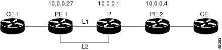
PE1 Configuration
mpls label protocol ldp
mpls traffic-eng tunnels
mpls ldp router-id Loopback1 force
!
pseudowire-class T41
 encapsulation mpls
 preferred-path interface Tunnel41 disable-fallback
!
pseudowire-class IP1
 encapsulation mpls
 preferred-path peer 10.4.0.1 disable-fallback
!
interface Loopback1
 ip address 10.0.0.27 255.255.255.255
!
interface Tunnel1
 ip unnumbered Loopback1
 tunnel destination 10.0.0.1
 tunnel mode mpls traffic-eng
 tunnel mpls traffic-eng priority 1 1
 tunnel mpls traffic-eng bandwidth 10000
 tunnel mpls traffic-eng path-option 1 explicit name FRR
!
interface Tunnel41
 ip unnumbered Loopback1
 tunnel destination 10.0.0.4
 tunnel mode mpls traffic-eng
 tunnel mpls traffic-eng priority 1 1
 tunnel mpls traffic-eng bandwidth 1000
 tunnel mpls traffic-eng path-option 1 explicit name name-1
 tunnel mpls traffic-eng fast-reroute
!
interface POS0/0
 description pe1name POS8/0/0
 ip address 10.1.0.2 255.255.255.252
 mpls traffic-eng tunnels
 mpls traffic-eng backup-path Tunnel1
 crc 16
 clock source internal
 pos ais-shut
 pos report lrdi
 ip rsvp bandwidth 155000 155000
!
interface POS0/3
 description pe1name POS10/1/0
 ip address 10.1.0.14 255.255.255.252
 mpls traffic-eng tunnels
 crc 16
 clock source internal
 ip rsvp bandwidth 155000 155000
!
interface gigabitethernet3/0.1
 encapsulation dot1Q 203
 xconnect 10.0.0.4 2 pw-class IP1
!
interface gigabitethernet3/0.2
 encapsulation dot1Q 204
 xconnect 10.0.0.4 4 pw-class T41
!
router ospf 1
 network 10.0.0.0 0.255.255.255 area 0
 mpls traffic-eng router-id Loopback1
 mpls traffic-eng area 0
!
ip classless
ip route 10.4.0.1 255.255.255.255 Tunnel41
!
ip explicit-path name xxxx-1 enable
 next-address 10.4.1.2
 next-address 10.1.0.10
P Configuration
ip cef
mpls traffic-eng tunnels
!
interface Loopback1
 ip address 10.0.0.1 255.255.255.255
!
interface FastEthernet1/0/0
 ip address 10.4.1.2 255.255.255.0
 mpls traffic-eng tunnels
 ip rsvp bandwidth 10000 10000
!
interface POS8/0/0
 description xxxx POS0/0
 ip address 10.1.0.1 255.255.255.252
 mpls traffic-eng tunnels
 pos ais-shut
 pos report lrdi
 ip rsvp bandwidth 155000 155000
!
interface POS10/1/0
 description xxxx POS0/3
 ip address 10.1.0.13 255.255.255.252
 mpls traffic-eng tunnels
 ip rsvp bandwidth 155000 155000
!
router ospf 1
 network 10.0.0.0 0.255.255.255 area 0
 mpls traffic-eng router-id Loopback1
 mpls traffic-eng area 0
PE2 Configuration
ip cef
mpls label protocol ldp
mpls traffic-eng tunnels
mpls ldp router-id Loopback1 force
!
interface Loopback1
 ip address 10.0.0.4 255.255.255.255
!
interface loopback 2
ip address 10.4.0.1 255.255.255.255
!
interface Tunnel27
 ip unnumbered Loopback1
 tunnel destination 10.0.0.27
 tunnel mode mpls traffic-eng
 tunnel mpls traffic-eng autoroute announce
 tunnel mpls traffic-eng priority 1 1
 tunnel mpls traffic-eng bandwidth 1000
 tunnel mpls traffic-eng path-option 1 explicit name xxxx-1
!
interface FastEthernet0/0.2
 encapsulation dot1Q 203
 xconnect 10.0.0.27 2 encapsulation mpls
!
interface FastEthernet0/0.3
 encapsulation dot1Q 204
 xconnect 10.0.0.27 4 encapsulation mpls
!
interface FastEthernet1/1
 ip address 10.4.1.1 255.255.255.0
 mpls traffic-eng tunnels
 ip rsvp bandwidth 10000 10000
!
router ospf 1
 network 10.0.0.0 0.255.255.255 area 0
 mpls traffic-eng router-id Loopback1
 mpls traffic-eng area 0
!
ip explicit-path name xxxx-1 enable
 next-address 10.4.1.2
 next-address 10.1.0.10
Example Configuring per-Subinterface MTU for Ethernet over MPLS
The figure below shows a configuration that enables matching MTU values between VC endpoints.
As shown in the figure below, PE1 is configured in xconnect subinterface configuration mode with an MTU value of 1500 bytes in order to establish an end-to-end VC with PE2, which also has an MTU value of 1500 bytes. If PE1 was not set with an MTU value of 1500 bytes, in xconnect subinterface configuration mode, the subinterface would inherit the MTU value of 2000 bytes set on the interface. This would cause a mismatch in MTU values between the VC endpoints, and the VC would not come up.
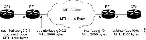
The following examples show the router configurations in the figure above:
CE1 Configuration
interface gigabitethernet0/0
 mtu 1500
 no ip address
!
interface gigabitethernet0/0.1
 encapsulation dot1Q 100
 ip address 10.181.182.1 255.255.255.0
PE1 Configuration
interface gigabitethernet0/0
 mtu 2000
 no ip address
!
interface gigabitethernet0/0.1
 encapsulation dot1Q 100
 xconnect 10.1.1.152 100 encapsulation mpls
  mtu 1500
!
interface gigabitethernet0/0.2
 encapsulation dot1Q 200
 ip address 10.151.100.1 255.255.255.0
 mpls ip
PE2 Configuration
interface gigabitethernet1/0
 mtu 2000
 no ip address
!
interface gigabitethernet1/0.2
 encapsulation dot1Q 200
 ip address 10.100.152.2 255.255.255.0
 mpls ip
!
interface fastethernet0/0
 no ip address
!
interface fastethernet0/0.1
 description default MTU of 1500 for FastEthernet
 encapsulation dot1Q 100
 xconnect 10.1.1.151 100 encapsulation mpls
CE2 Configuration
interface fastethernet0/0
 no ip address
interface fastethernet0/0.1
 encapsulation dot1Q 100
 ip address 10.181.182.2 255.255.255.0
The show mpls l2transport bindingcommand, issued from router PE1, shows a matching MTU value of 1500 bytes on both the local and remote routers:
Router# show mpls l2transport binding
Destination Address: 10.1.1.152,  VC ID: 100
    Local Label: 100
        Cbit: 1,    VC Type: Ethernet,    GroupID: 0
        MTU: 1500,   Interface Desc: n/a
        VCCV: CC Type: CW [1], RA [2]
              CV Type: LSPV [2]
    Remote Label: 202
        Cbit: 1,    VC Type: Ethernet,    GroupID: 0
        MTU: 1500,   Interface Desc: n/a
        VCCV: CC Type: RA [2]
              CV Type: LSPV [2]
Router# show mpls l2transport vc detail
Local interface: Gi0/0.1 up, line protocol up, Eth VLAN 100 up
  Destination address: 10.1.1.152, VC ID: 100, VC status: up
    Output interface: Gi0/0.2, imposed label stack {202}
    Preferred path: not configured
    Default path: active
    Next hop: 10.151.152.2
  Create time: 1d11h, last status change time: 1d11h
  Signaling protocol: LDP, peer 10.1.1.152:0 up
    Targeted Hello: 10.1.1.151(LDP Id) -> 10.1.1.152
    MPLS VC labels: local 100, remote 202
    Group ID: local 0, remote 0
    MTU: local 1500, remote 1500
    Remote interface description:
  Sequencing: receive disabled, send disabled
  VC statistics:
    packet totals: receive 41, send 39
    byte totals:   receive 4460, send 5346
    packet drops:  receive 0, send 0
In the following example, you are specifying an MTU of 1501 in xconnect subinterface configuration mode, and that value is out of range, the router enters the command in subinterface configuration mode, where it is accepted:
Router# configure terminal
router(config)# interface gigabitethernet0/2.1
router(config-subif)# xconnect 10.10.10.1 100 encapsulation mpls
router(config-subif-xconn)# mtu ?
<64 - 1500> MTU size in bytes
router(config-subif-xconn)# mtu 1501
router(config-subif)# mtu ?
<64 - 17940> MTU size in bytes
If the MTU value is not accepted in either xconnect subinterface configuration mode or subinterface configuration mode, then the command is rejected, as shown in the following example:
Router# configure terminal
router(config)# interface gigabitethernet0/2.1
router(config-subif)# xconnect 10.10.10.1 100 encapsulation mpls
router(config-subif-xconn)# mtu ?
<64 - 1500> MTU size in bytes
router(config-subif-xconn)# mtu 63
% Invalid input detected at ^ marker
Example Configuring MTU Values in xconnect Configuration Mode for L2VPN Interworking
The following example shows an L2VPN Interworking example. The PE1 router has a serial interface configured with an MTU value of 1492 bytes. The PE2 router uses xconnect configuration mode to set a matching MTU of 1492 bytes, which allows the two routers to form an interworking VC. If the PE2 router did not set the MTU value in xconnect configuration mode, the interface would be set to 1500 bytes by default and the VC would not come up.
PE1 Configuration
pseudowire-class atom-ipiw
 encapsulation mpls
 interworking ip
!
interface Loopback0
 ip address 10.1.1.151 255.255.255.255
!
interface Serial2/0
 mtu 1492
 no ip address
 encapsulation ppp
 no fair-queue
 serial restart-delay 0
 xconnect 10.1.1.152 123 pw-class atom-ipiw
!
interface Serial4/0
 ip address 10.151.100.1 255.255.255.252
 encapsulation ppp
 mpls ip
 serial restart-delay 0
!
router ospf 1
 log-adjacency-changes
 network 10.1.1.151 0.0.0.0 area 0
 network 10.151.100.0 0.0.0.3 area 0
!
mpls ldp router-id Loopback0
PE2 Configuration
pseudowire-class atom-ipiw
 encapsulation mpls
 interworking ip
!
interface Loopback0
 ip address 10.1.1.152 255.255.255.255
!
interface Ethernet0/0
 no ip address
 xconnect 10.1.1.151 123 pw-class atom-ipiw
  mtu 1492
!
interface Serial4/0
 ip address 10.100.152.2 255.255.255.252
 encapsulation ppp
 mpls ip
 serial restart-delay 0
!
router ospf 1
 log-adjacency-changes
 network 10.1.1.152 0.0.0.0 area 0
 network 10.100.152.0 0.0.0.3 area 0
!
mpls ldp router-id Loopback0
The show mpls l2transport bindingcommand shows that the MTU value for the local and remote routers is 1492 bytes.
PE1 Configuration
Router# show mpls l2transport binding

Destination Address: 10.1.1.152,  VC ID: 123
    Local Label: 105
        Cbit: 1,    VC Type: PPP,    GroupID: 0
        MTU: 1492,   Interface Desc: n/a
        VCCV: CC Type: CW [1], RA [2]
              CV Type: LSPV [2]
    Remote Label: 205
        Cbit: 1,    VC Type: Ethernet,    GroupID: 0
        MTU: 1492,   Interface Desc: n/a
        VCCV: CC Type: RA [2]
              CV Type: LSPV [2]
Router# show mpls l2transport vc detail
Local interface: Se2/0 up, line protocol up, PPP up
  MPLS VC type is PPP, interworking type is IP
  Destination address: 10.1.1.152, VC ID: 123, VC status: up
    Output interface: Se4/0, imposed label stack {1003 205}
    Preferred path: not configured
    Default path: active
    Next hop: point2point
  Create time: 00:25:29, last status change time: 00:24:54
  Signaling protocol: LDP, peer 10.1.1.152:0 up
    Targeted Hello: 10.1.1.151(LDP Id) -> 10.1.1.152
    Status TLV support (local/remote)   : enabled/supported
      Label/status state machine        : established, LruRru
      Last local dataplane   status rcvd: no fault
      Last local SSS circuit status rcvd: no fault
      Last local SSS circuit status sent: no fault
      Last local  LDP TLV    status sent: no fault
      Last remote LDP TLV    status rcvd: no fault
    MPLS VC labels: local 105, remote 205
    Group ID: local n/a, remote 0
    MTU: local 1492, remote 1492
    Remote interface description:
  Sequencing: receive disabled, send disabled
  VC statistics:
    packet totals: receive 30, send 29
    byte totals:   receive 2946, send 3364
    packet drops:  receive 0, send 0
PE2 Configuration
Router# show mpls l2transport binding

Destination Address: 10.1.1.151,  VC ID: 123
    Local Label: 205
        Cbit: 1,    VC Type: Ethernet,    GroupID: 0
        MTU: 1492,   Interface Desc: n/a
        VCCV: CC Type: RA [2]
              CV Type: LSPV [2]
    Remote Label: 105
        Cbit: 1,    VC Type: Ethernet,    GroupID: 0
        MTU: 1492,   Interface Desc: n/a
        VCCV: CC Type: CW [1], RA [2]
              CV Type: LSPV [2]
Router# show mpls l2transport vc detail
Local interface: Et0/0 up, line protocol up, Ethernet up
  MPLS VC type is Ethernet, interworking type is IP
  Destination address: 10.1.1.151, VC ID: 123, VC status: up
    Output interface: Se4/0, imposed label stack {1002 105}
    Preferred path: not configured
    Default path: active
    Next hop: point2point
  Create time: 00:25:19, last status change time: 00:25:19
  Signaling protocol: LDP, peer 10.1.1.151:0 up
    Targeted Hello: 10.1.1.152(LDP Id) -> 10.1.1.151
    Status TLV support (local/remote)   : enabled/supported
      Label/status state machine        : established, LruRru
      Last local dataplane   status rcvd: no fault
      Last local SSS circuit status rcvd: no fault
      Last local SSS circuit status sent: no fault
      Last local  LDP TLV    status sent: no fault
      Last remote LDP TLV    status rcvd: no fault
    MPLS VC labels: local 205, remote 105
    Group ID: local n/a, remote 0
    MTU: local 1492, remote 1492
    Remote interface description:
  Sequencing: receive disabled, send disabled
  VC statistics:
    packet totals: receive 29, send 30
    byte totals:   receive 2900, send 3426
    packet drops:  receive 0, send 0
Example Removing a Pseudowire
The following example shows how to remove all xconnects:
Router# clear xconnect all
02:13:56: Xconnect[ac:Et1/0.1(Eth VLAN)]: provisioning fwder with fwd_type=1, sss_role=1
02:13:56: Xconnect[mpls:10.1.1.2:1234000]: provisioning fwder with fwd_type=2, sss_role=2
02:13:56: Xconnect[ac:Et1/0.2(Eth VLAN)]: provisioning fwder with fwd_type=1, sss_role=2
02:13:56: Xconnect[mpls:10.1.1.2:1234001]: provisioning fwder with fwd_type=2, sss_role=1
02:13:56: Xconnect[ac:Et1/0.3(Eth VLAN)]: provisioning fwder with fwd_type=1, sss_role=1
02:13:56: Xconnect[mpls:10.1.2.2:1234002]: provisioning fwder with fwd_type=2, sss_role=2
02:13:56: Xconnect[ac:Et1/0.4(Eth VLAN)]: provisioning fwder with fwd_type=1, sss_role=2
02:13:56: Xconnect[mpls:10.1.2.2:1234003]: provisioning fwder with fwd_type=2, sss_role=1
02:13:56: MPLS peer 10.1.1.2 vcid 1234000, VC DOWN, VC state DOWN
02:13:56: MPLS peer 10.1.1.2 vcid 1234001, VC DOWN, VC state DOWN
02:13:56: MPLS peer 10.1.2.2 vcid 1234002, VC DOWN, VC state DOWN
02:13:56: MPLS peer 10.1.2.2 vcid 1234003, VC DOWN, VC state DOWN
02:13:56: XC AUTH [Et1/0.1, 1001]: Event: start xconnect authorization, state changed from IDLE to AUTHORIZING
02:13:56: XC AUTH [Et1/0.1, 1001]: Event: found xconnect authorization, state changed from AUTHORIZING to DONE
02:13:56: XC AUTH [Et1/0.3, 1003]: Event: start xconnect authorization, state changed from IDLE to AUTHORIZING
02:13:56: XC AUTH [Et1/0.3, 1003]: Event: found xconnect authorization, state changed from AUTHORIZING to DONE
02:13:56: XC AUTH [10.1.1.2, 1234001]: Event: start xconnect authorization, state changed from IDLE to AUTHORIZING
02:13:56: XC AUTH [10.1.1.2, 1234001]: Event: found xconnect authorization, state changed from AUTHORIZING to DONE
02:13:56: XC AUTH [10.1.2.2, 1234003]: Event: start xconnect authorization, state changed from IDLE to AUTHORIZING
02:13:56: XC AUTH [10.1.2.2, 1234003]: Event: found xconnect authorization, state changed from AUTHORIZING to DONE
02:13:56: XC AUTH [Et1/0.1, 1001]: Event: free xconnect authorization request, state changed from DONE to END
02:13:56: XC AUTH [Et1/0.3, 1003]: Event: free xconnect authorization request, state changed from DONE to END
02:13:56: XC AUTH [10.1.1.2, 1234001]: Event: free xconnect authorization request, state changed from DONE to END
02:13:56: XC AUTH [10.1.2.2, 1234003]: Event: free xconnect authorization request, state changed from DONE to END
02:13:56: MPLS peer 10.1.1.2 vcid 1234001, VC UP, VC state UP
02:13:56: MPLS peer 10.1.2.2 vcid 1234003, VC UP, VC state UP
02:13:56: MPLS peer 10.1.1.2 vcid 1234000, VC UP, VC state UP
02:13:56: MPLS peer 10.1.2.2 vcid 1234002, VC UP, VC state UP
The following example shows how to remove all the xconnects associated with peer router 10.1.1.2:
Router# clear xconnect peer 10.1.1.2 all
02:14:08: Xconnect[ac:Et1/0.1(Eth VLAN)]: provisioning fwder with fwd_type=1, sss_role=1
02:14:08: Xconnect[mpls:10.1.1.2:1234000]: provisioning fwder with fwd_type=2, sss_role=2
02:14:08: Xconnect[ac:Et1/0.2(Eth VLAN)]: provisioning fwder with fwd_type=1, sss_role=2
02:14:08: Xconnect[mpls:10.1.1.2:1234001]: provisioning fwder with fwd_type=2, sss_role=1
02:14:08: MPLS peer 10.1.1.2 vcid 1234000, VC DOWN, VC state DOWN
02:14:08: MPLS peer 10.1.1.2 vcid 1234001, VC DOWN, VC state DOWN
02:14:08: XC AUTH [Et1/0.1, 1001]: Event: start xconnect authorization, state changed from IDLE to AUTHORIZING
02:14:08: XC AUTH [Et1/0.1, 1001]: Event: found xconnect authorization, state changed from AUTHORIZING to DONE
02:14:08: XC AUTH [10.1.1.2, 1234001]: Event: start xconnect authorization, state changed from IDLE to AUTHORIZING
02:14:08: XC AUTH [10.1.1.2, 1234001]: Event: found xconnect authorization, state changed from AUTHORIZING to DONE
02:14:08: XC AUTH [Et1/0.1, 1001]: Event: free xconnect authorization request, state changed from DONE to END
02:14:08: XC AUTH [10.1.1.2, 1234001]: Event: free xconnect authorization request, state changed from DONE to END
02:14:08: MPLS peer 10.1.1.2 vcid 1234001, VC UP, VC state UP
02:14:08: MPLS peer 10.1.1.2 vcid 1234000, VC UP, VC state UP
The following example shows how to remove the xconnects associated with peer router 10.1.1.2 and VC ID 1234001:
Router# clear xconnect peer 10.1.1.2 vcid 1234001
02:14:23: Xconnect[ac:Et1/0.2(Eth VLAN)]: provisioning fwder with fwd_type=1, sss_role=1
02:14:23: Xconnect[mpls:10.1.1.2:1234001]: provisioning fwder with fwd_type=2, sss_role=2
02:14:23: MPLS peer 10.1.1.2 vcid 1234001, VC DOWN, VC state DOWN
02:14:23: XC AUTH [Et1/0.2, 1002]: Event: start xconnect authorization, state changed from IDLE to AUTHORIZING
02:14:23: XC AUTH [Et1/0.2, 1002]: Event: found xconnect authorization, state changed from AUTHORIZING to DONE
02:14:23: XC AUTH [Et1/0.2, 1002]: Event: free xconnect authorization request, state changed from DONE to END
02:14:23: MPLS peer 10.1.1.2 vcid 1234001, VC UP, VC state UP
The following example shows how to remove the xconnects associated with interface Ethernet 1/0.1:
Router# clear xconnect interface eth1/0.1

02:14:48: Xconnect[ac:Et1/0.1(Eth VLAN)]: provisioning fwder with fwd_type=1, sss_role=2
02:14:48: Xconnect[mpls:10.1.1.2:1234000]: provisioning fwder with fwd_type=2, sss_role=1
02:14:48: MPLS peer 10.1.1.2 vcid 1234000, VC DOWN, VC state DOWN
02:14:48: XC AUTH [10.1.1.2, 1234000]: Event: start xconnect authorization, state changed from IDLE to AUTHORIZING
02:14:48: XC AUTH [10.1.1.2, 1234000]: Event: found xconnect authorization, state changed from AUTHORIZING to DONE
02:14:48: XC AUTH [10.1.1.2, 1234000]: Event: free xconnect authorization request, state changed from DONE to END
Additional References
Related Documents
|
Related Topic |
Document Title |
|---|---|
|
Cisco IOS commands |
|
|
MPLS commands |
Cisco IOS Multiprotocol Label Switching Command Reference |
|
Any Transport over MPLS |
"Overview" section of Cisco Any Transport over MPLS |
|
Any Transport over MPLS for the Cisco 10000 series router |
Cisco 10000 Series Router Broadband Aggregation, Leased-Line, and MPLS Configuration Guide |
|
Layer 2 Tunnel Protocol Version 3 (L2TPv3) |
Layer 2 Tunnel Protocol Version 3 (L2TPv3) |
|
L2VPN interworking |
L2VPN Interworking |
MIBs
|
MIB |
MIBs Link |
|---|---|
|
ATM AAL5 over MPLS and ATM Cell Relay over MPLS:
Ethernet over MPLS:
Frame Relay over MPLS:
HDLC and PPP over MPLS: |
To locate and download MIBs for selected platforms, Cisco software releases, and feature sets, use Cisco MIB Locator found at the following URL: |
Technical Assistance
|
Description |
Link |
|---|---|
|
The Cisco Support and Documentation website provides online resources to download documentation, software, and tools. Use these resources to install and configure the software and to troubleshoot and resolve technical issues with Cisco products and technologies. Access to most tools on the Cisco Support and Documentation website requires a Cisco.com user ID and password. |
Feature Information for Any Transport over MPLS
The following table provides release information about the feature or features described in this module. This table lists only the software release that introduced support for a given feature in a given software release train. Unless noted otherwise, subsequent releases of that software release train also support that feature.
Use Cisco Feature Navigator to find information about platform support and Cisco software image support. To access Cisco Feature Navigator, go to www.cisco.com/go/cfn. An account on Cisco.com is not required.
| Table 9 | Feature Information for Any Transport over MPLS |
|
Feature Name |
Releases |
Feature Information |
|---|---|---|
|
Any Transport over MPLS |
12.0(10)ST 12.0(21)ST 12.0(22)S 12.0(23)S 12.0(25)S 12.0(26)S 12.0(27)S 12.0(29)S 12.0(30)S 12.0(31)S 12.0(32)S 12.1(8a)E 12.2(14)S 12.2(15)T 12.2(28)SB 12.2(33)SRB 12.2(33)SXH 12.2(33)SRC 12.2(33)SRD 12.2(1)SRE 12.4(11)T 15.0(1)S 15.1(3)S |
In Cisco IOS Release 12.0(10)ST, Any Transport over MPLS: ATM AAL5 over MPLS was introduced on the Cisco 12000 series routers. In Cisco IOS Release 12.1(8a)E, Ethernet over MPLS was introduced on the Cisco 7600 series Internet router. In Cisco IOS Release 12.0(21)ST, Any Transport over MPLS: Ethernet over MPLS was introduced on the Cisco 12000 series routers. ATM AAL5 over MPLS was updated. In Cisco IOS Release 12.0(22)S, Ethernet over MPLS was integrated into this release. Support for the Cisco 10720 Internet router was added. ATM AAL5 over MPLS was integrated into this release for the Cisco 12000 series routers. In Cisco IOS Release 12.0(23)S, the following new features were introduced and support was added for them on the Cisco 7200 and 7500 series routers:
Cisco IOS Release 12.0(23)S also added support on the Cisco 12000, 7200, and 7500 series routers for the following features: The AToM features were integrated into Cisco IOS Release 12.2(14)S. The AToM features were integrated into Cisco IOS Release 12.2(15)T. In Cisco IOS Release 12.0(25)S, the following new features were introduced:
|
|
In Cisco IOS Release 12.0(26)S, the following new features were introduced:
Support for FECN and BECN marking with Frame Relay over MPLS. (See BECN and FECN Marking for Frame Relay over MPLS for more information.) In Cisco IOS Release 12.0(27)S, the following new features were introduced:
This feature was integrated into Cisco IOS Release 12.2(25)S for the Cisco 7200 and 7500 series routers. In Cisco IOS Release 12.0(29)S, the "Any Transport over MPLS Sequencing Support" feature was added for the Cisco 7200 and 7500 series routers. In Cisco IOS Release 12.0(30)S, the following new features were introduced: In Cisco IOS Release 12.0(31)S, the Cisco 12000 series router introduced the following enhancements:
In Cisco IOS Release 12.0(32)S, the Cisco 12000 series router added engine 5 line card support for the following transport types: |
||
|
This feature was integrated into Cisco IOS Release 12.2(28)SB on the Cisco 10000 series routers. Platform-specific configuration information is contained in the "Configuring Any Transport over MPLS" section of the Cisco 10000 Series Router Broadband Aggregation, Leased-Line, and MPLS Configuration Guide. Any Transport over MPLS was integrated into Cisco IOS Release 12.4(11)T with support for the following features:
This feature was integrated into Cisco IOS Release 12.2(33)SRB to support the following features on the Cisco 7600 router:
Platform-specific configuration information is contained in the following documents:
|
||
|
This feature was integrated into Cisco IOS Release 12.2(33)SXH and supports the following features:
The following features were integrated into Cisco IOS Release 12.2(33)SRC:
In Cisco IOS Release 12.2(33)SRD, support for ATM Cell Relay over MPLS in port mode on Cisco 7600 series routers was added. Per Subinterface MTU for Ethernet over MPLS (EoMPLS) was integrated into Cisco IOS Release 15.1(3)S. |
||
|
MPLS L2VPN Clear Xconnect Command |
12.2(1)SRE 15.0(1)S |
These features are supported on Cisco 7600 routers in Cisco IOS Release 12.2(1)SRE and Cisco IOS Release 15.0(1)S. These features enable you to:
The following commands were introduced or modified by these features: cell-packing, clear xconnect, control-word, encapsulation (Any Transport over MPLS), oam-ac emulation-enable. |
|
MPLS MTU Command for GRE Tunnels |
15.1(1)T 15.1(2)S |
This feature allows you to reset the MPLS MTU size in GRE tunnels from default to the maximum. The maximum keyword was replaced with the max keyword. The following command was modified by this feature: mpls mtu. |
|
ATM Port mode Packed Cell Relay over MPLS |
15.2(1)S |
This feature was integrated into Cisco IOS Release 12.2(1)S. |
|
Any Transport over MPLS (AToM): ATM Cell Relay over MPLS: Packed Cell Relay |
15.2(1)S |
This feature was integrated into Cisco IOS Release 12.2(1)S. |
Cisco and the Cisco logo are trademarks or registered trademarks of Cisco and/or its affiliates in the U.S. and other countries. To view a list of Cisco trademarks, go to this URL: www.cisco.com/go/trademarks. Third-party trademarks mentioned are the property of their respective owners. The use of the word partner does not imply a partnership relationship between Cisco and any other company. (1110R)
Any Internet Protocol (IP) addresses and phone numbers used in this document are not intended to be actual addresses and phone numbers. Any examples, command display output, network topology diagrams, and other figures included in the document are shown for illustrative purposes only. Any use of actual IP addresses or phone numbers in illustrative content is unintentional and coincidental.