
 Feedback
Contents
- MPLS VPN Inter-AS with ASBRs Exchanging VPN-IPv4 Addresses
- Finding Feature Information
- Prerequisites for MPLS VPN Inter-AS with ASBRs Exchanging VPN-IPv4 Addresses
- Restrictions for MPLS VPN Inter-AS with ASBRs Exchanging VPN-IPv4 Addresses
- Information About MPLS VPN Inter-AS with ASBRs Exchanging VPN-IPv4 Addresses
- MPLS VPN Inter-AS Introduction
- Benefits of MPLS VPN Inter-AS
- Use of Inter-AS with ASBRs Exchanging VPN-IPv4 Addresses
- Information Exchange in an MPLS VPN Inter-AS with ASBRs Exchanging VPN-IPv4 Addresses
- Transmission of Information in an MPLS VPN Inter-AS with ASBRs Exchanging VPN-IPv4 Addresses
- Exchange of VPN Routing Information in an MPLS VPN Inter-AS with ASBRs Exchanging VPN-IPv4 Addresses
- Packet Forwarding Between MPLS VPN Inter-AS Systems with ASBRs Exchanging VPN-IPv4 Addresses
- Use of a Confederation for MPLS VPN Inter-AS with ASBRs Exchanging VPN-IPv4 Addresses
- How to Configure MPLS VPN Inter-AS with ASBRs Exchanging VPN-IPv4 Addresses
- Configuring the ASBRs to Exchange VPN-IPv4 Addresses
- Configuring EBGP Routing to Exchange VPN Routes Between Subautonomous Systems in a Confederation
- Verifying Inter-AS with ASBRs Exchanging VPN-IPv4 Addresses
- Configuration Examples for MPLS VPN Inter-AS with ASBRs Exchanging VPN-IPv4 Addresses
- Configuring MPLS VPN Inter-AS with ASBRs Exchanging VPN-IPv4 Addresses Example
- Configuration for Autonomous System 1 CE1 Example
- Configuration for Autonomous System 1 PE1 Example
- Configuration for Autonomous System 1 P1 Example
- Configuration for Autonomous System 1 EBGP1 Example
- Configuration for Autonomous System 2 EBGP2 Example
- Configuration for Autonomous System 2 P2 Example
- Configuration for Autonomous System 2 PE2 Example
- Configuration for Autonomous System 2 CE2 Example
- Configuring MPLS VPN Inter-AS with ASBRs Exchanging VPN-IPv4 Addresses in a Confederation Example
- Configuration for Autonomous System 1 CE1 Example
- Configuration for Autonomous System 1 PE1 Example
- Configuration for Autonomous System 1 P1 Example
- Configuration for Autonomous System 1 ASBR1 Example
- Configuration for Autonomous System 2 ASBR2 Example
- Configuration for Autonomous System 2 P2 Example
- Configuration for Autonomous System 2 PE2 Example
- Configuration for Autonomous System 2 CE2 Example
- Additional References
- Feature Information for MPLS VPN Inter-AS with ASBRs Exchanging VPN-IPv4 Addresses
MPLS VPN Inter-AS with ASBRs Exchanging VPN-IPv4 Addresses
The MPLS VPN Inter-AS with ASBRs Exchanging VPN-IPv4 Addresses feature allows a Multiprotocol Label Switching (MPLS) Virtual Private Network (VPN) to span service providers and autonomous systems. This module explains how to enable Autonomous System Boundary Routers (ASBRs) to use Exterior Border Gateway Protocol (EBGP) to exchange IPv4 Network Layer Reachability Information (NLRI) in the form of VPN-IPv4 addresses.
- Finding Feature Information
- Prerequisites for MPLS VPN Inter-AS with ASBRs Exchanging VPN-IPv4 Addresses
- Restrictions for MPLS VPN Inter-AS with ASBRs Exchanging VPN-IPv4 Addresses
- Information About MPLS VPN Inter-AS with ASBRs Exchanging VPN-IPv4 Addresses
- How to Configure MPLS VPN Inter-AS with ASBRs Exchanging VPN-IPv4 Addresses
- Configuration Examples for MPLS VPN Inter-AS with ASBRs Exchanging VPN-IPv4 Addresses
- Additional References
- Feature Information for MPLS VPN Inter-AS with ASBRs Exchanging VPN-IPv4 Addresses
Finding Feature Information
Your software release may not support all the features documented in this module. For the latest feature information and caveats, see the release notes for your platform and software release. To find information about the features documented in this module, and to see a list of the releases in which each feature is supported, see the Feature Information Table at the end of this document.
Use Cisco Feature Navigator to find information about platform support and Cisco software image support. To access Cisco Feature Navigator, go to www.cisco.com/go/cfn. An account on Cisco.com is not required.
Prerequisites for MPLS VPN Inter-AS with ASBRs Exchanging VPN-IPv4 Addresses
- Before you configure EBGP routing between autonomous systems or subautonomous systems in an MPLS VPN, ensure that you have properly configured all MPLS VPN routing instances and sessions. The configuration tasks outlined in this section build from those configuration tasks. Perform the following tasks as described in the Configuring MPLS Layer 3 VPNs module:
- This feature is supported on the Cisco 12000 series router line cards listed in the table below.
| Table 1 | Cisco 12000 Series Line Card Support Added for Cisco IOS Releases |
|
Type |
Line Cards |
Cisco IOS Release Added |
|---|---|---|
|
Packet over SONET (POS) |
4-Port OC-3 POS 1-Port OC-12 POS 8-Port OC-3 POS 16-Port OC-3 POS 4-Port OC-12 POS 1-Port OC-48 POS 4-Port OC-3 POS ISE 8-Port OC-3 POS ISE 16 x OC-3 POS ISE 4-Port OC-12 POS ISE 1-Port OC-48 POS ISE |
12.0(16)ST 12.0(17)ST 12.0(22)S |
|
Electrical interface |
6-Port DS3 12-Port DS3 6-Port E3 12-Port E3 |
12.0(21)ST 12.0(22)S |
|
Ethernet |
3-Port GbE 1-Port 10-GbE Modular GbE/FE |
12.0(23)S 12.0(24)S |
|
ATM |
4-Port OC-3 ATM 1-Port OC-12 ATM 4-Port OC-12 ATM 8-Port OC-3 ATM |
12.0(16)ST 12.0(17)ST 12.0(23)S |
|
Channelized interface |
2-Port CHOC-3 6-Port Ch T3 (DS1) 1-Port CHOC-12 (DS3) 1-Port CHOC-12 (OC-3) 4-Port CHOC-12 ISE 1-Port CHOC-48 ISE |
12.0(22)S |
Restrictions for MPLS VPN Inter-AS with ASBRs Exchanging VPN-IPv4 Addresses
Multihop VPN-IPv4 EBGP is not supported.
Information About MPLS VPN Inter-AS with ASBRs Exchanging VPN-IPv4 Addresses
- MPLS VPN Inter-AS Introduction
- Benefits of MPLS VPN Inter-AS
- Use of Inter-AS with ASBRs Exchanging VPN-IPv4 Addresses
- Information Exchange in an MPLS VPN Inter-AS with ASBRs Exchanging VPN-IPv4 Addresses
MPLS VPN Inter-AS Introduction
An autonomous system is a single network or group of networks that is controlled by a common system administration group and that uses a single, clearly defined routing protocol.
As VPNs grow, their requirements expand. In some cases, VPNs need to reside on different autonomous systems in different geographic areas. Also, some VPNs need to extend across multiple service providers (overlapping VPNs). Regardless of the complexity and location of the VPNs, the connection between autonomous systems must be seamless to the customer.
Benefits of MPLS VPN Inter-AS
An MPLS VPN Inter-AS provides the following benefits:
- Allows a VPN to cross more than one service provider backbone: Service providers running separate autonomous systems can jointly offer MPLS VPN services to the same customer. A VPN can begin at one customer site and traverse different VPN service provider backbones before arriving at another site of the same customer. Previously, MPLS VPN could travers only e a single BGP autonomous system service provider backbone. This feature allows multiple autonomous systems to form a continuous (and seamless) network between customer sites of a service provider.
- Allows a VPN to exist in different areas: A service provider can create a VPN in different geographic areas. Having all VPN traffic flow through one point (between the areas) allows for better rate control of network traffic between the areas.
- Allows confederations to optimize IBGP meshing: Internal Border Gateway Protocol (IBGP) meshing in an autonomous system is more organized and manageable. An autonomous system can be divided into multiple, separate subautonomous systems and then classify them into a single confederation (even though the entire VPN backbone appears as a single autonomous system). This capability allows a service provider to offer MPLS VPNs across the confederation because it supports the exchange of labeled VPN-IPv4 NLRI between the subautonomous systems that form the confederation.
Use of Inter-AS with ASBRs Exchanging VPN-IPv4 Addresses
Separate autonomous systems from different service providers can communicate by exchanging IPv4 NLRI in the form of VPN-IPv4 addresses. The ASBRs use EBGP to exchange that information. Then an Interior Gateway Protocol (IGP) distributes the network layer information for VPN-IPv4 prefixes throughout each VPN and each autonomous system. Routing information uses the following protocols:
- Within an autonomous system, routing information is shared using an IGP.
- Between autonomous systems, routing information is shared using an EBGP. An EBGP allows a service provider to set up an interdomain routing system that guarantees the loop-free exchange of routing information between separate autonomous systems.
The primary function of an EBGP is to exchange network reachability information between autonomous systems, including information about the list of autonomous system routes. The autonomous systems use EBGP border edge routers to distribute the routes, which include label switching information. Each border edge router rewrites the next hop and labels. See the Information Exchange in an MPLS VPN Inter-AS with ASBRs Exchanging VPN-IPv4 Addresses section for more information.
Interautonomous system configurations supported in an MPLS VPN are as follows:
- Interprovider VPN-- MPLS VPNs that include two or more autonomous systems, connected by separate border edge routers. The autonomous systems exchange routes using EBGP. No IGP or routing information is exchanged between the autonomous systems.
- BGP confederations-- MPLS VPNs that divide a single autonomous system into multiple subautonomous systems, and classify them as a single, designated confederation. The network recognizes the confederation as a single autonomous system. The peers in the different autonomous systems communicate over EBGP sessions; however, they can exchange route information as if they were IBGP peers.
Information Exchange in an MPLS VPN Inter-AS with ASBRs Exchanging VPN-IPv4 Addresses
This section contains the following topics:
- Transmission of Information in an MPLS VPN Inter-AS with ASBRs Exchanging VPN-IPv4 Addresses
- Exchange of VPN Routing Information in an MPLS VPN Inter-AS with ASBRs Exchanging VPN-IPv4 Addresses
- Packet Forwarding Between MPLS VPN Inter-AS Systems with ASBRs Exchanging VPN-IPv4 Addresses
- Use of a Confederation for MPLS VPN Inter-AS with ASBRs Exchanging VPN-IPv4 Addresses
Transmission of Information in an MPLS VPN Inter-AS with ASBRs Exchanging VPN-IPv4 Addresses
The figure below illustrates one MPLS VPN consisting of two separate autonomous systems. Each autonomous system operates under different administrative control and runs a different IGP. Service providers exchange routing information through EBGP border edge routers (ASBR1, ASBR2).
| Figure 1 | EBGP Connection Between Two MPLS VPN Inter-AS Systems with ASBRs Exchanging VPN-IPv4 Addresses |
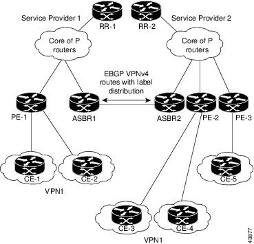
This configuration uses the following process to transmit information:
DETAILED STEPS
Exchange of VPN Routing Information in an MPLS VPN Inter-AS with ASBRs Exchanging VPN-IPv4 Addresses
Autonomous systems exchange VPN routing information (routes and labels) to establish connections. To control connections between autonomous systems, the PE routers and EBGP border edge routers maintain a Label Forwarding Information Base (LFIB). The LFIB manages the labels and routes that the PE routers and EBGP border edge routers receive during the exchange of VPN information.
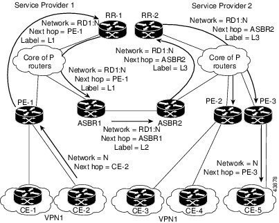
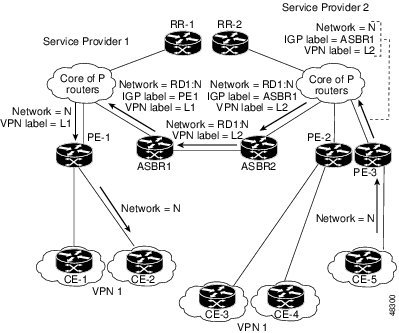
The figure below illustrates the exchange of VPN route and label information between autonomous systems. The autonomous systems use the following conditions to exchange VPN routing information:
- Routing information includes:
- An RD1: route distinguisher is part of a destination network address. It makes the VPN-IPv4 route globally unique in the VPN service provider environment.
- The ASBRs are configured to change the next-hop (next hop-self) when sending VPN-IPv4 NLRIs to the IBGP neighbors. Therefore, the ASBRs must allocate a new label when they forward the NLRI to the IBGP neighbors.
| Figure 2 | Exchanging Routes and Labels Between MPLS VPN Inter-AS Systems with ASBRs Exchanging VPN-IPv4 Addresses |
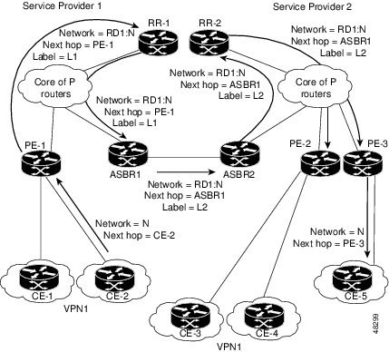
The figure below illustrates the exchange of VPN route and label information between autonomous systems. The only difference is that ASBR2 is configured with the redistribute connected command, which propagates the host routes to all PEs. The redistribute connected command is necessary because ASBR2 is not configured to change the next-hop address.
Packet Forwarding Between MPLS VPN Inter-AS Systems with ASBRs Exchanging VPN-IPv4 Addresses
The figure below illustrates how packets are forwarded between autonomous systems in an interprovider network using the following packet forwarding method.
Packets are forwarded to their destination by means of MPLS. Packets use the routing information stored in the LFIB of each PE router and EBGP border edge router.
The service provider VPN backbone uses dynamic label switching to forward labels.
Each autonomous system uses standard multilevel labeling to forward packets between the edges of the autonomous system routers (for example, from CE-5 to PE-3). Between autonomous systems, only a single level of labeling is used, corresponding to the advertised route.
A data packet carries two levels of labels when traversing the VPN backbone:
- The first label (IGP route label) directs the packet to the correct PE router or EBGP border edge router. (For example, the IGP label of ASBR2 points to the ASBR2 border edge router.)
- The second label (VPN route label) directs the packet to the appropriate PE router or EBGP border edge router.
| Figure 4 | Forwarding Packets Between MPLS VPN Inter-AS Systems with ASBRs Exchanging VPN-IPv4 Addresses |
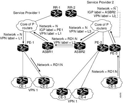
The figure below shows the same packet forwarding method as described in the figure above, except the EBGP router (ASBR1) forwards the packet without reassigning it a new label.
Use of a Confederation for MPLS VPN Inter-AS with ASBRs Exchanging VPN-IPv4 Addresses
A confederation is multiple subautonomous systems grouped together. A confederation reduces the total number of peer devices in an autonomous system. A confederation divides an autonomous system into subautonomous systems and assigns a confederation identifier to the autonomous systems. A VPN can span service providers running in separate autonomous systems or in multiple subautonomous systems that form a confederation.
In a confederation, each subautonomous system is fully meshed with other subautonomous systems. The subautonomous systems communicate using an IGP, such as Open Shortest Path First (OSPF) or Intermediate System-to-Intermediate System (IS-IS). Each subautonomous system also has an EBGP connection to the other subautonomous systems. The confederation EBGP (CEBGP) border edge routers forward next-hop-self addresses between the specified subautonomous systems. The next-hop-self address forces the BGP to use a specified address as the next hop rather than letting the protocol choose the next hop.
You can configure a confederation with separate subautonomous systems in either of two ways:
- You can configure a router to forward next-hop-self addresses between only the CEBGP border edge routers (both directions). The subautonomous systems (IBGP peers) at the subautonomous system border do not forward the next-hop-self address. Each subautonomous system runs as a single IGP domain. However, the CEBGP border edge router addresses are known in the IGP domains.
- You can configure a router to forward next-hop-self addresses between the CEBGP border edge routers (both directions) and within the IBGP peers at the subautonomous system border. Each subautonomous system runs as a single IGP domain but also forwards next-hop-self addresses between the PE routers in the domain. The CEBGP border edge router addresses are known in the IGP domains.

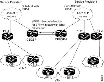
The figure below illustrates a typical MPLS VPN confederation configuration. In this confederation configuration:
- The two CEBGP border edge routers exchange VPN-IPv4 addresses with labels between the two subautonomous systems.
- The distributing router changes the next-hop addresses and labels and uses a next-hop-self address.
- IGP-1 and IGP-2 know the addresses of CEBGP-1 and CEBGP-2.
In this confederation configuration:
- CEBGP border edge routers function as neighboring peers between the subautonomous systems. The subautonomous systems use EBGP to exchange route information.
- Each CEBGP border edge router (CEBGP-1, CEBGP-2) assigns a label for the route before distributing the route to the next subautonomous system. The CEBGP border edge router distributes the route as a VPN-IPv4 address by using the multiprotocol extensions of BGP. The label and the VPN identifier are encoded as part of the NLRI.
- Each PE and CEBGP border edge router assigns its own label to each VPN-IPv4 address prefix before redistributing the routes. The CEBGP border edge routers exchange VPN-IPv4 addresses with the labels. The next-hop-self address is included in the label (as the value of the EBGP next-hop attribute). Within the subautonomous systems, the CEBGP border edge router address is distributed throughout the IBGP neighbors, and the two CEBGP border edge routers are known to both confederations.
How to Configure MPLS VPN Inter-AS with ASBRs Exchanging VPN-IPv4 Addresses
- Configuring the ASBRs to Exchange VPN-IPv4 Addresses
- Configuring EBGP Routing to Exchange VPN Routes Between Subautonomous Systems in a Confederation
- Verifying Inter-AS with ASBRs Exchanging VPN-IPv4 Addresses
Configuring the ASBRs to Exchange VPN-IPv4 Addresses
To configure an EBGP ASBR to exchange VPN-IPv4 routes with another autonomous system, perform this task.
DETAILED STEPS
Configuring EBGP Routing to Exchange VPN Routes Between Subautonomous Systems in a Confederation
Perform this task to configure EBGP routing to exchange VPN routes between subautonomous systems in a confederation.
DETAILED STEPS
Verifying Inter-AS with ASBRs Exchanging VPN-IPv4 Addresses
DETAILED STEPS
Examples
The sample output from the show mpls forwarding-table command shows how the VPN-IPv4 LFIB entries appear:
Router# show mpls forwarding-table
Local Outgoing      Prefix            Bytes tag Outgoing       Next Hop
tag   tag or VC     or Tunnel Id      switched  interface
33    33            10.120.4.0/24     0         Hs0/0         point2point
35    27            100:12:10.200.0.1/32 \
                                      0         Hs0/0         point2point
In this example, the Prefix field appears as a VPN-IPv4 RD, plus the prefix. If the value is longer than the width of the Prefix column (as illustrated in the last line of the example), the output automatically wraps onto the next line in the forwarding table, preserving column alignment.
Configuration Examples for MPLS VPN Inter-AS with ASBRs Exchanging VPN-IPv4 Addresses
- Configuring MPLS VPN Inter-AS with ASBRs Exchanging VPN-IPv4 Addresses Example
- Configuring MPLS VPN Inter-AS with ASBRs Exchanging VPN-IPv4 Addresses in a Confederation Example
Configuring MPLS VPN Inter-AS with ASBRs Exchanging VPN-IPv4 Addresses Example
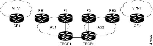
The network topology in the figure below shows two autonomous systems, which are configured as follows:
- Autonomous system 1 (AS1) includes PE1, P1, and EBGP1. The IGP is OSPF.
- Autonomous system 2 (AS2) includes PE2, P2, and EBGP2. The IGP is IS-IS.
- CE1 and CE2 belong to the same VPN, which is called VPN1.
- The P routers are route reflectors.
- EBGP1 is configured with the redistribute connected subnets command.
- EBGP2 is configured with the neighbor next-hop-self command.
- Configuration for Autonomous System 1 CE1 Example
- Configuration for Autonomous System 1 PE1 Example
- Configuration for Autonomous System 1 P1 Example
- Configuration for Autonomous System 1 EBGP1 Example
- Configuration for Autonomous System 2 EBGP2 Example
- Configuration for Autonomous System 2 P2 Example
- Configuration for Autonomous System 2 PE2 Example
- Configuration for Autonomous System 2 CE2 Example
Configuration for Autonomous System 1 CE1 Example
The following example shows how to configure CE1 in VPN1 in a topology with two autonomous systems (see the figure above):
CE1: Burlington
!
interface Loopback1
 ip address aa.0.0.6 255.255.255.255
!
interface Serial1/3
 description wychmere
 no ip address
 encapsulation frame-relay
 frame-relay intf-type dce
!
interface Serial1/3.1 point-to-point
 description wychmere
 ip address aa.6.2.1 255.255.255.252
 frame-relay interface-dlci 22
!
router ospf 1
 network aa.0.0.0 0.255.255.255 area 0
Configuration for Autonomous System 1 PE1 Example
The following example shows how to configure PE1 in AS1 in a topology with two autonomous systems (see the figure above):
PE1: wychmere
!
ip cef
!
ip vrf V1
 rd 1:105
 route-target export 1:100
 route-target import 1:100
!
interface Serial0/0
 description Burlington
 no ip address
 encapsulation frame-relay
 no fair-queue
 clockrate 2000000
!
interface Serial0/0.3 point-to-point
 description Burlington
 ip vrf forwarding V1
 ip address aa.6.2.2 255.255.255.252
 frame-relay interface-dlci 22
!
interface Ethernet0/1
 description Vermont
 ip address aa.2.2.5 255.255.255.0
 tag-switching ip
!
router ospf 1
 log-adjacency-changes
 network aa.0.0.0 0.255.255.255 area 0
!
router ospf 10 vrf V1
 log-adjacency-changes
 redistribute bgp 1 metric 100 subnets
 network aa.0.0.0 0.255.255.255 area 0
!
router bgp 1
 no synchronization
 neighbor 1 peer-group
 neighbor 1 remote-as 1
 neighbor 1 update-source Loopback0
 neighbor aa.0.0.2 peer-group R
 no auto-summary
 !
 address-family ipv4 vrf V1
  redistribute ospf 10
  no auto-summary
  no synchronization
  exit-address-family
 !
 address-family vpnv4
  neighbor R activate
  neighbor R send-community extended
  neighbor aa.0.0.2 peer-group R
  no auto-summary
  exit-address-family
Configuration for Autonomous System 1 P1 Example
The following example shows how to configure P1 in AS1 in a topology with two autonomous systems (see the figure above):
P1: Vermont
!
ip cef
!
interface Loopback0
 ip address aa.0.0.2 255.255.255.255
!
interface Ethernet0/1
 description Ogunquit
 ip address aa.2.1.1 255.255.255.0
 tag-switching ip
!
interface FastEthernet2/0
 description wychmere
 ip address aa.2.2.1 255.255.255.0
 duplex auto
 speed auto
 tag-switching ip
!
router ospf 1
 log-adjacency-changes
 network aa.0.0.0 0.255.255.255 area 0
!
router bgp 1
 no synchronization
 bgp log-neighbor-changes
 neighbor R peer-group
 neighbor R remote-as 1
 neighbor R update-source Loopback0
 neighbor R route-reflector-client
 neighbor aa.0.0.4 peer-group R
 neighbor aa.0.0.5 peer-group R
 !
 address-family vpnv4
  neighbor R activate
  neighbor R route-reflector-client
  neighbor R send-community extended
  neighbor aa.0.0.4 peer-group R
  neighbor aa.0.0.5 peer-group R
  exit-address-family
Configuration for Autonomous System 1 EBGP1 Example
The following example shows how to configure EBGP1 in AS1 in a topology with two autonomous systems (see the figure above):
EBGP1: Ogunquit
!
ip cef
!
interface Loopback0
 ip address aa.0.0.4 255.255.255.255
!
EBGP1: Ogunquit
!
ip cef
!
interface Loopback0
 ip address aa.0.0.4 255.255.255.255
!
interface Ethernet0/1
 description Vermont
 ip address aa.2.1.40 255.255.255.0
 tag-switching ip
!
interface ATM1/0
 description Lowell
 no ip address
 no atm scrambling cell-payload
 no atm ilmi-keepalive
!
interface ATM1/0.1 point-to-point
 description Lowell
 ip address aa.0.0.1 255.255.255.252
 pvc 1/100
!
router ospf 1
 log-adjacency-changes
 redistribute connected subnets
 network aa.0.0.0 0.255.255.255 area 0
!
router bgp 1
 no synchronization
 no bgp default route-target filter
 bgp log-neighbor-changes
 neighbor R peer-group
 neighbor R remote-as 1
 neighbor R update-source Loopback0
 neighbor aa.0.0.2 remote-as 2
 neighbor aa.0.0.2 peer-group R
 no auto-summary
 !
 address-family vpnv4
  neighbor R activate
  neighbor R send-community extended
  neighbor aa.0.0.2 activate
  neighbor aa.0.0.2 send-community extended
  neighbor aa.0.0.2 peer-group R
  no auto-summary
  exit-address-family
Configuration for Autonomous System 2 EBGP2 Example
The following example shows how to configure EBGP2 in AS2 in a topology with two autonomous systems (see the figure above):
EBGP2: Lowell
!
ip cef
!
ip vrf V1
 rd 2:103
 route-target export 1:100
 route-target import 1:100
!
interface Loopback0
 ip address aa.0.0.3 255.255.255.255
 ip router isis
!
interface Loopback1
 ip vrf forwarding V1
 ip address aa.0.0.3 255.255.255.255
!
interface Serial0/0
 description Littleton
 no ip address
 encapsulation frame-relay
 load-interval 30
 no fair-queue
 clockrate 2000000
!
interface Serial0/0.2 point-to-point
 description Littleton
 ip unnumbered Loopback0
 ip router isis
 tag-switching ip
 frame-relay interface-dlci 23
!
interface ATM1/0
 description Ogunquit
 no ip address
 atm clock INTERNAL
 no atm scrambling cell-payload
 no atm ilmi-keepalive
!
interface ATM1/0.1 point-to-point
 description Ogunquit
 ip address aa.0.0.2 255.255.255.252
 pvc 1/100
!
router isis
 net 49.0002.0000.0000.0003.00
!
router bgp 2
 no synchronization
 no bgp default route-target filter
 bgp log-neighbor-changes
 neighbor aa.0.0.1 remote-as 1
 neighbor aa.0.0.8 remote-as 2
 neighbor aa.0.0.8 update-source Loopback0
 neighbor aa.0.0.8 next-hop-self
!
 address-family ipv4 vrf V1
  redistribute connected
  no auto-summary
  no synchronization
  exit-address-family
 !
 address-family vpnv4
  neighbor aa.0.0.1 activate
  neighbor aa.0.0.1 send-community extended
  neighbor aa.0.0.8 activate
  neighbor aa.0.0.8 next-hop-self
  neighbor aa.0.0.8 send-community extended
  exit-address-family
Configuration for Autonomous System 2 P2 Example
The following example shows how to configure P2 in AS2 in a topology with two autonomous systems (see the figure above):
P2: Littleton
!
ip cef
!
ip vrf V1
 rd 2:108
 route-target export 1:100
 route-target import 1:100
!
interface Loopback0
 ip address aa.0.0.8 255.255.255.255
 ip router isis
!
interface Loopback1
 ip vrf forwarding V1
 ip address aa.0.0.8 255.255.255.255
!
interface FastEthernet0/0
 description Pax
 ip address aa.9.1.2 255.255.255.0
 ip router isis
 tag-switching ip
!
interface Serial5/0
 description Lowell
 no ip address
 encapsulation frame-relay
 frame-relay intf-type dce
!
interface Serial5/0.1 point-to-point
 description Lowell
 ip unnumbered Loopback0
 ip router isis
 tag-switching ip
 frame-relay interface-dlci 23
!
router isis
 net aa.0002.0000.0000.0008.00
!
router bgp 2
 no synchronization
 bgp log-neighbor-changes
 neighbor R peer-group
 neighbor R remote-as 2
 neighbor R update-source Loopback0
 neighbor R route-reflector-client
 neighbor aa.0.0.3 peer-group R
 neighbor aa.0.0.9 peer-group R
 !
 address-family ipv4 vrf V1
  redistribute connected
  no auto-summary
  no synchronization
  exit-address-family
 !
 address-family vpnv4
  neighbor R activate
  neighbor R route-reflector-client
  neighbor R send-community extended
  neighbor aa.0.0.3 peer-group R
  neighbor aa.0.0.9 peer-group R
  exit-address-family
Configuration for Autonomous System 2 PE2 Example
The following example shows how to configure PE2 in AS2 in a topology with two autonomous systems (see the figure above):
PE2: Pax
!
ip cef
!
ip vrf V1
 rd 2:109
 route-target export 1:100
 route-target import 1:100
!
interface Loopback0
 ip address aa.0.0.9 255.255.255.255
 ip router isis
!
interface Loopback1
 ip vrf forwarding V1
 ip address aa.0.0.9 255.255.255.255
!
interface Serial0/0
 description Bethel
 no ip address
 encapsulation frame-relay
 frame-relay intf-type dce
 no fair-queue
 clockrate 2000000
!
interface Serial0/0.1 point-to-point
 description Bethel
 ip vrf forwarding V1
 ip unnumbered Loopback1
 frame-relay interface-dlci 24
!
interface FastEthernet0/1
 description Littleton
 ip address aa.9.1.1 255.255.255.0
 ip router isis
 tag-switching ip
!
router ospf 10 vrf V1
 log-adjacency-changes
 redistribute bgp 2 subnets
 network aa.0.0.0 0.255.255.255 area 0
!
router isis
 net 49.0002.0000.0000.0009.00
!
router bgp 2
 no synchronization
 bgp log-neighbor-changes
 neighbor aa.0.0.8 remote-as 2
 neighbor aa.0.0.8 update-source Loopback0
 !
 address-family ipv4 vrf V1
  redistribute connected
  redistribute ospf 10
  no auto-summary
  no synchronization
  exit-address-family
 !
 address-family vpnv4
  neighbor aa.0.0.8 activate
  neighbor aa.0.0.8 send-community extended
  exit-address-family v
Configuration for Autonomous System 2 CE2 Example
The following example shows how to configure CE2 in VPN1 in a topology with two autonomous systems (see the figure above):
CE2: Bethel
!
interface Loopback0
 ip address 1.0.0.11 255.255.255.255
!
interface Serial0
 description Pax
 no ip address
 encapsulation frame-relay
 no fair-queue
 clockrate 2000000
!
interface Serial0.1 point-to-point
 description Pax
 ip unnumbered Loopback0
 frame-relay interface-dlci 24
!
router ospf 1
 network aa.0.0.0 0.255.255.255 area 0
Configuring MPLS VPN Inter-AS with ASBRs Exchanging VPN-IPv4 Addresses in a Confederation Example
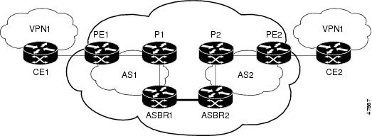
The network topology in the figure below shows a single internet service provider, which is partitioning the backbone with confederations. The autonomous system number of the provider is 100. The two autonomous systems run their own IGPs and are configured as follows:
- Autonomous system 1 (AS1) includes PE1, P1, ASBR1. The IGP is OSPF.
- Autonomous system 2 (AS2) includes PE2, P2, ASBR2. The IGP is IS-IS.
- CE1 and CE2 belong to the same VPN, which is called VPN1.
- The P routers are route reflectors.
- ASBR1 is configured with the redistribute connected subnets command.
- ASBR2 is configured with the neighbor next-hop-selfcommand.
- Configuration for Autonomous System 1 CE1 Example
- Configuration for Autonomous System 1 PE1 Example
- Configuration for Autonomous System 1 P1 Example
- Configuration for Autonomous System 1 ASBR1 Example
- Configuration for Autonomous System 2 ASBR2 Example
- Configuration for Autonomous System 2 P2 Example
- Configuration for Autonomous System 2 PE2 Example
- Configuration for Autonomous System 2 CE2 Example
Configuration for Autonomous System 1 CE1 Example
The following example shows how to configure CE1 in VPN1 in a confederation topology (see the figure above):
CE1: Burlington
!
interface Loopback1
 ip address aa.0.0.6 255.255.255.255
!
interface Serial1/3
 description wychmere
 no ip address
 encapsulation frame-relay
 frame-relay intf-type dce
!
interface Serial1/3.1 point-to-point
 description wychmere
 ip address aa.6.2.1 255.255.255.252
 frame-relay interface-dlci 22
!
router ospf 1
 network aa.0.0.0 0.255.255.255 area 0
Configuration for Autonomous System 1 PE1 Example
The following example shows how to configure PE1 in AS1 in a confederation topology (see the figure above):
PE1: wychmere
!
ip cef
!
ip vrf V1
 rd 1:105
 route-target export 1:100
 route-target import 1:100
!
interface Serial0/0
 description Burlington
 no ip address
 encapsulation frame-relay
 no fair-queue
 clockrate 2000000
!
interface Serial0/0.3 point-to-point
 description Burlington
 ip vrf forwarding V1
 ip address aa.6.2.2 255.255.255.252
 frame-relay interface-dlci 22
!
interface Ethernet0/1
 description Vermont
 ip address aa.2.2.5 255.255.255.0
 tag-switching ip
!
router ospf 1
 log-adjacency-changes
 network aa.0.0.0 0.255.255.255 area 0
!
router ospf 10 vrf V1
 log-adjacency-changes
 redistribute bgp 1 metric 100 subnets
 network aa.0.0.0 0.255.255.255 area 0
!
router bgp 1
 no synchronization
 bgp confederation identifier 100
 bgp confederation identifier 100
 neighbor 1 peer-group
 neighbor 1 remote-as 1
 neighbor 1 update-source Loopback0
 neighbor aa.0.0.2 peer-group R
 no auto-summary
 !
 address-family ipv4 vrf V1
  redistribute ospf 10
  no auto-summary
  no synchronization
  exit-address-family
 !
 address-family vpnv4
  neighbor R activate
  neighbor R send-community extended
  neighbor aa.0.0.2 peer-group R
  no auto-summary
  exit-address-family
Configuration for Autonomous System 1 P1 Example
The following example shows how to configure P1 in AS1 in a confederation topology (see the figure above):
P1: Vermont
!
ip cef
!
interface Loopback0
 ip address aa.0.0.2 255.255.255.255
!
interface Ethernet0/1
 description Ogunquit
 ip address 100.2.1.1 255.255.255.0
 tag-switching ip
!
interface FastEthernet2/0
 description wychmere
 ip address aa.2.2.1 255.255.255.0
 duplex auto
 speed auto
 tag-switching ip
!
router ospf 1
 log-adjacency-changes
 network aa.0.0.0 0.255.255.255 area 0
!
router bgp 1
 no synchronization
 bgp log-neighbor-changes
 bgp confederation identifier 100
 neighbor R peer-group
 neighbor R remote-as 1
 neighbor R update-source Loopback0
 neighbor R route-reflector-client
 neighbor 100.0.0.4 peer-group R
 neighbor 100.0.0.5 peer-group R
 !
 address-family vpnv4
  neighbor R activate
  neighbor R route-reflector-client
  neighbor R send-community extended
  neighbor aa.0.0.4 peer-group R
  neighbor aa.0.0.5 peer-group R
  exit-address-family
Configuration for Autonomous System 1 ASBR1 Example
The following example shows how to configure ASBR1 in AS1 in a confederation topology (see the figure above):
EBGP1: Ogunquit
!
ip cef
!
interface Loopback0
 ip address aa.0.0.4 255.255.255.255
!
interface Ethernet0/1
 description Vermont
 ip address aa.2.1.40 255.255.255.0
 tag-switching ip
!
interface ATM1/0
 description Lowell
 no ip address
 no atm scrambling cell-payload
 no atm ilmi-keepalive
!
interface ATM1/0.1 point-to-point
 description Lowell
 ip address aa.0.0.1 255.255.255.252
 pvc 1/100
!
router ospf 1
 log-adjacency-changes
 redistribute connected subnets
 network aa.0.0.0 0.255.255.255 area 0
!
router bgp 1
 no synchronization
 no bgp default route-target filter
 bgp log-neighbor-changes
 bgp confederation identifier 100
 bgp confederation peers 1
 neighbor R peer-group
 neighbor R remote-as 1
 neighbor R update-source Loopback0
 neighbor aa.0.0.2 remote-as 2
 neighbor aa.0.0.2 next-hop-self
 neighbor aa.0.0.2 peer-group R
 no auto-summary
 !
 address-family vpnv4
  neighbor R activate
  neighbor R send-community extended
  neighbor aa.0.0.2 activate
  neighbor aa.0.0.2 next-hop-self
  neighbor aa.0.0.2 send-community extended
  neighbor aa.0.0.2 peer-group R
  no auto-summary
  exit-address-family
Configuration for Autonomous System 2 ASBR2 Example
The following example shows how to configure ASBR2 in AS2 in a confederation topology (see the figure above):
EBGP2: Lowell
!
ip cef
!
ip vrf V1
 rd 2:103
 route-target export 1:100
 route-target import 1:100
!
interface Loopback0
 ip address aa.0.0.3 255.255.255.255
 ip router isis
!
interface Loopback1
 ip vrf forwarding V1
 ip address aa.0.0.3 255.255.255.255
!
interface Serial0/0
 description Littleton
 no ip address
 encapsulation frame-relay
 load-interval 30
 no fair-queue
 clockrate 2000000
!
interface Serial0/0.2 point-to-point
 description Littleton
 ip unnumbered Loopback0
 ip router isis
 tag-switching ip
 frame-relay interface-dlci 23
!
interface ATM1/0
 description Ogunquit
 no ip address
 atm clock INTERNAL
 no atm scrambling cell-payload
 no atm ilmi-keepalive
!
interface ATM1/0.1 point-to-point
 description Ogunquit
 ip address aa.0.0.2 255.255.255.252
 pvc 1/100
!
router isis
 net aa.0002.0000.0000.0003.00
!
router bgp 2
 no synchronization
 no bgp default route-target filter
 bgp log-neighbor-changes
 bgp confederation identifier 100
 bgp confederation peers 1
 neighbor aa.0.0.1 remote-as 1
 neighbor aa.0.0.1 next-hop-self
 neighbor aa.0.0.8 remote-as 2
 neighbor aa.0.0.8 update-source Loopback0
 neighbor aa.0.0.8 next-hop-self
 !
 address-family ipv4 vrf V1
  redistribute connected
  no auto-summary
  no synchronization
  exit-address-family
 !
 address-family vpnv4
  neighbor aa.0.0.1 activate
  neighbor aa.0.0.1 next-hop-self
  neighbor aa.0.0.1 send-community extended
  neighbor aa.0.0.8 activate
  neighbor aa.0.0.8 next-hop-self
  neighbor aa.0.0.8 send-community extended
  exit-address-family
Configuration for Autonomous System 2 P2 Example
The following example shows how to configure P2 in AS2 in a confederation topology (see the figure above):
P2: Littleton
!
ip cef
!
ip vrf V1
 rd 2:108
 route-target export 1:100
 route-target import 1:100
!
interface Loopback0
 ip address aa.0.0.8 255.255.255.255
 ip router isis
!
interface Loopback1
 ip vrf forwarding V1
 ip address aa.0.0.8 255.255.255.255
!
interface FastEthernet0/0
 description Pax
 ip address aa.9.1.2 255.255.255.0
 ip router isis
 tag-switching ip
!
interface Serial5/0
 description Lowell
 no ip address
 encapsulation frame-relay
 frame-relay intf-type dce
!
interface Serial5/0.1 point-to-point
 description Lowell
 ip unnumbered Loopback0
 ip router isis
 tag-switching ip
 frame-relay interface-dlci 23
!
router isis
 net aa.0002.0000.0000.0008.00
!
router bgp 2
 no synchronization
 bgp log-neighbor-changes
 bgp confederation identifier 100
 neighbor R peer-group
 neighbor R remote-as 2
 neighbor R update-source Loopback0
 neighbor R route-reflector-client
 neighbor aa.0.0.3 peer-group R
 neighbor aa.0.0.9 peer-group R
 !
 address-family ipv4 vrf V1
  redistribute connected
  no auto-summary
  no synchronization
  exit-address-family
 !
 address-family vpnv4
  neighbor R activate
  neighbor R route-reflector-client
  neighbor R send-community extended
  neighbor aa.0.0.3 peer-group R
  neighbor aa.0.0.9 peer-group R
  exit-address-family
Configuration for Autonomous System 2 PE2 Example
The following example shows how to configure PE2 in AS2 in a confederation topology (see the figure above):
PE2: Pax
!
ip cef
!
ip vrf V1
 rd 2:109
 route-target export 1:100
 route-target import 1:100
!
interface Loopback0
 ip address aa.0.0.9 255.255.255.255
 ip router isis
!
interface Loopback1
 ip vrf forwarding V1
 ip address 1.0.0.9 255.255.255.255
!
interface Serial0/0
 description Bethel
 no ip address
 encapsulation frame-relay
 frame-relay intf-type dce
 no fair-queue
 clockrate 2000000
!
interface Serial0/0.1 point-to-point
 description Bethel
 ip vrf forwarding V1
 ip unnumbered Loopback1
 frame-relay interface-dlci 24
!
interface FastEthernet0/1
 description Littleton
 ip address 200.9.1.1 255.255.255.0
 ip router isis
 tag-switching ip
!
router ospf 10 vrf V1
 log-adjacency-changes
 redistribute bgp 2 subnets
 network aa.0.0.0 0.255.255.255 area 0
!
router isis
 net aa.0002.0000.0000.0009.00
!
router bgp 2
 no synchronization
 bgp log-neighbor-changes
 bgp confederation identifier 100
 neighbor aa.0.0.8 remote-as 2
 neighbor aa.0.0.8 update-source Loopback0
 !
 address-family ipv4 vrf V1
  redistribute connected
  redistribute ospf 10
  no auto-summary
  no synchronization
  exit-address-family
 !
 address-family vpnv4
  neighbor aa.0.0.8 activate
  neighbor aa.0.0.8 send-community extended
  exit-address-family
Configuration for Autonomous System 2 CE2 Example
The following example shows how to configure CE2 in VPN1 in a confederation topology (see the figure above):
CE2: Bethel
!
interface Loopback0
 ip address aa.0.0.11 255.255.255.255
!
interface Serial0
 description Pax
 no ip address
 encapsulation frame-relay
 no fair-queue
 clockrate 2000000
!
interface Serial0.1 point-to-point
 description Pax
 ip unnumbered Loopback0
 frame-relay interface-dlci 24
!
router ospf 1
 network aa.0.0.0 0.255.255.255 area 0
Additional References
MIBs
Technical Assistance
|
Description |
Link |
|---|---|
|
The Cisco Support website provides extensive online resources, including documentation and tools for troubleshooting and resolving technical issues with Cisco products and technologies. To receive security and technical information about your products, you can subscribe to various services, such as the Product Alert Tool (accessed from Field Notices), the Cisco Technical Services Newsletter, and Really Simple Syndication (RSS) Feeds. Access to most tools on the Cisco Support website requires a Cisco.com user ID and password. |
Feature Information for MPLS VPN Inter-AS with ASBRs Exchanging VPN-IPv4 Addresses
The following table provides release information about the feature or features described in this module. This table lists only the software release that introduced support for a given feature in a given software release train. Unless noted otherwise, subsequent releases of that software release train also support that feature.
Use Cisco Feature Navigator to find information about platform support and Cisco software image support. To access Cisco Feature Navigator, go to www.cisco.com/go/cfn. An account on Cisco.com is not required.
| Table 2 | Feature Information for MPLS VPN Inter-AS with ASBRs Exchanging VPN-IPv4 Addresses |
|
Feature Name |
Releases |
Feature Information |
|---|---|---|
|
MPLS VPN--Interautonomous System Support |
12.1(5)T 12.0(16)ST 12.0(17)ST 12.0(22)S |
This feature enables an MPLS VPN to span service providers and autonomous systems. This feature explains how to configuring the Inter-AS using the ASBRs to exchange VPN-IPv4 Addresses. This feature uses no new or modified commands. |
Cisco and the Cisco logo are trademarks or registered trademarks of Cisco and/or its affiliates in the U.S. and other countries. To view a list of Cisco trademarks, go to this URL: www.cisco.com/go/trademarks. Third-party trademarks mentioned are the property of their respective owners. The use of the word partner does not imply a partnership relationship between Cisco and any other company. (1110R)
Any Internet Protocol (IP) addresses and phone numbers used in this document are not intended to be actual addresses and phone numbers. Any examples, command display output, network topology diagrams, and other figures included in the document are shown for illustrative purposes only. Any use of actual IP addresses or phone numbers in illustrative content is unintentional and coincidental.