
 Feedback
Contents
- MPLS Enhancements to Interfaces MIB
- Finding Feature Information
- Prerequisites for MPLS Enhancements to Interfaces MIB
- Restrictions for MPLS Enhancements to Interfaces MIB
- Information About MPLS Enhancements to Interfaces MIB
- Feature Design of the MPLS Enhancements to Interfaces MIB
- ifStackTable Objects
- ifRcvAddressTable Objects
- Interfaces MIB Scalar Objects
- Stacking Relationships for MPLS Layer Interfaces
- Stacking Relationships for Traffic Engineering Tunnels
- MPLS Label Switching Router MIB Enhancements
- Benefits of the MPLS Enhancements to Interfaces MIB
- How to Configure MPLS Enhancements to Interfaces MIB
- Enabling the SNMP Agent
- Configuration Examples for the MPLS Enhancements to Interfaces MIB
- MPLS Enhancements to Interfaces MIB: Examples
- Additional References
- Feature Information for MPLS Enhancements to Interfaces MIB
- Glossary
MPLS Enhancements to Interfaces MIB
This document describes the Multiprotocol Label Switching (MPLS) enhancements to the existing Interfaces MIB (RFC 2233) to support an MPLS layer. This layer provides counters and statistics specifically for MPLS.
- Finding Feature Information
- Prerequisites for MPLS Enhancements to Interfaces MIB
- Restrictions for MPLS Enhancements to Interfaces MIB
- Information About MPLS Enhancements to Interfaces MIB
- How to Configure MPLS Enhancements to Interfaces MIB
- Configuration Examples for the MPLS Enhancements to Interfaces MIB
- Additional References
- Feature Information for MPLS Enhancements to Interfaces MIB
- Glossary
Finding Feature Information
Your software release may not support all the features documented in this module. For the latest feature information and caveats, see the release notes for your platform and software release. To find information about the features documented in this module, and to see a list of the releases in which each feature is supported, see the Feature Information Table at the end of this document.
Use Cisco Feature Navigator to find information about platform support and Cisco software image support. To access Cisco Feature Navigator, go to www.cisco.com/go/cfn. An account on Cisco.com is not required.
Prerequisites for MPLS Enhancements to Interfaces MIB
- Simple Network Management Protocol (SNMP) must be installed and enabled on the label switching routers (LSRs)
- MPLS must be enabled on the LSRs
- MPLS IP must be enabled on an interface or an MPLS traffic engineering (TE) tunnel enabled on an interface
Restrictions for MPLS Enhancements to Interfaces MIB
- Link up and link down traps for the MPLS layer are not supported in this release.
- Write capability using the SNMP SET command is not supported for the MPLS layer in this release.
- Some counters, including discard and multicast, increment on the underlying physical layer; therefore, they equal 0 because they never reach the MPLS layer.
- The high-capacity counters for the MPLS layer interfaces of the Interfaces MIB contain 64 bits of counter data. In previous versions, the high capacity counters displayed 32 bits of counter data.
The following MIB objects are affected:
When the 64-bit values are less than the value of 232, the 32-bit and 64-bit values are identical.
After the counter increases to more than 232, the counters are different; the 64-bit value is computed by the following formula:
X * (232) + Y
where:
-
- X is the number of times the 32-bit counter has rolled.
- Y is the residual value of the counter after the roll occurred. The Y value equals the 32-bit value.
When the high-capacity counter values are compared to their 32-bit values, there is a period of time that the counter values are not equal. The 64-bit values lag the 32-bit values when the counters poll the 32-bit hardware counters and computing the correct counter value. During the polling and computation interval, the following high-capacity counter values counters might be inconsistent:
The inconsistent values can occur if traffic is constantly flowing over an interface and a MIB walk is performed. The 32-bit value is correct at that moment. The 64-bit value lags slightly, because of the polling computations needed to generate it. Once traffic stops flowing over the interface, and a polling period has passed, the two counters are identical and correct.
The lag time depends on the following factors:
-
- The polling interval used by the Interfaces MIB. The less time the polling interval takes, the more accurate the value is.
- The size of the Interfaces MIB. A large MIB takes a long time to walk and might affect the values found at that instant.
- The number of computations needed to generate the 64-bit value. The number of MPLS-enabled interfaces increases the number of 64-bit counter values that need to be computed.
Information About MPLS Enhancements to Interfaces MIB
- Feature Design of the MPLS Enhancements to Interfaces MIB
- Interfaces MIB Scalar Objects
- Stacking Relationships for MPLS Layer Interfaces
- Stacking Relationships for Traffic Engineering Tunnels
- MPLS Label Switching Router MIB Enhancements
- Benefits of the MPLS Enhancements to Interfaces MIB
Feature Design of the MPLS Enhancements to Interfaces MIB
The Interfaces MIB (IF MIB) provides an SNMP-based method for managing interfaces. Each entry in the IF MIB establishes indexing, statistics, and stacking relationships among underlying physical interfaces, subinterfaces, and Layer 2 protocols that exist within Cisco software.
The enhancements add an MPLS layer to the IF MIB as a Layer 2 protocol to provide statistics for traffic encapsulated as MPLS on an interface. In this structure, MPLS-specific data such as MPLS-encapsulated traffic counters and the MPLS maximum transmission unit (MTU) resides on top of the underlying physical or virtual interface to allow separation from non-MPLS data.
The enhancements also allow you to display indexing, statistics, and stacking relationships using the ifStackTable. MPLS layer interfaces are stacked above the underlying physical or virtual interface that is actually forwarding the MPLS traffic. MPLS traffic engineering tunnels are then stacked above those MPLS layers.
The IF MIB supports several types of interfaces. A virtual interface that provides protocol statistics for MPLS-encapsulated traffic has been added. This interface is stacked above real Cisco interfaces or subinterfaces, such as Fast Ethernet (fe0/1/0) or ATM (at1/1.1).
Cisco software creates a corresponding MPLS layer above each interface capable of supporting MPLS when the MPLS encapsulation is enabled by issuing the mpls ip command in interface configuration mode.
You can also create the interface layer if you enable MPLS TE by using the mpls traffic-eng tunnels command in interface configuration mode.
 Note | You must also issue these commands in global configuration mode for MPLS IP or MPLS TE to be enabled. |
An IF MIB entry is created when you enable either MPLS IP or MPLS TE tunnels on an interface; the entry is removed when you disable both MPLS IP and MPLS TE.
ifStackTable Objects
The table below defines the ifStackTable objects.
| Table 1 | ifStackTable Objects and Definitions |
ifRcvAddressTable Objects
The table below defines the ifRcvAddressTable objects.
Note | Entries for the MPLS layer do not appear in the ifRcvAddressTable. |
| Table 2 | ifRcvAddressTable Objects and Descriptions |
|
Object |
Definition |
||
|---|---|---|---|
|
ifRcvAddressAddress |
An address for which the system accepts packets and frames on this entry's interface.
|
||
|
ifRcvAddressStatus |
Used to create and delete rows in the ifRcvAddressTable. |
||
|
ifRcvAddressType |
Type of storage used for each entry in the ifRcvAddressTable. |
Interfaces MIB Scalar Objects
The IF MIB supports the following scalar objects:
- ifStackLastChange--The value of sysUpTime at the time of the last change of the entire interface stack. A change of the interface stack is defined to be any creation, deletion, or change in value of any instance of ifStackStatus. If the interface stack has been unchanged since the last reinitialization of the local network management subsystem, then this object contains a zero value.
- ifTableLastChange--The value of sysUpTime at the time of the last creation or deletion of an entry in the ifTable. If the number of entries has been unchanged since the last reinitialization of the local network management subsystem, then this object contains a zero value.
Stacking Relationships for MPLS Layer Interfaces
The ifStackTable within the IF MIB provides a conceptual stacking relationship between the interfaces and subinterfaces represented as entries in the ifTable.
The ifStackTable is indexed like a linked list. Each entry shows a relationship between two interfaces providing the ifIndexes of the upper and the lower interface. The entries chain together to show the entire stacking relationship. Each entry links with one another until the stack terminates with an ifIndex of 0 at the highest and lowest ends of the stack. For example, in the figure below, the indexes .10.5 show that ifIndex 10 is stacked upon ifIndex 5. There are 0 entries at the highest and lowest ends of the stack; in the figure, the indexes .0.15 and .72.0 are the highest and lowest ends of the stack, respectively.

The table below describes the indexing of the ifStackTable for the layer relationships shown in the figure above.
Note | The order of the entries in the table may not be the same as that seen in the MIB walk, which has to follow SNMP ordering rules. |
| Table 3 | Layer Relationships |
|
Layer Relationship (in Descending Order) |
ifStackHigherLayer/ifStackLowerLayer |
|---|---|
|
TE interface as top layer |
.0.15 |
|
TE interface stacked upon MPLS layer |
.15.10 |
|
MPLS layer stacked upon ATM-AAL5 |
.10.5 |
|
ATM-AAL5 layer stacked upon ATM subinterface |
.5.55 |
|
ATM subinterface stacked upon ATM |
.55.72 |
|
ATM as bottom layer |
.72.0 |
Stacking Relationships for Traffic Engineering Tunnels
MPLS TE tunnels are represented in Cisco software and the IF MIB as virtual interfaces. When properly signaled, TE tunnels pass traffic through MPLS over a physical interface. This process dictates that a TE tunnel is to be stacked on an MPLS layer that is stacked on an underlying interface.
TE tunnels can also change paths in response to different error or network conditions. These changes are instigated by using the RSVP-TE signaling protocol. When a change occurs, a tunnel can switch to a different MPLS interface. If no signaling path exists, no paths will be chosen and thus no MPLS interface will be used.
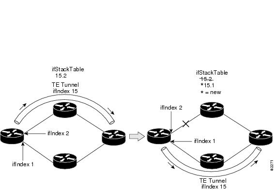
Because a TE tunnel is represented as an IF MIB ifTable entry, the ifStackTable also contains an entry corresponding to the TE tunnel. If the TE tunnel is successfully signaled, the ifStackTable also contains a link between the tunnel interface and one MPLS interface. Note that because it is possible for a TE tunnel to not have a corresponding signaled path, it is thus possible for a TE tunnel's ifStackTable entry to not have a corresponding lower layer. In this case, the lower layer variable contains the value of 0.
The figure below shows a TE tunnel before (left) and after (right) being rerouted and the effect on the ifStackTable. When ifIndex 2 fails, the TE tunnel is rerouted through ifIndex1, the 15.2 entry is removed from the ifStackTable, and the 15.1 entry is added.
MPLS Label Switching Router MIB Enhancements
All of the ifIndex references in the MPLS-LSR-MIB tables have changed from the ifIndex of the underlying physical or virtual interface to the ifIndex of the MPLS layer.
The table below shows the specific changes.
| Table 4 | MPLS-LSR-MIB ifIndex Objects Enhanced |
|
Table |
ifIndex |
|---|---|
|
MPLS interface configuration table (mplsInterfaceConfTable) |
mplsInterfaceConfIndex |
|
MPLS in-segment table (mplsInSegmentTable) |
mplsInSegmentIfIndex |
|
MPLS cross-connect table (mplsXCTable) |
mplsInSegmentIfIndex |
|
MPLS out-segment table (mplsOutSegmentTable) |
mplsOutSegmentIfIndex |
The following objects from the mplsInterfaceConfTable are affected:
Benefits of the MPLS Enhancements to Interfaces MIB
Improved Accounting Capability
By viewing the MPLS layer, you get MPLS-encapsulated traffic counters that do not include non-MPLS encapsulated traffic (for example, IP packets). Therefore, the counters are more useful for MPLS-related statistics.
How to Configure MPLS Enhancements to Interfaces MIB
Enabling the SNMP Agent
DETAILED STEPS
| Command or Action | Purpose | |
|---|---|---|
Step 1 |
enable
Example: Router> enable |
Enables privileged EXEC mode. |
Step 2 |
show running-config
Example: Router# show running-config |
Displays the running configuration of the router so that you can determine if an SNMP agent is already running on the device. If no SNMP information is displayed, continue with the next step. If any SNMP information is displayed, you can modify the information or change it as desired. |
Step 3 |
configure terminal
Example: Router# configure terminal |
Enters global configuration mode. |
Step 4 |
snmp-server community
string [view
view-name] [ro
number]
Example: Router(config)# snmp-server community public ro |
Configures read-only (ro) community strings for the MPLS Label Distribution Protocol (LDP) MIB. |
Step 5 |
end
Example: Router(config)# end |
Exits to privileged EXEC mode. |
Step 6 |
write memory
Example: Router# write memory |
Writes the modified SNMP configuration into NVRAM of the router, permanently saving the SNMP settings. |
Step 7 |
show running-config
Example: Router# show running-config |
Displays the running configuration of the router so that you can determine if an SNMP agent is already running on the device. If you see any snmp-server statements, SNMP has been enabled on the router. If any SNMP information is displayed, you can modify the information or change it as desired. |
Configuration Examples for the MPLS Enhancements to Interfaces MIB
MPLS Enhancements to Interfaces MIB: Examples
The following example shows how to enable an SNMP agent:
Router# configure terminal
Router(config)# snmp-server community
In the following example, SNMPv1 and SNMPv2C are enabled. The configuration permits any SNMP manager to access all objects with read-only permissions using the community string public.
Router(config)# snmp-server community public
In the following example, read-only access is allowed for all objects to members of access list 4 that specify the comaccess community string. No other SNMP managers have access to any objects.
Router(config)# snmp-server community comaccess ro 4
Additional References
Related Documents
|
Related Topic |
Document Title |
|---|---|
|
SNMP commands |
Cisco IOS Network Management Command Reference |
|
SNMP configuration |
"Configuring SNMP Support" in the Network Management Configuration Guide. |
|
A description of SNMP agent support for the MPLS Traffic Engineering MIB (MPLS TE MIB) |
MPLS Traffic Engineering (TE) MIB |
MIBs
RFCs
|
RFCs |
Title |
|---|---|
|
RFC 1156 |
Management Information Base for Network Management of TCP/IP-based internets |
|
RFC 1157 |
A Simple Network Management Protocol (SNMP) |
|
RFC 1213 |
Management Information Base for Network Management of TCP/IP-based internets: MIB-II |
|
RFC 1229 |
Extensions to the Generic-Interface MIB |
|
RFC 2233 |
Interfaces MIB |
Technical Assistance
|
Description |
Link |
|---|---|
|
The Cisco Support website provides extensive online resources, including documentation and tools for troubleshooting and resolving technical issues with Cisco products and technologies. To receive security and technical information about your products, you can subscribe to various services, such as the Product Alert Tool (accessed from Field Notices), the Cisco Technical Services Newsletter, and Really Simple Syndication (RSS) Feeds. Access to most tools on the Cisco Support website requires a Cisco.com user ID and password. |
Feature Information for MPLS Enhancements to Interfaces MIB
The following table provides release information about the feature or features described in this module. This table lists only the software release that introduced support for a given feature in a given software release train. Unless noted otherwise, subsequent releases of that software release train also support that feature.
Use Cisco Feature Navigator to find information about platform support and Cisco software image support. To access Cisco Feature Navigator, go to www.cisco.com/go/cfn. An account on Cisco.com is not required.
| Table 5 | Feature Information for MPLS Enhancements to Interfaces MIB |
|
Feature Name |
Releases |
Feature Information |
|---|---|---|
|
MPLS Enhancements to Interfaces MIB |
12.0(23)S 12.3(8)T 12.2(33)SRA 12.2(33)SXH 12.2(33)SB Cisco IOS XE Release 2.1 |
This document describes the Multiprotocol Label Switching (MPLS) enhancements to the existing Interfaces MIB (RFC 2233) to support an MPLS layer. This layer provides counters and statistics specifically for MPLS. In Cisco IOS Release 12.0(23)S, this feature was introduced. This feature was integrated into Cisco IOS Release 12.3(8)T. This feature was integrated into Cisco IOS Release 12.2(33)SRA. This feature was integrated into Cisco IOS Release 12.2(33)SXH. This feature was integrated into Cisco IOS Release 12.2(33)SB. In Cisco IOS XE Release 2.1, this feature was implemented on the Cisco ASR 1000 Series Aggregation Services Routers. The following command was introduced or modified: snmp-server community. |
Glossary
ATM -- Asynchronous Transfer Mode. The international standard for cell relay in which multiple service types (such as voice, video, or data) are conveyed in fixed-length (53-byte) cells. Fixed-length cells allow cell processing to occur in hardware, thereby reducing transit delays. ATM is designed to take advantage of high-speed transmission media, such as E3, SONET, and T3.
ATM-AAL5 --ATM adaptation layer 5. One of four AALs recommended by the ITU-T. AAL5 supports connection-oriented variable bit rate (VBR) services and is used predominantly for the transfer of classical IP over ATM and LAN emulation (LANE) traffic. AAL5 uses simple and efficient AAL (SEAL) and is the least complex of the current AAL recommendations. It offers low bandwidth overhead and simpler processing requirements in exchange for reduced bandwidth capacity and error-recovery capability.
encapsulation -- Wrapping of data in a particular protocol header. For example, Ethernet data is wrapped in a specific Ethernet header before network transit. Also, when bridging dissimilar networks, the entire frame from one network is simply placed in the header used by the data link layer protocol of the other network.
IETF --Internet Engineering Task Force. A task force (consisting of more than 80 working groups) that is developing standards for the Internet and the IP suite of protocols.
interface --The boundary between adjacent layers of the ISO model.
label --A short, fixed-length identifier that is used to determine the forwarding of a packet.
label switching--A term used to describe the forwarding of IP (or other network layer) packets using a label swapping algorithm based on network layer routing algorithms. The forwarding of these packets uses the exact match algorithm and rewrites the label.
LSR --label switching router. A device that forwards Multiprotocol Label Switching (MPLS) packets based on the value of a fixed-length label encapsulated in each packet.
MIB --Management Information Base. A database of network management information that is used and maintained by a network management protocol such as Simple Network Management Protocol (SNMP). The value of a MIB object can be changed or retrieved by means of SNMP commands, usually through a network management system. MIB objects are organized in a tree structure that includes public (standard) and private (proprietary) branches.
MPLS --Multiprotocol Label Switching. A method for forwarding packets (frames) through a network. It enables routers at the edge of a network to apply labels to packets (frames). ATM switches or existing routers in the network core can switch packets according to the labels with minimal lookup overhead.
MPLS interface--An interface on which Multiprotocol Label Switching (MPLS) traffic is enabled.
MTU --maximum transmission unit. Maximum packet size, in bytes, that a particular interface can handle.
NMS --network management system. System responsible for managing at least part of a network. An NMS is generally a reasonably powerful and well-equipped computer, such as an engineering workstation. NMSs communicate with agents to help keep track of network statistics and resources.
OID --object identifier. Values are defined in specific MIB modules. The Event MIB allows you or an NMS to watch over specified objects and to set event triggers based on existence, threshold, and Boolean tests. An event occurs when a trigger is fired; this means that a specified test on an object returns a value of true. To create a trigger, you or a network management system (NMS) configures a trigger entry in the mteTriggerTable of the Event MIB. This trigger entry specifies the OID of the object to be watched. For each trigger entry type, corresponding tables (existence, threshold, and Boolean tables) are populated with the information required for carrying out the test. The MIB can be configured so that when triggers are activated (fired) either a Simple Network Management Protocol (SNMP) Set is performed, a notification is sent out to the interested host, or both.
SNMP --Simple Network Management Protocol. A management protocol used almost exclusively in TCP/IP networks. SNMP provides a means for monitoring and controlling network devices, and for managing configurations, statistics collection, performance, and security.
traffic engineering tunnel--A label-switched tunnel that is used for traffic engineering. Such a tunnel is set up through means other than normal Layer 3 routing; it is used to direct traffic over a path different from the one that Layer 3 routing could cause the tunnel to take.
trap --A message sent by a Simple Network Management Protocol (SNMP) agent to a network management station, console, or terminal, indicating that a significant event occurred. Traps are less reliable than notification requests, because the receiver does not send an acknowledgment when it receives a trap. The sender cannot determine if the trap was received.
tunnel --A secure communication path between two peers, such as routers.
Cisco and the Cisco logo are trademarks or registered trademarks of Cisco and/or its affiliates in the U.S. and other countries. To view a list of Cisco trademarks, go to this URL: www.cisco.com/go/trademarks. Third-party trademarks mentioned are the property of their respective owners. The use of the word partner does not imply a partnership relationship between Cisco and any other company. (1110R)
Any Internet Protocol (IP) addresses and phone numbers used in this document are not intended to be actual addresses and phone numbers. Any examples, command display output, network topology diagrams, and other figures included in the document are shown for illustrative purposes only. Any use of actual IP addresses or phone numbers in illustrative content is unintentional and coincidental.