
 Feedback
Contents
ICMP for IPv6
ICMP in IPv6 functions the same as ICMP in IPv4. ICMP for IPv6 generates error messages, such as ICMP destination unreachable messages, and informational messages, such as ICMP echo request and reply messages.
Finding Feature Information
Your software release may not support all the features documented in this module. For the latest caveats and feature information, see Bug Search Tool and the release notes for your platform and software release. To find information about the features documented in this module, and to see a list of the releases in which each feature is supported, see the feature information table at the end of this module.
Use Cisco Feature Navigator to find information about platform support and Cisco software image support. To access Cisco Feature Navigator, go to www.cisco.com/go/cfn. An account on Cisco.com is not required.
Information About ICMP for IPv6
ICMP for IPv6
Internet Control Message Protocol (ICMP) in IPv6 functions the same as ICMP in IPv4. ICMP generates error messages, such as ICMP destination unreachable messages, and informational messages, such as ICMP echo request and reply messages. Additionally, ICMP packets in IPv6 are used in the IPv6 neighbor discovery process, path MTU discovery, and the Multicast Listener Discovery (MLD) protocol for IPv6. MLD is used by IPv6 devices to discover multicast listeners (nodes that want to receive multicast packets destined for specific multicast addresses) on directly attached links. MLD is based on version 2 of the Internet Group Management Protocol (IGMP) for IPv4.
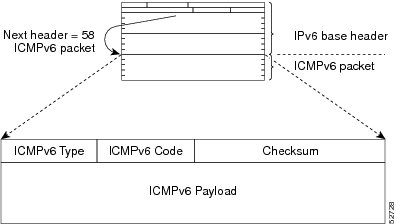
A value of 58 in the Next Header field of the basic IPv6 packet header identifies an IPv6 ICMP packet. ICMP packets in IPv6 are like a transport-layer packet in the sense that the ICMP packet follows all the extension headers and is the last piece of information in the IPv6 packet. Within IPv6 ICMP packets, the ICMPv6 Type and ICMPv6 Code fields identify IPv6 ICMP packet specifics, such as the ICMP message type. The value in the Checksum field is derived (computed by the sender and checked by the receiver) from the fields in the IPv6 ICMP packet and the IPv6 pseudoheader. The ICMPv6 Data field contains error or diagnostic information relevant to IP packet processing. The figure below shows the IPv6 ICMP packet header format.
IPv6 Neighbor Solicitation Message
A value of 135 in the Type field of the ICMP packet header identifies a neighbor solicitation message. Neighbor solicitation messages are sent on the local link when a node wants to determine the link-layer address of another node on the same local link (see the figure below). When a node wants to determine the link-layer address of another node, the source address in a neighbor solicitation message is the IPv6 address of the node sending the neighbor solicitation message. The destination address in the neighbor solicitation message is the solicited-node multicast address that corresponds to the IPv6 address of the destination node. The neighbor solicitation message also includes the link-layer address of the source node.
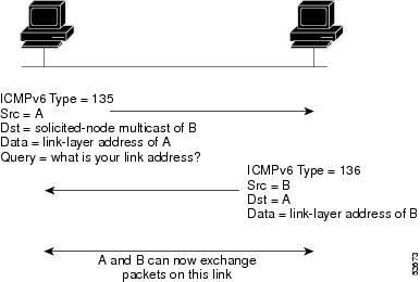
After receiving the neighbor solicitation message, the destination node replies by sending a neighbor advertisement message, which has a value of 136 in the Type field of the ICMP packet header, on the local link. The source address in the neighbor advertisement message is the IPv6 address of the node (more specifically, the IPv6 address of the node interface) sending the neighbor advertisement message. The destination address in the neighbor advertisement message is the IPv6 address of the node that sent the neighbor solicitation message. The data portion of the neighbor advertisement message includes the link-layer address of the node sending the neighbor advertisement message.
After the source node receives the neighbor advertisement, the source node and destination node can communicate.
Neighbor solicitation messages are also used to verify the reachability of a neighbor after the link-layer address of a neighbor is identified. When a node wants to verify the reachability of a neighbor, the destination address in a neighbor solicitation message is the unicast address of the neighbor.
Neighbor advertisement messages are also sent when there is a change in the link-layer address of a node on a local link. When there is such a change, the destination address for the neighbor advertisement is the all-nodes multicast address.
Neighbor solicitation messages are also used to verify the reachability of a neighbor after the link-layer address of a neighbor is identified. Neighbor unreachability detection identifies the failure of a neighbor or the failure of the forward path to the neighbor, and is used for all paths between hosts and neighboring nodes (hosts or devices). Neighbor unreachability detection is performed for neighbors to which only unicast packets are being sent and is not performed for neighbors to which multicast packets are being sent.
A neighbor is considered reachable when a positive acknowledgment is returned from the neighbor (indicating that packets previously sent to the neighbor have been received and processed). A positive acknowledgment from an upper-layer protocol (such as TCP) indicates that a connection is making forward progress (reaching its destination) or the receipt of a neighbor advertisement message in response to a neighbor solicitation message. If packets are reaching the peer, they are also reaching the next-hop neighbor of the source. Therefore, forward progress is also a confirmation that the next-hop neighbor is reachable.
For destinations that are not on the local link, forward progress implies that the first-hop device is reachable. When acknowledgments from an upper-layer protocol are not available, a node probes the neighbor using unicast neighbor solicitation messages to verify that the forward path is still working.
The return of a solicited neighbor advertisement message from the neighbor is a positive acknowledgment that the forward path is still working (neighbor advertisement messages that have the solicited flag set to a value of 1 are sent only in response to a neighbor solicitation message). Unsolicited messages confirm only the one-way path from the source to the destination node; solicited neighbor advertisement messages indicate that a path is working in both directions.
 Note | A neighbor advertisement message that has the solicited flag set to a value of 0 must not be considered as a positive acknowledgment that the forward path is still working. |
Neighbor solicitation messages are also used in the stateless autoconfiguration process to verify the uniqueness of unicast IPv6 addresses before the addresses are assigned to an interface. Duplicate address detection is performed first on a new, link-local IPv6 address before the address is assigned to an interface (the new address remains in a tentative state while duplicate address detection is performed). Specifically, a node sends a neighbor solicitation message with an unspecified source address and a tentative link-local address in the body of the message. If another node is already using that address, the node returns a neighbor advertisement message that contains the tentative link-local address. If another node is simultaneously verifying the uniqueness of the same address, that node also returns a neighbor solicitation message. If no neighbor advertisement messages are received in response to the neighbor solicitation message and no neighbor solicitation messages are received from other nodes that are attempting to verify the same tentative address, the node that sent the original neighbor solicitation message considers the tentative link-local address to be unique and assigns the address to the interface.
Every IPv6 unicast address (global or link-local) must be verified for uniqueness on the link; however, until the uniqueness of the link-local address is verified, duplicate address detection is not performed on any other IPv6 addresses associated with the link-local address. The Cisco implementation of duplicate address detection in the Cisco software does not verify the uniqueness of anycast or global addresses that are generated from 64-bit interface identifiers.
IPv6 Router Advertisement Message
Router advertisement (RA) messages, which have a value of 134 in the Type field of the ICMP packet header, are periodically sent out each configured interface of an IPv6 device. For stateless autoconfiguration to work properly, the advertised prefix length in RA messages must always be 64 bits.
The RA messages are sent to the all-nodes multicast address (see the figure below).
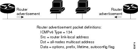
RA messages typically include the following information:
- One or more onlink IPv6 prefixes that nodes on the local link can use to automatically configure their IPv6 addresses
- Lifetime information for each prefix included in the advertisement
- Sets of flags that indicate the type of autoconfiguration (stateless or stateful) that can be completed
- Default device information (whether the device sending the advertisement should be used as a default device and, if so, the amount of time, in seconds, the device should be used as a default device)
- Additional information for hosts, such as the hop limit and maximum transmission unit (MTU) a host should use in packets that it originates
RAs are also sent in response to device solicitation messages. Device solicitation messages, which have a value of 133 in the Type field of the ICMP packet header, are sent by hosts at system startup so that the host can immediately autoconfigure without needing to wait for the next scheduled RA message. Given that device solicitation messages are usually sent by hosts at system startup (the host does not have a configured unicast address), the source address in device solicitation messages is usually the unspecified IPv6 address (0:0:0:0:0:0:0:0). If the host has a configured unicast address, the unicast address of the interface sending the device solicitation message is used as the source address in the message. The destination address in device solicitation messages is the all-devices multicast address with a scope of the link. When an RA is sent in response to a device solicitation, the destination address in the RA message is the unicast address of the source of the device solicitation message.
The following RA message parameters can be configured:
- The time interval between periodic RA messages
- The "device lifetime" value, which indicates the usefulness of a device as the default device (for use by all nodes on a given link)
- The network prefixes in use on a given link
- The time interval between neighbor solicitation message retransmissions (on a given link)
- The amount of time a node considers a neighbor reachable (for use by all nodes on a given link)
The configured parameters are specific to an interface. The sending of RA messages (with default values) is automatically enabled on Ethernet and FDDI interfaces when the ipv6 unicast-routing command is configured. For other interface types, the sending of RA messages must be manually configured by using the no ipv6 nd ra suppress command. The sending of RA messages can be disabled on individual interfaces by using the ipv6 nd ra suppress command.
Default Router Preferences for Traffic Engineering
Hosts discover and select default devices by listening to Router Advertisements (RAs). Typical default device selection mechanisms are suboptimal in certain cases, such as when traffic engineering is needed. For example, two devices on a link may provide equivalent but not equal-cost routing, and policy may dictate that one of the devices is preferred. Some examples are as follows:
- Multiple devices that route to distinct sets of prefixes--Redirects (sent by nonoptimal devices for a destination) mean that hosts can choose any device and the system will work. However, traffic patterns may mean that choosing one of the devices would lead to considerably fewer redirects.
- Accidentally deploying a new device--Deploying a new device before it has been fully configured could lead to hosts adopting the new device as a default device and traffic disappearing. Network managers may want to indicate that some devices are more preferred than others.
- Multihomed situations--Multihomed situations may become more common, because of multiple physical links and because of the use of tunneling for IPv6 transport. Some of the devices may not provide full default routing because they route only to the 6-to-4 prefix or they route only to a corporate intranet. These situations cannot be resolved with redirects, which operate only over a single link.
The default router preference (DRP) feature provides a basic preference metric (low, medium, or high) for default devices. The DRP of a default device is signaled in unused bits in RA messages. This extension is backward compatible, both for devices (setting the DRP bits) and hosts (interpreting the DRP bits). These bits are ignored by hosts that do not implement the DRP extension. Similarly, the values sent by devices that do not implement the DRP extension will be interpreted by hosts that do implement it as indicating a "medium" preference. DRPs need to be configured manually.
Additional References
Related Documents
| Related Topic | Document Title |
|---|---|
|
IPv6 addressing and connectivity |
IPv6 Configuration Guide |
|
Cisco IOS commands |
|
|
IPv6 commands |
Cisco IOS IPv6 Command Reference |
|
Cisco IOS IPv6 features |
Cisco IOS IPv6 Feature Mapping |
MIBs
Technical Assistance
| Description | Link |
|---|---|
|
The Cisco Support and Documentation website provides online resources to download documentation, software, and tools. Use these resources to install and configure the software and to troubleshoot and resolve technical issues with Cisco products and technologies. Access to most tools on the Cisco Support and Documentation website requires a Cisco.com user ID and password. |
Feature Information for ICMP for IPv6
The following table provides release information about the feature or features described in this module. This table lists only the software release that introduced support for a given feature in a given software release train. Unless noted otherwise, subsequent releases of that software release train also support that feature.
Use Cisco Feature Navigator to find information about platform support and Cisco software image support. To access Cisco Feature Navigator, go to www.cisco.com/go/cfn. An account on Cisco.com is not required.
| Table 1 | Feature Information for ICMP for IPv6 |
| Feature Name | Releases | Feature Information |
|---|---|---|
|
IPv6: ICMPv6 |
12.0(22)S 12.2(2)T 12.2(14)S 12.2(17a)SX1 12.2(25)SG 12.2(28)SB 12.2(33)SRA 12.2(2)T Cisco IOS XE Release 2.1 |
ICMP in IPv6 functions similarly to ICMP in IPv4. ICMP generates error messages, such as ICMP destination unreachable messages, and informational messages, such as ICMP echo request and reply messages. No commands were introduced or modified. |
Cisco and the Cisco logo are trademarks or registered trademarks of Cisco and/or its affiliates in the U.S. and other countries. To view a list of Cisco trademarks, go to this URL: www.cisco.com/go/trademarks. Third-party trademarks mentioned are the property of their respective owners. The use of the word partner does not imply a partnership relationship between Cisco and any other company. (1110R)
Any Internet Protocol (IP) addresses and phone numbers used in this document are not intended to be actual addresses and phone numbers. Any examples, command display output, network topology diagrams, and other figures included in the document are shown for illustrative purposes only. Any use of actual IP addresses or phone numbers in illustrative content is unintentional and coincidental.