
 Feedback
Contents
- Implementing IPv6 Addressing and Basic Connectivity
- Finding Feature Information
- Prerequisites for Implementing IPv6 Addressing and Basic Connectivity
- Restrictions for Implementing IPv6 Addressing and Basic Connectivity
- Information About Implementing IPv6 Addressing and Basic Connectivity
- IPv6 for Cisco IOS Software
- Large IPv6 Address Space for Unique Addresses
- IPv6 Address Formats
- IPv6 Address Type Unicast
- Aggregatable Global Address
- Link-Local Address
- IPv4-Compatible IPv6 Address
- Unique Local Address
- Site-Local Address
- IPv6 Address Type Anycast
- IPv6 Address Type Multicast
- IPv6 Multicast Groups
- IPv6 Address Output Display
- Simplified IPv6 Packet Header
- Cisco Express Forwarding and Distributed Cisco Express Forwarding Switching for IPv6
- Unicast Reverse Path Forwarding
- DNS for IPv6
- Path MTU Discovery for IPv6
- Cisco Discovery Protocol IPv6 Address Support
- ICMP for IPv6
- IPv6 ICMP Rate Limiting
- IPv6 Neighbor Discovery
- Stateful Switchover
- IPv6 Neighbor Solicitation Message
- Enhanced IPv6 Neighbor Discovery Cache Management
- IPv6 Router Advertisement Message
- Default Router Preferences for Traffic Engineering
- IPv6 Neighbor Redirect Message
- Per-Interface Neighbor Discovery Cache Limit
- Link, Subnet, and Site Addressing Changes
- IPv6 Stateless Autoconfiguration
- Simplified Network Renumbering for IPv6 Hosts
- IPv6 General Prefixes
- DHCP for IPv6 Prefix Delegation
- IPv6 Prefix Aggregation
- IPv6 Site Multihoming
- IPv6 Data Links
- IPv6 for Cisco IOS Software Support for Wide-Area Networking Technologies
- IPv6 Addresses and PVCs
- Routed Bridge Encapsulation for IPv6
- IPv6 Redirect Messages
- IPv6 on BVI Interfaces for Bridging and Routing
- Dual IPv4 and IPv6 Protocol Stacks
- How to Implement IPv6 Addressing and Basic Connectivity
- Configuring IPv6 Addressing and Enabling IPv6 Routing
- Configuring a Neighbor Discovery Cache Limit
- Configuring a Neighbor Discovery Cache Limit on a Specified Router Interface
- Configuring a Neighbor Discovery Cache Limit on All Router Interfaces
- Tuning the Parameters for IPv6 Neighbor Discovery
- Defining and Using IPv6 General Prefixes
- Defining a General Prefix Manually
- Defining a General Prefix Based on a 6to4 Interface
- Defining a General Prefix with the DHCP for IPv6 Prefix Delegation Client Function
- Using a General Prefix in IPv6
- Configuring an Interface to Support the IPv4 and IPv6 Protocol Stacks
- Customizing IPv6 ICMP Rate Limiting
- Configuring the DRP Extension for Traffic Engineering
- Configuring Cisco Express Forwarding and Distributed Cisco Express Forwarding Switching for IPv6
- Configuring Cisco Express Forwarding Switching on Distributed and Nondistributed Architecture Platforms
- Configuring Unicast RPF
- Mapping Hostnames to IPv6 Addresses
- Mapping IPv6 Addresses to IPv6 ATM and Frame Relay Interfaces
- Displaying IPv6 Redirect Messages
- Examples
- Configuration Examples for Implementing IPv6 Addressing and Basic Connectivity
- Example: IPv6 Addressing and IPv6 Routing Configuration
- Example: Tuning the Parameters for IPv6 Neighbor Discovery
- Example: Dual Protocol Stacks Configuration
- Example: IPv6 ICMP Rate Limiting Configuration
- Example: Cisco Express Forwarding and Distributed Cisco Express Forwarding Configuration
- Example: Hostname-to-Address Mappings Configuration
- Examples: IPv6 Address to ATM and Frame Relay PVC Mapping Configuration
- Example: IPv6 ATM PVC Mapping Configuration (Point-to-Point Interface)
- Example: IPv6 ATM PVC Mapping Configuration (Point-to-Multipoint Interface)
- Example: IPv6 Frame Relay PVC Mapping Configuration (Point-to-Point Interface)
- Example: IPv6 Frame Relay PVC Mapping Configuration (Point-to-Multipoint Interface)
- Additional References
- Feature Information for Implementing IPv6 Addressing and Basic Connectivity
Implementing IPv6 Addressing and Basic Connectivity
Implementing basic IPv6 connectivity in the Cisco IOS software consists of assigning IPv6 addresses to individual router interfaces. The forwarding of IPv6 traffic can be enabled globally, and Cisco Express Forwarding switching for IPv6 can also be enabled. Basic connectivity can be enhanced by configuring support for AAAA record types in the Domain Name System (DNS) name-to-address and address-to-name lookup processes, and by managing IPv6 neighbor discovery.
- Finding Feature Information
- Prerequisites for Implementing IPv6 Addressing and Basic Connectivity
- Restrictions for Implementing IPv6 Addressing and Basic Connectivity
- Information About Implementing IPv6 Addressing and Basic Connectivity
- How to Implement IPv6 Addressing and Basic Connectivity
- Configuration Examples for Implementing IPv6 Addressing and Basic Connectivity
- Additional References
- Feature Information for Implementing IPv6 Addressing and Basic Connectivity
Finding Feature Information
Your software release may not support all the features documented in this module. For the latest caveats and feature information, see Bug Search Tool and the release notes for your platform and software release. To find information about the features documented in this module, and to see a list of the releases in which each feature is supported, see the feature information table at the end of this module.
Use Cisco Feature Navigator to find information about platform support and Cisco software image support. To access Cisco Feature Navigator, go to www.cisco.com/go/cfn. An account on Cisco.com is not required.
Prerequisites for Implementing IPv6 Addressing and Basic Connectivity
- The following prerequisites apply to Cisco Express Forwarding and distributed Cisco Express Forwarding for IPv6:
- To forward IPv6 traffic using Cisco Express Forwarding or distributed Cisco Express Forwarding, you must configure forwarding of IPv6 unicast datagrams globally on the router by using the ipv6 unicast-routing command, and you must configure an IPv6 address on an interface by using the ipv6 address command.
- You must enable Cisco Express Forwarding for IPv4 globally on the router by using the ip cef command before enabling Cisco Express Forwarding for IPv6 globally on the router by using the ipv6 cef command.
- On distributed architecture platforms that support both Cisco Express Forwarding and distributed Cisco Express Forwarding, you must enable distributed Cisco Express Forwarding for IPv4 globally on the router by using the ip cef distributed command before enabling distributed Cisco Express Forwarding for IPv6 globally on the router by using the ipv6 cef distributed command.
- To use Unicast Reverse Path Forwarding (RPF), enable Cisco Express Forwarding switching or distributed Cisco Express Forwarding switching in the router. There is no need to configure the input interface for Cisco Express Forwarding switching. As long as Cisco Express Forwarding is running on the router, individual interfaces can be configured with other switching modes.

Note
For Unicast RPF to work, Cisco Express Forwarding must be configured globally in the router. Unicast RPF will not work without Cisco Express Forwarding.
Restrictions for Implementing IPv6 Addressing and Basic Connectivity
- In Cisco IOS Release 12.2(11)T or earlier releases, IPv6 supports only process switching for packet forwarding. Cisco Express Forwarding switching and distributed Cisco Express Forwarding switching for IPv6 are supported in Cisco IOS Release 12.2(13)T. Distributed Cisco Express Forwarding switching for IPv6 is supported in Cisco IOS Release 12.0(21)ST.
- IPv6 packets are transparent to Layer 2 LAN switches because the switches do not examine Layer 3 packet information before forwarding IPv6 frames. Therefore, IPv6 hosts can be directly attached to Layer 2 LAN switches.
- In any Cisco IOS release with IPv6 support, multiple IPv6 global addresses within the same prefix can be configured on an interface. However, multiple IPv6 link-local addresses on an interface are not supported. See the "Mapping IPv6 Addresses to IPv6 ATM and Frame Relay Interfaces" section for information on configuring multiple IPv6 global addresses within the same prefix on an interface.
- Because RFC 3879 deprecates the use of site-local addresses, configuration of private IPv6 addresses should be done following the recommendations of unique local addressing (ULA) in RFC 4193.
- Bridge-Group Virtual Interfaces (BVIs) in IPv6 are not supported with NAT-PT and wireless interfaces Dot11Radio.
Information About Implementing IPv6 Addressing and Basic Connectivity
- IPv6 for Cisco IOS Software
- Large IPv6 Address Space for Unique Addresses
- IPv6 Address Formats
- IPv6 Address Type Unicast
- IPv6 Address Type Anycast
- IPv6 Address Type Multicast
- IPv6 Address Output Display
- Simplified IPv6 Packet Header
- Cisco Express Forwarding and Distributed Cisco Express Forwarding Switching for IPv6
- DNS for IPv6
- Path MTU Discovery for IPv6
- Cisco Discovery Protocol IPv6 Address Support
- ICMP for IPv6
- IPv6 Neighbor Discovery
- Link, Subnet, and Site Addressing Changes
- IPv6 Prefix Aggregation
- IPv6 Site Multihoming
- IPv6 Data Links
- Routed Bridge Encapsulation for IPv6
- IPv6 Redirect Messages
- IPv6 on BVI Interfaces for Bridging and Routing
- Dual IPv4 and IPv6 Protocol Stacks
IPv6 for Cisco IOS Software
IPv6, formerly named IPng (next generation), is the latest version of the Internet Protocol (IP). IP is a packet-based protocol used to exchange data, voice, and video traffic over digital networks. IPv6 was proposed when it became clear that the 32-bit addressing scheme of IP version 4 (IPv4) was inadequate to meet the demands of Internet growth. IPv6 is based on IP but with a much larger address space and improvements such as a simplified main header and extension headers. IPv6 is described initially in RFC 2460, Internet Protocol, Version 6 (IPv6) Specification, issued by the Internet Engineering Task Force (IETF). Further RFCs describe the architecture and services supported by IPv6.
The architecture of IPv6 has been designed to allow existing IPv4 users to transition easily to IPv6 while providing services such as end-to-end security, quality of service (QoS), and globally unique addresses. The larger IPv6 address space allows networks to scale and provide global reachability. The simplified IPv6 packet header format handles packets more efficiently. IPv6 prefix aggregation, simplified network renumbering, and IPv6 site multihoming capabilities provide an IPv6 addressing hierarchy that allows for more efficient routing. IPv6 supports widely deployed routing protocols such as Routing Information Protocol (RIP), Integrated Intermediate System-to-Intermediate System (IS-IS), Open Shortest Path First (OSPF) for IPv6, and multiprotocol Border Gateway Protocol (BGP). Other available features include stateless autoconfiguration, enhanced support for Mobile IPv6, and an increased number of multicast addresses.
Large IPv6 Address Space for Unique Addresses
The primary motivation for IPv6 is the need to meet the demand for globally unique IP addresses. IPv6 quadruples the number of network address bits from 32 bits (in IPv4) to 128 bits, which provides more than enough globally unique IP addresses for every networked device on the planet. By being globally unique, IPv6 addresses inherently enable global reachability and end-to-end security for networked devices, functionality that is crucial to the applications and services that are driving the demand for the addresses. Additionally, the flexibility of the IPv6 address space reduces the need for private addresses; therefore, IPv6 enables new application protocols that do not require special processing by border routers at the edge of networks.
IPv6 Address Formats
IPv6 addresses are represented as a series of 16-bit hexadecimal fields separated by colons (:) in the format: x:x:x:x:x:x:x:x. Following are two examples of IPv6 addresses:
2001:DB8:7654:3210:FEDC:BA98:7654:3210
2001:DB8:0:0:8:800:200C:417A
It is common for IPv6 addresses to contain successive hexadecimal fields of zeros. To make IPv6 addresses less cumbersome, two colons (::) may be used to compress successive hexadecimal fields of zeros at the beginning, middle, or end of an IPv6 address (the colons represent successive hexadecimal fields of zeros). The table below lists compressed IPv6 address formats.
A double colon may be used as part of the ipv6-address argument when consecutive 16-bit values are denoted as zero. You can configure multiple IPv6 addresses per interfaces, but only one link-local address.
Note | Two colons (::) can be used only once in an IPv6 address to represent the longest successive hexadecimal fields of zeros. The hexadecimal letters in IPv6 addresses are not case-sensitive. |
| Table 1 | Compressed IPv6 Address Formats |
|
IPv6 Address Type |
Preferred Format |
Compressed Format |
|---|---|---|
|
Unicast |
2001:0:0:0:DB8:800:200C:417A |
2001::DB8:800:200C:417A |
|
Multicast |
FF01:0:0:0:0:0:0:101 |
FF01::101 |
|
Loopback |
0:0:0:0:0:0:0:1 |
::1 |
|
Unspecified |
0:0:0:0:0:0:0:0 |
:: |
The loopback address listed in the table above may be used by a node to send an IPv6 packet to itself. The loopback address in IPv6 functions the same as the loopback address in IPv4 (127.0.0.1).
The unspecified address listed in the table above indicates the absence of an IPv6 address. For example, a newly initialized node on an IPv6 network may use the unspecified address as the source address in its packets until it receives its IPv6 address.
Note | The IPv6 unspecified address cannot be assigned to an interface. The unspecified IPv6 addresses must not be used as destination addresses in IPv6 packets or the IPv6 routing header. |
An IPv6 address prefix, in the format ipv6-prefix/prefix-length, can be used to represent bit-wise contiguous blocks of the entire address space. The ipv6-prefix must be in the form documented in RFC 2373 where the address is specified in hexadecimal using 16-bit values between colons. The prefix length is a decimal value that indicates how many of the high-order contiguous bits of the address comprise the prefix (the network portion of the address). For example, 2001:DB8:8086:6502::/32 is a valid IPv6 prefix.
IPv6 Address Type Unicast
An IPv6 unicast address is an identifier for a single interface, on a single node. A packet that is sent to a unicast address is delivered to the interface identified by that address. The Cisco IOS software supports the IPv6 unicast address types described in the following sections:
Aggregatable Global Address
An aggregatable global address is an IPv6 address from the aggregatable global unicast prefix. The structure of aggregatable global unicast addresses enables strict aggregation of routing prefixes that limits the number of routing table entries in the global routing table. Aggregatable global addresses are used on links that are aggregated upward through organizations, and eventually to the Internet service providers (ISPs).
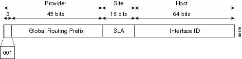
Aggregatable global IPv6 addresses are defined by a global routing prefix, a subnet ID, and an interface ID. Except for addresses that start with binary 000, all global unicast addresses have a 64-bit interface ID. The IPv6 global unicast address allocation uses the range of addresses that start with binary value 001 (2000::/3). The figure below shows the structure of an aggregatable global address.
Addresses with a prefix of 2000::/3 (001) through E000::/3 (111) are required to have 64-bit interface identifiers in the extended universal identifier (EUI)-64 format. The Internet Assigned Numbers Authority (IANA) allocates the IPv6 address space in the range of 2000::/16 to regional registries.
The aggregatable global address typically consists of a 48-bit global routing prefix and a 16-bit subnet ID or Site-Level Aggregator (SLA). In the IPv6 aggregatable global unicast address format document (RFC 2374), the global routing prefix included two other hierarchically structured fields named Top-Level Aggregator (TLA) and Next-Level Aggregator (NLA). The IETF decided to remove the TLS and NLA fields from the RFCs because these fields are policy-based. Some existing IPv6 networks deployed before the change might still be using networks based on the older architecture.
A 16-bit subnet field called the subnet ID could be used by individual organizations to create their own local addressing hierarchy and to identify subnets. A subnet ID is similar to a subnet in IPv4, except that an organization with an IPv6 subnet ID can support up to 65,535 individual subnets.
An interface ID is used to identify interfaces on a link. The interface ID must be unique to the link. It may also be unique over a broader scope. In many cases, an interface ID will be the same as or based on the link-layer address of an interface. Interface IDs used in aggregatable global unicast and other IPv6 address types must be 64 bits long and constructed in the modified EUI-64 format.
Interface IDs are constructed in the modified EUI-64 format in one of the following ways:
- For all IEEE 802 interface types (for example, Ethernet, and FDDI interfaces), the first three octets (24 bits) are taken from the Organizationally Unique Identifier (OUI) of the 48-bit link-layer address (the Media Access Control [MAC] address) of the interface, the fourth and fifth octets (16 bits) are a fixed hexadecimal value of FFFE, and the last three octets (24 bits) are taken from the last three octets of the MAC address. The construction of the interface ID is completed by setting the Universal/Local (U/L) bit--the seventh bit of the first octet--to a value of 0 or 1. A value of 0 indicates a locally administered identifier; a value of 1 indicates a globally unique IPv6 interface identifier.
- For other interface types (for example, serial, loopback, ATM, Frame Relay, and tunnel interface types--except tunnel interfaces used with IPv6 overlay tunnels), the interface ID is constructed in the same way as the interface ID for IEEE 802 interface types; however, the first MAC address from the pool of MAC addresses in the router is used to construct the identifier (because the interface does not have a MAC address).
- For tunnel interface types that are used with IPv6 overlay tunnels, the interface ID is the IPv4 address assigned to the tunnel interface with all zeros in the high-order 32 bits of the identifier.
If no IEEE 802 interface types are in the router, link-local IPv6 addresses are generated on the interfaces in the router in the following sequence:
- The router is queried for MAC addresses (from the pool of MAC addresses in the router).
- If no MAC addresses are available in the router, the serial number of the router is used to form the link-local addresses.
- If the serial number of the router cannot be used to form the link-local addresses, the router uses a message digest algorithm 5 (MD5) hash to determine the MAC address of the router from the hostname of the router.
Link-Local Address
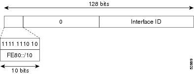
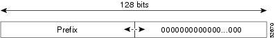
A link-local address is an IPv6 unicast address that can be automatically configured on any interface using the link-local prefix FE80::/10 (1111 1110 10) and the interface identifier in the modified EUI-64 format. Link-local addresses are used in the neighbor discovery protocol and the stateless autoconfiguration process. Nodes on a local link can use link-local addresses to communicate; the nodes do not need globally unique addresses to communicate. The figure below shows the structure of a link-local address.
IPv6 routers must not forward packets that have link-local source or destination addresses to other links.
IPv4-Compatible IPv6 Address
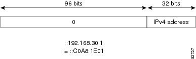
An IPv4-compatible IPv6 address is an IPv6 unicast address that has zeros in the high-order 96 bits of the address and an IPv4 address in the low-order 32 bits of the address. The format of an IPv4-compatible IPv6 address is 0:0:0:0:0:0:A.B.C.D or ::A.B.C.D. The entire 128-bit IPv4-compatible IPv6 address is used as the IPv6 address of a node and the IPv4 address embedded in the low-order 32 bits is used as the IPv4 address of the node. IPv4-compatible IPv6 addresses are assigned to nodes that support both the IPv4 and IPv6 protocol stacks and are used in automatic tunnels. The figure below shows the structure of an IPv4-compatible IPv6 address and a few acceptable formats for the address.
Unique Local Address
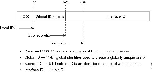
A unique local address is an IPv6 unicast address that is globally unique and is intended for local communications. They are not expected to be routable on the global Internet and are routable inside of a limited area, such as a site. They may also be routed between a limited set of sites.
A unique local address has the following characteristics:
- It has a globally unique prefix (that is, it has a high probability of uniqueness).
- It has a well-known prefix to allow for easy filtering at site boundaries.
- It allows sites to be combined or privately interconnected without creating any address conflicts or requiring renumbering of interfaces that use these prefixes.
- It is ISP-independent and can be used for communications inside of a site without having any permanent or intermittent Internet connectivity.
- If it is accidentally leaked outside of a site via routing or DNS, there is no conflict with any other addresses.
- Applications may treat unique local addresses like global scoped addresses.
The figure below shows the structure of a unique local address.
IPv6 Address Type Anycast
An anycast address is an address that is assigned to a set of interfaces that typically belong to different nodes. A packet sent to an anycast address is delivered to the closest interface--as defined by the routing protocols in use--identified by the anycast address. Anycast addresses are syntactically indistinguishable from unicast addresses because anycast addresses are allocated from the unicast address space. Assigning a unicast address to more than one interface makes a unicast address an anycast address. Nodes to which the anycast address is assigned must be explicitly configured to recognize that the address is an anycast address.
Note | Anycast addresses can be used only by a router, not a host, and anycast addresses must not be used as the source address of an IPv6 packet. |
The figure below shows the format of the subnet router anycast address; the address has a prefix concatenated by a series of zeros (the interface ID). The subnet router anycast address can be used to reach a router on the link that is identified by the prefix in the subnet router anycast address.
The following shows the configuration for an anycast prefix for 6to4 relay routers:
interface Tunnel0
no ip address
ipv6 address 2001:DB8:A00:1::1/32
ipv6 address 2001:DB8:c058:6301::/32 anycast
tunnel source Ethernet0
tunnel mode ipv6ip 6to4
!
interface Ethernet0
ip address 10.0.0.1 255.255.255.0
ip address 192.88.99.1 255.255.255.0 secondary
!
ipv6 route 2001:DB8::/32 Tunnel0
!
IPv6 Address Type Multicast
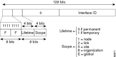
An IPv6 multicast address is an IPv6 address that has a prefix of FF00::/8 (1111 1111). An IPv6 multicast address is an identifier for a set of interfaces that typically belong to different nodes. A packet sent to a multicast address is delivered to all interfaces identified by the multicast address. The second octet following the prefix defines the lifetime and scope of the multicast address. A permanent multicast address has a lifetime parameter equal to 0; a temporary multicast address has a lifetime parameter equal to 1. A multicast address that has the scope of a node, link, site, or organization, or a global scope has a scope parameter of 1, 2, 5, 8, or E, respectively. For example, a multicast address with the prefix FF02::/16 is a permanent multicast address with a link scope. The figure below shows the format of the IPv6 multicast address.
IPv6 nodes (hosts and routers) are required to join (receive packets destined for) the following multicast groups:
- All-nodes multicast group FF02:0:0:0:0:0:0:1 (scope is link-local)
- Solicited-node multicast group FF02:0:0:0:0:1:FF00:0000/104 for each of its assigned unicast and anycast addresses
IPv6 routers must also join the all-routers multicast group FF02:0:0:0:0:0:0:2 (scope is link-local).
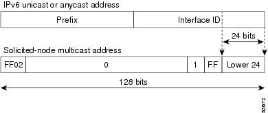
The solicited-node multicast address is a multicast group that corresponds to an IPv6 unicast or anycast address. IPv6 nodes must join the associated solicited-node multicast group for every unicast and anycast address to which it is assigned. The IPv6 solicited-node multicast address has the prefix FF02:0:0:0:0:1:FF00:0000/104 concatenated with the 24 low-order bits of a corresponding IPv6 unicast or anycast address (see the figure below). For example, the solicited-node multicast address corresponding to the IPv6 address 2037::01:800:200E:8C6C is FF02::1:FF0E:8C6C. Solicited-node addresses are used in neighbor solicitation messages.
Note | There are no broadcast addresses in IPv6. IPv6 multicast addresses are used instead of broadcast addresses. |
IPv6 Multicast Groups
An IPv6 address must be configured on an interface before the interface can forward IPv6 traffic. Configuring a site-local or global IPv6 address on an interface automatically configures a link-local address and activates IPv6 for that interface. Additionally, the configured interface automatically joins the following required multicast groups for that link:
IPv6 Address Output Display
When IPv6 or IPv4 command output displays an IPv6 address, a long IPv6 address can overflow into neighboring fields, causing the output to be difficult to read. The output fields were designed to work with the longest possible IPv4 address, which has 15 characters; IPv6 addresses can be up to 39 characters long. The following scheme has been adopted in IPv4 and IPv6 commands to allow the appropriate length of IPv6 address to be displayed and move the following fields to the next line, if necessary. The fields that are moved are kept in alignment with the header row.
Using the output display from the where command as an example, eight connections are displayed. The first six connections feature IPv6 addresses; the last two connections feature IPv4 addresses.
Router# where
Conn Host                Address             Byte  Idle Conn Name
   1 test5               2001:DB8:3333:4::5    6    24 test5
   2 test4               2001:DB8:3333:44::5
                                                6    24 test4
   3 2001:DB8:3333:4::5 2001:DB8:3333:4::5    6    24 2001:DB8:3333:4::5
   4 2001:DB8:3333:44::5
                         2001:DB8:3333:44::5
                                                6    23 2001:DB8:3333:44::5
   5 2001:DB8:3000:4000:5000:6000:7000:8001
                         2001:DB8:3000:4000:5000:6000:7000:8001
                                                6    20 2001:DB8:3000:4000:5000:6000:
   6 2001:DB8:1::1      2001:DB8:1::1         0     1 2001:DB8:1::1
   7 10.1.9.1            10.1.9.1               0     0 10.1.9.1
   8 10.222.111.222      10.222.111.222         0     0 10.222.111.222
Connection 1 contains an IPv6 address that uses the maximum address length in the address field. Connection 2 shows the IPv6 address overflowing the address field and the following fields moved to the next line, but in alignment with the appropriate headers. Connection 3 contains an IPv6 address that fills the maximum length of the hostname and address fields without wrapping any lines. Connection 4 shows the effect of both the hostname and address fields containing a long IPv6 address. The output is shown over three lines keeping the correct heading alignment. Connection 5 displays a similar effect as connection 4 with a very long IPv6 address in the hostname and address fields. Note that the connection name field is actually truncated. Connection 6 displays a very short IPv6 address that does not require any change in the display. Connections 7 and 8 display short and long IPv4 addresses.
Note | The IPv6 address output display applies to all commands that display IPv6 addresses. |
Simplified IPv6 Packet Header
The basic IPv4 packet header has 12 fields with a total size of 20 octets (160 bits) (see the figure below). The 12 fields may be followed by an Options field, which is followed by a data portion that is usually the transport-layer packet. The variable length of the Options field adds to the total size of the IPv4 packet header. The shaded fields of the IPv4 packet header shown in the figure below are not included in the IPv6 packet header.
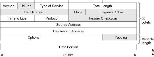
The basic IPv6 packet header has 8 fields with a total size of 40 octets (320 bits) (see the figure below). Fields were removed from the IPv6 header because, in IPv6, fragmentation is not handled by routers and checksums at the network layer are not used. Instead, fragmentation in IPv6 is handled by the source of a packet and checksums at the data link layer and transport layer are used. (In IPv4, the User Datagram Protocol (UDP) transport layer uses an optional checksum. In IPv6, use of the UDP checksum is required to check the integrity of the inner packet.) Additionally, the basic IPv6 packet header and Options field are aligned to 64 bits, which can facilitate the processing of IPv6 packets.
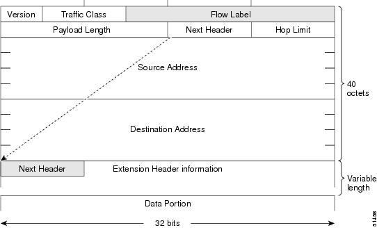
The table below lists the fields in the basic IPv6 packet header.
| Table 2 | Basic IPv6 Packet Header Fields |
|
Field |
Description |
|---|---|
|
Version |
Similar to the Version field in the IPv4 packet header, except that the field lists number 6 for IPv6 instead of number 4 for IPv4. |
|
Traffic Class |
Similar to the Type of Service field in the IPv4 packet header. The Traffic Class field tags packets with a traffic class that is used in differentiated services. |
|
Flow Label |
A new field in the IPv6 packet header. The Flow Label field tags packets with a specific flow that differentiates the packets at the network layer. |
|
Payload Length |
Similar to the Total Length field in the IPv4 packet header. The Payload Length field indicates the total length of the data portion of the packet. |
|
Next Header |
Similar to the Protocol field in the IPv4 packet header. The value of the Next Header field determines the type of information following the basic IPv6 header. The type of information following the basic IPv6 header can be a transport-layer packet, for example, a TCP or UDP packet, or an Extension Header, as shown in the figure immediately above. |
|
Hop Limit |
Similar to the Time to Live field in the IPv4 packet header. The value of the Hop Limit field specifies the maximum number of routers that an IPv6 packet can pass through before the packet is considered invalid. Each router decrements the value by one. Because no checksum is in the IPv6 header, the router can decrement the value without needing to recalculate the checksum, which saves processing resources. |
|
Source Address |
Similar to the Source Address field in the IPv4 packet header, except that the field contains a 128-bit source address for IPv6 instead of a 32-bit source address for IPv4. |
|
Destination Address |
Similar to the Destination Address field in the IPv4 packet header, except that the field contains a 128-bit destination address for IPv6 instead of a 32-bit destination address for IPv4. |
Following the eight fields of the basic IPv6 packet header are optional extension headers and the data portion of the packet. If present, each extension header is aligned to 64 bits. There is no fixed number of extension headers in an IPv6 packet. Together, the extension headers form a chain of headers. Each extension header is identified by the Next Header field of the previous header. Typically, the final extension header has a Next Header field of a transport-layer protocol, such as TCP or UDP. The figure below shows the IPv6 extension header format.
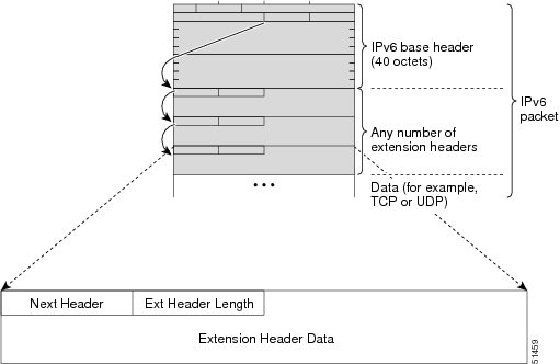
The table below lists the extension header types and their Next Header field values.
| Table 3 | IPv6 Extension Header Types |
|
Header Type |
Next Header Value |
Description |
|---|---|---|
|
Hop-by-hop options header |
0 |
This header is processed by all hops in the path of a packet. When present, the hop-by-hop options header always follows immediately after the basic IPv6 packet header. |
|
Destination options header |
60 |
The destination options header can follow any hop-by-hop options header, in which case the destination options header is processed at the final destination and also at each visited address specified by a routing header. Alternatively, the destination options header can follow any Encapsulating Security Payload (ESP) header, in which case the destination options header is processed only at the final destination. |
|
Routing header |
43 |
The routing header is used for source routing. |
|
Fragment header |
44 |
The fragment header is used when a source must fragment a packet that is larger than the maximum transmission unit (MTU) for the path between itself and a destination. The Fragment header is used in each fragmented packet. |
|
Authentication header and ESP header |
51 50 |
The Authentication header and the ESP header are used within IP Security Protocol (IPsec) to provide authentication, integrity, and confidentiality of a packet. These headers are identical for both IPv4 and IPv6. |
|
Upper-layer headers |
6 (TCP) 17 (UDP) |
The upper-layer (transport) headers are the typical headers used inside a packet to transport the data. The two main transport protocols are TCP and UDP. |
|
Mobility headers |
135 |
Extension headers used by mobile nodes, correspondent nodes, and home agents in all messaging related to the creation and management of bindings. |
Cisco Express Forwarding and Distributed Cisco Express Forwarding Switching for IPv6
Cisco Express Forwarding is advanced, Layer 3 IP switching technology for the forwarding of IPv6 packets. Distributed Cisco Express Forwarding performs the same functions as Cisco Express Forwarding but for distributed architecture platforms such as the GSRs and the Cisco 7500 series routers. Distributed Cisco Express Forwarding for IPv6 and Cisco Express Forwarding for IPv6 function the same and offer the same benefits as for distributed Cisco Express Forwarding for IPv4 and Cisco Express Forwarding for IPv4--network entries that are added, removed, or modified in the IPv6 Routing Information Base (RIB), as dictated by the routing protocols in use, are reflected in the Forwarding Information Bases (FIBs), and the IPv6 adjacency tables maintain Layer 2 next-hop addresses for all entries in each FIB.
In Cisco IOS Release 12.0(21)ST, distributed Cisco Express Forwarding included support for IPv6 addresses and prefixes. In Cisco IOS Release 12.0(22)S or later releases and Cisco IOS Release 12.2(13)T or later releases, distributed Cisco Express Forwarding and Cisco Express Forwarding were enhanced to include support for separate FIBs for IPv6 global and link-local addresses.
Each IPv6 router interface has an association to one IPv6 global FIB and one IPv6 link-local FIB (multiple interfaces can have an association to the same FIB). All IPv6 router interfaces that are attached to the same IPv6 link share the same IPv6 link-local FIB. IPv6 packets that have an IPv6 global destination address are processed by the IPv6 global FIB; however, packets that have an IPv6 global destination address and an IPv6 link-local source address are sent to the RP for process switching and scope-error handling. Packets that have a link-local source address are not forwarded off of the local link and are sent to the RP for process switching and scope-error handling.
Unicast Reverse Path Forwarding
Use the Unicast RPF feature to mitigate problems caused by malformed or forged (spoofed) IPv6 source addresses that pass through an IPv6 router. Malformed or forged source addresses can indicate denial-of-service (DoS) attacks based on source IPv6 address spoofing.
When Unicast RPF is enabled on an interface, the router examines all packets received on that interface. The router verifies that the source address appears in the routing table and matches the interface on which the packet was received. This "look backward" ability is available only when Cisco Express Forwarding is enabled on the router, because the lookup relies on the presence of the FIB. Cisco Express Forwarding generates the FIB as part of its operation.
Note | Unicast RPF is an input function and is applied only on the input interface of a router at the upstream end of a connection. |
The Unicast RPF feature verifies whether any packet received at a router interface arrives on one of the best return paths to the source of the packet. The feature performs a reverse lookup in the Cisco Express Forwarding table. If Unicast RPF does not find a reverse path for the packet, Unicast RPF can drop or forward the packet, depending on whether an access control list (ACL) is specified. If an ACL is specified, then when (and only when) a packet fails the Unicast RPF check, the ACL is checked to verify if the packet should be dropped (using a deny statement in the ACL) or forwarded (using a permit statement in the ACL). Whether a packet is dropped or forwarded, the packet is counted in the global IP traffic statistics for Unicast RPF drops and in the interface statistics for Unicast RPF.
If no ACL is specified, the router drops the forged or malformed packet immediately and no ACL logging occurs. The router and interface Unicast RPF counters are updated.
Unicast RPF events can be logged by specifying the logging option for the ACL entries. Log information can be used to gather information about the attack, such as source address and time.
DNS for IPv6
IPv6 supports DNS record types that are supported in the DNS name-to-address and address-to-name lookup processes. The DNS record types support IPv6 addresses. IPv6 also supports the reverse mapping of IPv6 addresses to DNS names.
A name server is used to track information associated with domain names. A name server can maintain a database of hostname-to-address mappings. Each name can map to one or more IPv4 addresses, IPv6 addresses, or both address types. In order to use this service to map domain names to IPv6 addresses, you must specify a name server and enable the DNS.
The Cisco IOS software maintains a cache of hostname-to-address mappings for use by the connect, telnet, and ping commands, related Telnet support operations, and many other commands that generate command output. This cache speeds the conversion of names to addresses.
Similar to IPv4, IPv6 uses a naming scheme that allows a network device to be identified by its location within a hierarchical name space that provides for domains. Domain names are joined with periods (.) as the delimiting characters. For example, Cisco is a commercial organization that is identified by a com domain name, so its domain name is cisco.com. A specific device in this domain, the FTP server, for example, is identified as ftp.cisco.com.
Note | IP6.ARPA support was added in Cisco IOS Release 12.3(11)T. IP6.ARPA is not supported in releases prior to Cisco IOS Release 12.3(11)T. |
The table below lists the IPv6 DNS record types.
| Table 4 | IPv6 DNS Record Types |
Path MTU Discovery for IPv6
As in IPv4, path MTU discovery in IPv6 allows a host to dynamically discover and adjust to differences in the MTU size of every link along a given data path. In IPv6, however, fragmentation is handled by the source of a packet when the path MTU of one link along a given data path is not large enough to accommodate the size of the packets. Having IPv6 hosts handle packet fragmentation saves IPv6 router processing resources and helps IPv6 networks run more efficiently.
Note | In IPv6, the minimum link MTU is 1280 octets. Cisco recommends using an MTU value of 1500 octets for IPv6 links. |
Cisco Discovery Protocol IPv6 Address Support
The Cisco Discovery Protocol IPv6 address support for neighbor information feature adds the ability to transfer IPv6 addressing information between two Cisco devices. Cisco Discovery Protocol support for IPv6 addresses provides IPv6 information to network management products and troubleshooting tools.
ICMP for IPv6
Internet Control Message Protocol (ICMP) in IPv6 functions the same as ICMP in IPv4. ICMP generates error messages, such as ICMP destination unreachable messages, and informational messages, such as ICMP echo request and reply messages. Additionally, ICMP packets in IPv6 are used in the IPv6 neighbor discovery process, path MTU discovery, and the Multicast Listener Discovery (MLD) protocol for IPv6. MLD is used by IPv6 routers to discover multicast listeners (nodes that want to receive multicast packets destined for specific multicast addresses) on directly attached links. MLD is based on version 2 of the Internet Group Management Protocol (IGMP) for IPv4.
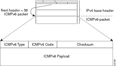
A value of 58 in the Next Header field of the basic IPv6 packet header identifies an IPv6 ICMP packet. ICMP packets in IPv6 are like a transport-layer packet in the sense that the ICMP packet follows all the extension headers and is the last piece of information in the IPv6 packet. Within IPv6 ICMP packets, the ICMPv6 Type and ICMPv6 Code fields identify IPv6 ICMP packet specifics, such as the ICMP message type. The value in the Checksum field is derived (computed by the sender and checked by the receiver) from the fields in the IPv6 ICMP packet and the IPv6 pseudoheader. The ICMPv6 Data field contains error or diagnostic information relevant to IP packet processing. The figure below shows the IPv6 ICMP packet header format.
IPv6 ICMP Rate Limiting
The IPv6 ICMP rate limiting feature implements a token bucket algorithm for limiting the rate at which IPv6 ICMP error messages are sent out on the network. The initial implementation of IPv6 ICMP rate limiting defined a fixed interval between error messages, but some applications such as traceroute often require replies to a group of requests sent in rapid succession. The fixed interval between error messages is not flexible enough to work with applications such as traceroute and can cause the application to fail.
Implementing a token bucket scheme allows a number of tokens--representing the ability to send one error message each--to be stored in a virtual bucket. The maximum number of tokens allowed in the bucket can be specified, and for every error message to be sent, one token is removed from the bucket. If a series of error messages is generated, error messages can be sent until the bucket is empty. When the bucket is empty of tokens, no IPv6 ICMP error messages are sent until a new token is placed in the bucket. The token bucket algorithm does not increase the average rate limiting time interval, and it is more flexible than the fixed time interval scheme.
IPv6 Neighbor Discovery
The IPv6 neighbor discovery process uses ICMP messages and solicited-node multicast addresses to determine the link-layer address of a neighbor on the same network (local link), verify the reachability of a neighbor, and track neighboring routers.
The IPv6 static cache entry for neighbor discovery feature allows static entries to be made in the IPv6 neighbor cache. Static routing requires an administrator to manually enter IPv6 addresses, subnet masks, gateways, and corresponding MAC addresses for each interface of each router into a table. Static routing enables more control but requires more work to maintain the table. The table must be updated each time routes are added or changed.
- Stateful Switchover
- IPv6 Neighbor Solicitation Message
- Enhanced IPv6 Neighbor Discovery Cache Management
- IPv6 Router Advertisement Message
- IPv6 Neighbor Redirect Message
- Per-Interface Neighbor Discovery Cache Limit
Stateful Switchover
IPv6 neighbor discovery supports stateful switchover (SSO) using Cisco Express Forwarding. When switchover occurs, the Cisco Express Forwarding adjacency state, which is checkpointed, is used to reconstruct the neighbor discovery cache.
IPv6 Neighbor Solicitation Message
A value of 135 in the Type field of the ICMP packet header identifies a neighbor solicitation message. Neighbor solicitation messages are sent on the local link when a node wants to determine the link-layer address of another node on the same local link (see the figure below). When a node wants to determine the link-layer address of another node, the source address in a neighbor solicitation message is the IPv6 address of the node sending the neighbor solicitation message. The destination address in the neighbor solicitation message is the solicited-node multicast address that corresponds to the IPv6 address of the destination node. The neighbor solicitation message also includes the link-layer address of the source node.
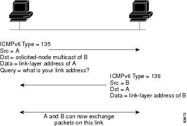
After receiving the neighbor solicitation message, the destination node replies by sending a neighbor advertisement message, which has a value of 136 in the Type field of the ICMP packet header, on the local link. The source address in the neighbor advertisement message is the IPv6 address of the node (more specifically, the IPv6 address of the node interface) sending the neighbor advertisement message. The destination address in the neighbor advertisement message is the IPv6 address of the node that sent the neighbor solicitation message. The data portion of the neighbor advertisement message includes the link-layer address of the node sending the neighbor advertisement message.
After the source node receives the neighbor advertisement, the source node and destination node can communicate.
Neighbor solicitation messages are also used to verify the reachability of a neighbor after the link-layer address of a neighbor is identified. When a node wants to verifying the reachability of a neighbor, the destination address in a neighbor solicitation message is the unicast address of the neighbor.
Neighbor advertisement messages are also sent when there is a change in the link-layer address of a node on a local link. When there is such a change, the destination address for the neighbor advertisement is the all-nodes multicast address.
Neighbor solicitation messages are also used to verify the reachability of a neighbor after the link-layer address of a neighbor is identified. Neighbor unreachability detection identifies the failure of a neighbor or the failure of the forward path to the neighbor, and is used for all paths between hosts and neighboring nodes (hosts or routers). Neighbor unreachability detection is performed for neighbors to which only unicast packets are being sent and is not performed for neighbors to which multicast packets are being sent.
A neighbor is considered reachable when a positive acknowledgment is returned from the neighbor (indicating that packets previously sent to the neighbor have been received and processed). A positive acknowledgment--from an upper-layer protocol (such as TCP)--indicates that a connection is making forward progress (reaching its destination) or the receipt of a neighbor advertisement message in response to a neighbor solicitation message. If packets are reaching the peer, they are also reaching the next-hop neighbor of the source. Therefore, forward progress is also a confirmation that the next-hop neighbor is reachable.
For destinations that are not on the local link, forward progress implies that the first-hop router is reachable. When acknowledgments from an upper-layer protocol are not available, a node probes the neighbor using unicast neighbor solicitation messages to verify that the forward path is still working.
The return of a solicited neighbor advertisement message from the neighbor is a positive acknowledgment that the forward path is still working (neighbor advertisement messages that have the solicited flag set to a value of 1 are sent only in response to a neighbor solicitation message). Unsolicited messages confirm only the one-way path from the source to the destination node; solicited neighbor advertisement messages indicate that a path is working in both directions.
Note | A neighbor advertisement message that has the solicited flag set to a value of 0 must not be considered as a positive acknowledgment that the forward path is still working. |
Neighbor solicitation messages are also used in the stateless autoconfiguration process to verify the uniqueness of unicast IPv6 addresses before the addresses are assigned to an interface. Duplicate address detection is performed first on a new, link-local IPv6 address before the address is assigned to an interface (the new address remains in a tentative state while duplicate address detection is performed). Specifically, a node sends a neighbor solicitation message with an unspecified source address and a tentative link-local address in the body of the message. If another node is already using that address, the node returns a neighbor advertisement message that contains the tentative link-local address. If another node is simultaneously verifying the uniqueness of the same address, that node also returns a neighbor solicitation message. If no neighbor advertisement messages are received in response to the neighbor solicitation message and no neighbor solicitation messages are received from other nodes that are attempting to verify the same tentative address, the node that sent the original neighbor solicitation message considers the tentative link-local address to be unique and assigns the address to the interface.
Every IPv6 unicast address (global or link-local) must be verified for uniqueness on the link; however, until the uniqueness of the link-local address is verified, duplicate address detection is not performed on any other IPv6 addresses associated with the link-local address. The Cisco implementation of duplicate address detection in the Cisco IOS software does not verify the uniqueness of anycast or global addresses that are generated from 64-bit interface identifiers.
Enhanced IPv6 Neighbor Discovery Cache Management
The enhanced IPv6 neighbor discovery cache management feature optimizes IPv6 neighbor discovery by providing ND cache autorefresh, unsolicited neighbor advertisement (NA) gleaning, and neighbor unreachability detection (NUD) exponential retransmit.
The neighbor discovery protocol enforces NUD, which can detect failing nodes or routers and changes to link-layer addresses. NUD is used to maintain reachability information for all paths between hosts and neighboring nodes, including host-to-host, host-to-router, and router-to-host communication.
The neighbor cache maintains mapping information about the IPv6 link-local or global address to the link-layer address. The neighbor cache also maintains the neighbor's reachability state, which is updated using NUD. Neighbors can be in one of the following five possible states:
- INCOMPLETE--Address resolution is in progress, and the link-layer address is not yet known.
- REACHABLE--Neighbor is known to be reachable within the last reachable time interval.
- STALE--Neighbor requires re-resolution, and traffic may flow to this neighbor.
- DELAY--Neighbor is pending re-resolution, and traffic might flow to this neighbor.
- PROBE--Neighbor re-resolution is in progress, and traffic might flow to this neighbor.
IPv6 Router Advertisement Message
Router advertisement (RA) messages, which have a value of 134 in the Type field of the ICMP packet header, are periodically sent out each configured interface of an IPv6 router. For stateless autoconfiguration to work properly, the advertised prefix length in RA messages must always be 64 bits.
The RA messages are sent to the all-nodes multicast address (see the figure below).
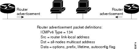
RA messages typically include the following information:
- One or more onlink IPv6 prefixes that nodes on the local link can use to automatically configure their IPv6 addresses
- Lifetime information for each prefix included in the advertisement
- Sets of flags that indicate the type of autoconfiguration (stateless or stateful) that can be completed
- Default router information (whether the router sending the advertisement should be used as a default router and, if so, the amount of time (in seconds) the router should be used as a default router)
- Additional information for hosts, such as the hop limit and MTU a host should use in packets that it originates
RAs are also sent in response to router solicitation messages. Router solicitation messages, which have a value of 133 in the Type field of the ICMP packet header, are sent by hosts at system startup so that the host can immediately autoconfigure without needing to wait for the next scheduled RA message. Given that router solicitation messages are usually sent by hosts at system startup (the host does not have a configured unicast address), the source address in router solicitation messages is usually the unspecified IPv6 address (0:0:0:0:0:0:0:0). If the host has a configured unicast address, the unicast address of the interface sending the router solicitation message is used as the source address in the message. The destination address in router solicitation messages is the all-routers multicast address with a scope of the link. When an RA is sent in response to a router solicitation, the destination address in the RA message is the unicast address of the source of the router solicitation message.
The following RA message parameters can be configured:
- The time interval between periodic RA messages
- The "router lifetime" value, which indicates the usefulness of a router as the default router (for use by all nodes on a given link)
- The network prefixes in use on a given link
- The time interval between neighbor solicitation message retransmissions (on a given link)
- The amount of time a node considers a neighbor reachable (for use by all nodes on a given link)
The configured parameters are specific to an interface. The sending of RA messages (with default values) is automatically enabled on Ethernet and FDDI interfaces when the ipv6 unicast-routing command is configured. For other interface types, the sending of RA messages must be manually configured by using the no ipv6 nd ra suppress command. The sending of RA messages can be disabled on individual interfaces by using the ipv6 nd ra suppress command.
Default Router Preferences for Traffic Engineering
Hosts discover and select default routers by listening to RAs. Typical default router selection mechanisms are suboptimal in certain cases, such as when traffic engineering is needed. For example, two routers on a link may provide equivalent but not equal-cost routing, and policy may dictate that one of the routers is preferred. Some examples are as follows:
- Multiple routers that route to distinct sets of prefixes--Redirects (sent by nonoptimal routers for a destination) mean that hosts can choose any router and the system will work. However, traffic patterns may mean that choosing one of the routers would lead to considerably fewer redirects.
- Accidentally deploying a new router--Deploying a new router before it has been fully configured could lead to hosts adopting the new router as a default router and traffic disappearing. Network managers may want to indicate that some routers are more preferred than others.
- Multihomed situations--Multihomed situations may become more common, because of multiple physical links and because of the use of tunneling for IPv6 transport. Some of the routers may not provide full default routing because they route only to the 6-to-4 prefix or they route only to a corporate intranet. These situations cannot be resolved with redirects, which operate only over a single link.
The default router preference (DRP) extension provides a coarse preference metric (low, medium, or high) for default routers. The DRP of a default router is signaled in unused bits in RA messages. This extension is backward compatible, both for routers (setting the DRP bits) and hosts (interpreting the DRP bits). These bits are ignored by hosts that do not implement the DRP extension. Similarly, the values sent by routers that do not implement the DRP extension will be interpreted by hosts that do implement it as indicating a "medium" preference.
DRPs need to be configured manually. For information on configuring the optional DRP extension, see the "Configuring the DRP Extension for Traffic Engineering" section.
IPv6 Neighbor Redirect Message
A value of 137 in the type field of the ICMP packet header identifies an IPv6 neighbor redirect message. Routers send neighbor redirect messages to inform hosts of better first-hop nodes on the path to a destination (see the figure below).
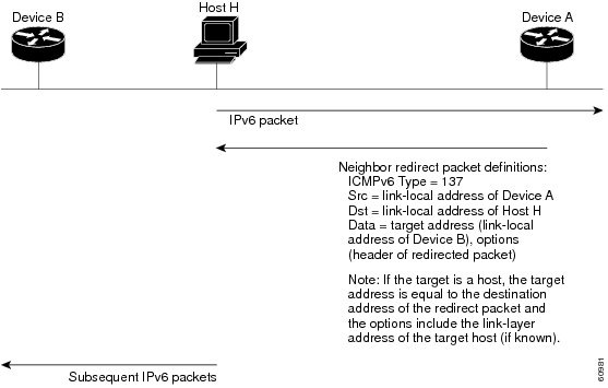
Note | A router must be able to determine the link-local address for each of its neighboring routers in order to ensure that the target address (the final destination) in a redirect message identifies the neighbor router by its link-local address. For static routing, the address of the next-hop router should be specified using the link-local address of the router; for dynamic routing, all IPv6 routing protocols must exchange the link-local addresses of neighboring routers. |
After forwarding a packet, a router should send a redirect message to the source of the packet under the following circumstances:
- The destination address of the packet is not a multicast address.
- The packet was not addressed to the router.
- The packet is about to be sent out the interface on which it was received.
- The router determines that a better first-hop node for the packet resides on the same link as the source of the packet.
- The source address of the packet is a global IPv6 address of a neighbor on the same link, or a link-local address.
Use the ipv6 icmp error-interval command to limit the rate at which the router generates all IPv6 ICMP error messages, including neighbor redirect messages, which ultimately reduces link-layer congestion.
Note | A router must not update its routing tables after receiving a neighbor redirect message, and hosts must not originate neighbor redirect messages. |
Per-Interface Neighbor Discovery Cache Limit
The number of entries in the Neighbor Discovery cache can be limited by interface. Once the limit is reached, no new entries are allowed. The per-interface Neighbor Discovery cache limit function can be used to prevent any particular customer attached to an interface from overloading the Neighbor Discovery cache, whether intentionally or unintentionally.
When this feature is enabled globally, a common per-interface cache size limit is configured on all interfaces on the router. When this feature is enabled per interface, a cache size limit is configured on the associated interface. The per-interface limit overrides any globally configured limit.
Link, Subnet, and Site Addressing Changes
This section describes the IPv6 stateless autoconfiguration and general prefix features, which can be used to manage link, subnet, and site addressing changes.
- IPv6 Stateless Autoconfiguration
- Simplified Network Renumbering for IPv6 Hosts
- IPv6 General Prefixes
- DHCP for IPv6 Prefix Delegation
IPv6 Stateless Autoconfiguration
All interfaces on IPv6 nodes must have a link-local address, which is usually automatically configured from the identifier for an interface and the link-local prefix FE80::/10. A link-local address enables a node to communicate with other nodes on the link and can be used to further configure the node.
Nodes can connect to a network and automatically generate global IPv6 addresses without the need for manual configuration or help of a server, such as a Dynamic Host Configuration Protocol (DHCP) server. With IPv6, a router on the link advertises in RA messages any global prefixes, and its willingness to function as a default router for the link. RA messages are sent periodically and in response to router solicitation messages, which are sent by hosts at system startup.
A node on the link can automatically configure global IPv6 addresses by appending its interface identifier (64 bits) to the prefixes (64 bits) included in the RA messages. The resulting 128-bit IPv6 addresses configured by the node are then subjected to duplicate address detection to ensure their uniqueness on the link. If the prefixes advertised in the RA messages are globally unique, then the IPv6 addresses configured by the node are also guaranteed to be globally unique. Router solicitation messages, which have a value of 133 in the Type field of the ICMP packet header, are sent by hosts at system startup so that the host can immediately autoconfigure without needing to wait for the next scheduled RA message.
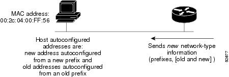
Simplified Network Renumbering for IPv6 Hosts
The strict aggregation of the global routing table requires that networks be renumbered when the service provider for the network is changed. When the stateless autoconfiguration functionality in IPv6 is used to renumber a network, the prefix from a new service provider is added to RA messages that are sent on the link. (The RA messages contain both the prefix from the old service provider and the prefix from the new service provider.) Nodes on the link automatically configure additional addresses by using the prefix from the new service provider. The nodes can then use the addresses created from the new prefix and the existing addresses created from the old prefix on the link. Configuration of the lifetime parameters associated with the old and new prefixes means that nodes on the link can make the transition to using only addresses created from the new prefix. During a transition period, the old prefix is removed from RA messages and only addresses that contain the new prefix are used on the link (the renumbering is complete) (see the figure below).
IPv6 General Prefixes
The upper 64 bits of an IPv6 address are composed from a global routing prefix plus a subnet ID, as defined in RFC 3513. A general prefix (for example, /48) holds a short prefix, based on which a number of longer, more specific prefixes (for example, /64) can be defined. When the general prefix is changed, all of the more specific prefixes based on it will change, too. This function greatly simplifies network renumbering and allows for automated prefix definition.
For example, a general prefix might be 48 bits long ("/48") and the more specific prefixes generated from it might be 64 bits long ("/64"). In the following example, the leftmost 48 bits of all the specific prefixes will be the same--and the same as the general prefix itself. The next 16 bits are all different.
- General prefix: 2001:DB8:2222::/48
- Specific prefix: 2001:DB8:2222:0000::/64
- Specific prefix: 2001:DB8:2222:0001::/64
- Specific prefix: 2001:DB8:2222:4321::/64
- Specific prefix: 2001:DB8:2222:7744::/64
General prefixes can be defined in several ways:
- Manually
- Based on a 6to4 interface
- Dynamically, from a prefix received by a DHCP for IPv6 prefix delegation client
More specific prefixes, based on a general prefix, can be used when configuring IPv6 on an interface.
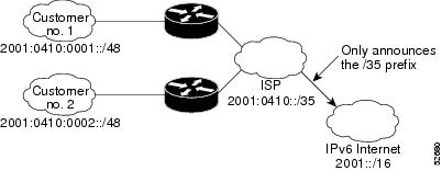
IPv6 Prefix Aggregation
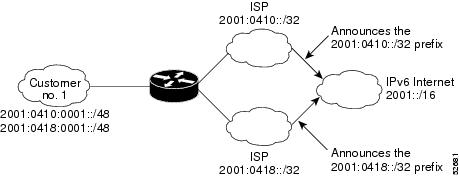
The aggregatable nature of the IPv6 address space enables an IPv6 addressing hierarchy. For example, an enterprise can subdivide a single IPv6 prefix from a service provider into multiple, longer prefixes for use within its internal network. Conversely, a service provider can aggregate all of the prefixes of its customers into a single, shorter prefix that the service provider can then advertise over the IPv6 internet (see the figure below).
IPv6 Site Multihoming
Multiple IPv6 prefixes can be assigned to networks and hosts. Having multiple prefixes assigned to a network makes it easy for that network to connect to multiple ISPs without breaking the global routing table (see the figure below).
IPv6 Data Links
In IPv6 networks, a data link is a network sharing a particular link-local prefix. Data links are networks arbitrarily segmented by a network administrator in order to provide a multilevel, hierarchical routing structure while shielding the subnetwork from the addressing complexity of attached networks. The function of a subnetwork in IPv6 is similar to a subnetwork in IPv4. A subnetwork prefix is associated with one data link; multiple subnetwork prefixes may be assigned to the same data link.
The following data links are supported for IPv6: ATM permanent virtual circuit (PVC) and ATM LANE, Ethernet, Fast Ethernet, Gigabit Ethernet, FDDI, Frame Relay PVC, Cisco High-Level Data Link Control (HDLC), PPP over Packet over SONET (PoS), ISDN, serial interfaces, and dynamic packet transport (DPT).
IPv6 for Cisco IOS Software Support for Wide-Area Networking Technologies
IPv6 for Cisco IOS software supports wide-area networking technologies such as Cisco HDLC, PoS, ISDN, and serial (synchronous and asynchronous) interface types, ATM PVCs, and Frame Relay PVCs. These technologies function the same in IPv6 as they do in IPv4--IPv6 does not enhance the technologies in any way.
IPv6 Addresses and PVCs
Broadcast and multicast are used in LANs to map protocol (network layer) addresses to the hardware addresses of remote nodes (hosts and routers). Because using broadcast and multicast to map network layer addresses to hardware addresses in circuit-based WANs such as ATM and Frame Relay networks is difficult to implement, these networks utilize implicit, explicit, and dynamic mappings for the network layer addresses of remote nodes and the PVCs used to reach the addresses.
Assigning an IPv6 address to an interface by using the ipv6 address command defines the IPv6 addresses for the interface and the network that is directly connected to the interface. If only one PVC is terminated on the interface (the interface is a point-to-point interface), there is an implicit mapping between all of the IPv6 addresses on the network and the PVC used to reach the addresses (no additional address mappings are needed). If several PVCs are terminated on the interface (the interface is a point-to-multipoint interface), the protocol ipv6 command (for ATM networks) or the frame-relay map ipv6 command (for Frame Relay networks) is used to configure explicit mappings between the IPv6 addresses of the remote nodes and the PVCs used to reach the addresses.
Note | Given that IPv6 supports multiple address types, and depending on which applications or protocols are configured on a point-to-multipoint interface, you may need to configure multiple explicit mappings between the IPv6 addresses of the interface and the PVC used to reach the addresses. For example, explicitly mapping both the link-local and global IPv6 address of a point-to-multipoint interface to the PVC on which the interface terminates ensures that the Interior Gateway Protocol (IGP) configured on the interface forwards traffic to and from the PVC correctly. |
Routed Bridge Encapsulation for IPv6
Routed bridge encapsulation (RBE) provides a mechanism for routing a protocol from a bridged interface to another routed or bridged interface. RBE for IPv6 can be used on ATM point-to-point subinterfaces that are configured for IPv6 half-bridging. Routing of IP packets and IPv6 half-bridging, bridging, PPP over Ethernet (PPPoE), or other Ethernet 802.3-encapsulated protocols can be configured on the same subinterface.
IPv6 Redirect Messages
The IPv6 Redirect Messages feature enables a router to send ICMP IPv6 neighbor redirect messages to inform hosts of better first hop nodes (routers or hosts) on the path to a destination.
IPv6 on BVI Interfaces for Bridging and Routing
Integrated routing and bridging (IRB) enables users to route a given protocol between routed interfaces and bridge groups or route a given protocol between bridge groups. Specifically, local or unroutable traffic will be bridged among the bridged interfaces in the same bridge group, while routable traffic will be routed to other routed interfaces or bridge groups. If you want both bridging and routing capabilities, IRB is required. If you want only bridging, you must disable routing. To disable the routing function in IPv4, you must configure the no ip routing command, and to disable the routing function for IPv6, you must configure the no ipv6 unicast-routing command.
IPv6 is supported in the BVI, which is the IPv4 interface for bridged interfaces. Because bridging is in the data-link layer and routing is in the network layer, they have different protocol configuration models to follow. In the basic IPv4 model, for example, all bridged interfaces should belong to the same network, while each routed interface represents a distinct network. Routed traffic is destined for the router, while bridged traffic is never destined for the router. Using BVI avoids the confusion of which protocol configuration model to use when both bridging and routing a given protocol in the same bridge group.
Note | BVIs in IPv6 are not supported with NAT-PT and wireless interfaces Dot11Radio. |
Dual IPv4 and IPv6 Protocol Stacks
The dual IPv4 and IPv6 protocol stack technique can be used to transition to IPv6. It enables gradual, one-by-one upgrades to applications running on nodes. Applications running on nodes are upgraded to make use of the IPv6 protocol stack. Applications that are not upgraded--they support only the IPv4 protocol stack--can coexist with upgraded applications on a node. New and upgraded applications make use of both the IPv4 and IPv6 protocol stacks (see the figure below).
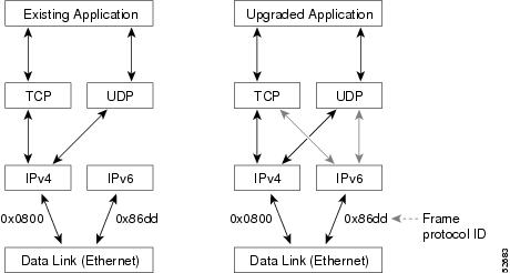
One application program interface (API) supports both IPv4 and IPv6 addresses and DNS requests. An application can be upgraded to the new API and still use only the IPv4 protocol stack. The Cisco IOS software supports the dual IPv4 and IPv6 protocol stack technique. When an interface is configured with both an IPv4 and an IPv6 address, the interface will forward both IPv4 and IPv6 traffic.
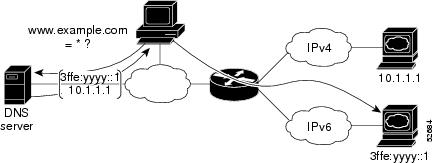
In the figure below, an application that supports dual IPv4 and IPv6 protocol stacks requests all available addresses for the destination hostname www.a.com from a DNS server. The DNS server replies with all available addresses (both IPv4 and IPv6 addresses) for www.example.com. The application chooses an address--in most cases, IPv6 addresses are the default choice--and connects the source node to the destination using the IPv6 protocol stack.
How to Implement IPv6 Addressing and Basic Connectivity
- Configuring IPv6 Addressing and Enabling IPv6 Routing
- Defining and Using IPv6 General Prefixes
- Configuring an Interface to Support the IPv4 and IPv6 Protocol Stacks
- Customizing IPv6 ICMP Rate Limiting
- Configuring the DRP Extension for Traffic Engineering
- Configuring Cisco Express Forwarding and Distributed Cisco Express Forwarding Switching for IPv6
- Mapping Hostnames to IPv6 Addresses
- Mapping IPv6 Addresses to IPv6 ATM and Frame Relay Interfaces
- Displaying IPv6 Redirect Messages
Configuring IPv6 Addressing and Enabling IPv6 Routing
Perform this task to assign IPv6 addresses to individual router interfaces and enable IPv6 traffic forwarding globally on the router. By default, IPv6 addresses are not configured and IPv6 routing is disabled.
Note | The ipv6-address argument in the ipv6 address command must be in the form documented in RFC 2373 where the address is specified in hexadecimal using 16-bit values between colons. The ipv6-prefix argument in the ipv6 address command must be in the form documented in RFC 2373 where the address is specified in hexadecimal using 16-bit values between colons. The / prefix-length keyword and argument in the ipv6 address command is a decimal value that indicates how many of the high-order contiguous bits of the address comprise the prefix (the network portion of the address). A slash mark must precede the decimal value. |
Note | In Cisco IOS Release 12.2(4)T or later releases, Cisco IOS Release 12.0(21)ST, and Cisco IOS Release 12.0(22)S or later releases, the ipv6 address or ipv6 address eui-64 command can be used to configure multiple IPv6 global addresses within the same prefix on an interface. Multiple IPv6 link-local addresses on an interface are not supported. Prior to Cisco IOS Releases 12.2(4)T, 12.0(21)ST, and 12.0(22)S, the Cisco IOS command-line interface (CLI) displays the following error message when multiple IPv6 addresses within the same prefix on an interface are configured: Prefix <prefix-number> already assigned to <interface-type> |
DETAILED STEPS
| Command or Action | Purpose | |
|---|---|---|
Step 1 |
enable
Example: Router> enable |
Enables privileged EXEC mode. |
Step 2 |
configure
terminal
Example: Router# configure terminal |
Enters global configuration mode. |
Step 3 |
interface
type
number
Example: Router(config)# interface ethernet 0/0 |
Specifies an interface type and number, and places the router in interface configuration mode. |
Step 4 | Do one of the following:
Example: Router(config-if)# ipv6 address 2001:DB8:0:1::/64 eui-64 Example: Router(config-if)# ipv6 address FE80::260:3EFF:FE11:6770 link-local Example: Router(config-if) ipv6 address 2001:DB8:1:1:FFFF:FFFF:FFFF:FFFE/64 anycast Example: Router(config-if)# ipv6 enable |
Specifies an IPv6 network assigned to the interface and enables IPv6 processing on the interface. or Specifies an IPv6 address assigned to the interface and enables IPv6 processing on the interface. or Automatically configures an IPv6 link-local address on the interface while also enabling the interface for IPv6 processing. The link-local address can be used only to communicate with nodes on the same link.
|
Step 5 |
exit
Example: Router(config-if)# exit |
Exits interface configuration mode, and returns the router to global configuration mode. |
Step 6 |
ipv6
unicast-routing
Example: Router(config)# ipv6 unicast-routing |
Enables the forwarding of IPv6 unicast datagrams. |
Configuring a Neighbor Discovery Cache Limit
- Configuring a Neighbor Discovery Cache Limit on a Specified Router Interface
- Configuring a Neighbor Discovery Cache Limit on All Router Interfaces
Configuring a Neighbor Discovery Cache Limit on a Specified Router Interface
DETAILED STEPS
| Command or Action | Purpose | |
|---|---|---|
Step 1 |
enable
Example: Router> enable |
Enables privileged EXEC mode. |
Step 2 |
configure
terminal
Example: Router# configure terminal |
Enters global configuration mode. |
Step 3 |
interface
type
number
Example: Router(config)# interface GigabitEthernet 1/0/0 |
Specifies an interface type and number, and places the router in interface configuration mode. |
Step 4 |
ipv6
nd
cache
interface-limit
size
[log
rate]
Example: Router(config-if)# ipv6 nd cache interface-limit 1 |
Configures a Neighbor Discovery cache limit on a specified interface on the router. |
Configuring a Neighbor Discovery Cache Limit on All Router Interfaces
DETAILED STEPS
| Command or Action | Purpose | |
|---|---|---|
Step 1 |
enable
Example: Router> enable |
Enables privileged EXEC mode. |
Step 2 |
configure
terminal
Example: Router# configure terminal |
Enters global configuration mode. |
Step 3 |
ipv6
nd
cache
interface-limit
size
[log
rate]
Example: Router(config)# ipv6 nd cache interface-limit 4 |
Configures a neighbor discovery cache limit on all interfaces on the router. |
Tuning the Parameters for IPv6 Neighbor Discovery
DETAILED STEPS
| Command or Action | Purpose | |
|---|---|---|
Step 1 |
enable
Example: Router> enable |
Enables privileged EXEC mode. |
Step 2 |
configure
terminal
Example: Router# configure terminal |
Enters global configuration mode. |
Step 3 |
interface
type
number
Example: Router(config)# interface GigabitEthernet 1/0/0 |
Specifies an interface type and number, and places the router in interface configuration mode. |
Step 4 |
ipv6
nd
nud
retry
base
interval
max-attempts
Example: Router(config-if)# ipv6 nd nud retry 1 1000 3 |
Configures the number of times NUD resends neighbor solicitations. |
Step 5 |
ipv6
nd
cache
expire
expire-time-in-seconds
[refresh]
Example: Router(config-if)# ipv6 nd cache expire 7200 |
Configures the length of time before an IPv6 ND cache entry expires. |
Step 6 |
ipv6
nd
na
glean
Example: Router(config-if)# ipv6 nd na glean |
Configures ND to glean an entry from an unsolicited NA. |
Defining and Using IPv6 General Prefixes
General prefixes can be defined in several ways:
- Manually
- Based on a 6to4 interface
- Dynamically, from a prefix received by a DHCP for IPv6 prefix delegation client
More specific prefixes, based on a general prefix, can be used when configuring IPv6 on an interface.
- Defining a General Prefix Manually
- Defining a General Prefix Based on a 6to4 Interface
- Defining a General Prefix with the DHCP for IPv6 Prefix Delegation Client Function
- Using a General Prefix in IPv6
Defining a General Prefix Manually
DETAILED STEPS
| Command or Action | Purpose | |
|---|---|---|
Step 1 |
enable
Example: Router> enable |
Enables privileged EXEC mode. |
Step 2 |
configure
terminal
Example: Router# configure terminal |
Enters global configuration mode. |
Step 3 |
ipv6
general-prefix
prefix-name
{ipv6-prefix/prefix-length |
6to4
interface-type
interface-number}
Example: Router(config)# ipv6 general-prefix my-prefix 2001:DB8:2222::/48 |
Defines a general prefix for an IPv6 address. |
Defining a General Prefix Based on a 6to4 Interface
DETAILED STEPS
| Command or Action | Purpose | |
|---|---|---|
Step 1 |
enable
Example: Router> enable |
Enables privileged EXEC mode. |
Step 2 |
configure
terminal
Example: Router# configure terminal |
Enters global configuration mode. |
Step 3 |
ipv6
general-prefix
prefix-name
{ipv6-prefix/prefix-length |
6to4
interface-type
interface-number}
Example: Router(config)# ipv6 general-prefix my-prefix 6to4 ethernet 0 |
Defines a general prefix for an IPv6 address.
|
Defining a General Prefix with the DHCP for IPv6 Prefix Delegation Client Function
You can define a general prefix dynamically using the DHCP for IPv6 prefix delegation client function. For information on how to perform this task, see the Implementing DHCP for IPv6 module.
Using a General Prefix in IPv6
DETAILED STEPS
| Command or Action | Purpose | |
|---|---|---|
Step 1 |
enable
Example: Router> enable |
Enables privileged EXEC mode. |
Step 2 |
configure
terminal
Example: Router# configure terminal |
Enters global configuration mode. |
Step 3 |
interface
type
number
Example: Router(config)# interface ethernet 0/0 |
Specifies an interface type and number, and places the router in interface configuration mode. |
Step 4 |
ipv6
address
{
ipv6-address/prefix-length
|
prefix-name
sub-bits/prefix-length}
Example: Router(config-if) ipv6 address my-prefix 2001:DB8:0:7272::/64 |
Configures an IPv6 prefix name for an IPv6 address and enables IPv6 processing on the interface. |
Configuring an Interface to Support the IPv4 and IPv6 Protocol Stacks
When an interface in a Cisco networking device is configured with both an IPv4 and an IPv6 address, the interface forwards both IPv4 and IPv6 traffic--the interface can send and receive data on both IPv4 and IPv6 networks. Perform this task to configure an interface in a Cisco networking device to support both the IPv4 and IPv6 protocol stacks.
DETAILED STEPS
| Command or Action | Purpose | |||
|---|---|---|---|---|
Step 1 |
enable
Example: Router> enable |
Enables privileged EXEC mode. | ||
Step 2 |
configure
terminal
Example: Router# configure terminal |
Enters global configuration mode. | ||
Step 3 |
ipv6
unicast-routing
Example: Router(config)# ipv6 unicast routing |
Enables the forwarding of IPv6 unicast datagrams. | ||
Step 4 |
interface
type
number
Example: Router(config)# interface ethernet 0 |
Specifies the interface type and number, and enters interface configuration mode. | ||
Step 5 |
ip address
ip-address
mask
[secondary [vrf
vrf-name]]
Example: Router(config-if)# ip address 192.168.99.1 255.255.255.0 |
Specifies a primary or secondary IPv4 address for an interface. | ||
Step 6 |
ipv6
address
{ipv6-address/prefix-length
|
prefix-name
sub-bits/prefix-length}
Example: Router(config-if)# ipv6 address 2001:DB8:c18:1::3/64 |
Specifies the IPv6 network assigned to the interface and enables IPv6 processing on the interface.
|
Customizing IPv6 ICMP Rate Limiting
DETAILED STEPS
| Command or Action | Purpose | |
|---|---|---|
Step 1 |
enable
Example: Router> enable |
Enables privileged EXEC mode.
|
Step 2 |
configure
terminal
Example: Router# configure terminal |
Enters global configuration mode. |
Step 3 |
ipv6
icmp
error-interval
milliseconds
[bucketsize] Example: Router(config)# ipv6 icmp error-interval 50 20 |
Configures the interval and bucket size for IPv6 ICMP error messages.
|
Configuring the DRP Extension for Traffic Engineering
DETAILED STEPS
| Command or Action | Purpose | |
|---|---|---|
Step 1 |
enable
Example: Router> enable |
Enables privileged EXEC mode. |
Step 2 |
configure
terminal
Example: Router# configure terminal |
Enters global configuration mode. |
Step 3 |
interface
type
number
Example: Router(config)# interface ethernet 0 |
Specifies the interface type and number, and enters interface configuration mode. |
Step 4 |
ipv6
nd
router-preference
{high |
medium |
low}
Example: Router(config-if)# ipv6 nd router-preference high |
Configures a DRP for a router on a specific interface. |
Configuring Cisco Express Forwarding and Distributed Cisco Express Forwarding Switching for IPv6
- Configuring Cisco Express Forwarding Switching on Distributed and Nondistributed Architecture Platforms
- Configuring Unicast RPF
Configuring Cisco Express Forwarding Switching on Distributed and Nondistributed Architecture Platforms
Cisco Express Forwarding is designed for nondistributed architecture platforms, such as the Cisco 7200 series routers. Distributed Cisco Express Forwarding is designed for distributed architecture platforms, such as the GSRs or the Cisco 7500 series routers. Nondistributed platforms do not support distributed Cisco Express Forwarding; however, some distributed platforms, such as the Cisco 7500 series routers, support both Cisco Express Forwarding and distributed Cisco Express Forwarding.
When Cisco Express Forwarding is configured on Cisco 7500 series routers, Cisco Express Forwarding switching is performed by the RP; when distributed Cisco Express Forwarding is configured, Cisco Express Forwarding switching is performed by the line cards. By default, the GSRs support only distributed Cisco Express Forwarding (Cisco Express Forwarding switching is performed by the line cards).
To enable the router to forward Cisco Express Forwarding and distributed Cisco Express Forwarding traffic, use the ipv6 unicast-routing command to configure the forwarding of IPv6 unicast datagrams globally on the router, and use the ipv6 address command to configure IPv6 address and IPv6 processing on an interface.
You must enable Cisco Express Forwarding for IPv4 globally on the router by using the ip cef command before enabling Cisco Express Forwarding for IPv6 globally on the router.
You must enable distributed Cisco Express Forwarding for IPv4 by using the ip cef distributed command before enabling distributed Cisco Express Forwarding for IPv6.
Note | The ipv6 cef and ipv6 cef distributed commands are not supported on the GSRs because this distributed platform operates only in distributed Cisco Express Forwarding mode. In Cisco IOS Release 12.0(22)S or later releases, the following restrictions apply to nondistributed and distributed architecture platforms configured for Cisco Express Forwarding and distributed Cisco Express Forwarding:
|
Note | By default, the GSRs support only distributed Cisco Express Forwarding (Cisco Express Forwarding switching is performed by the line cards). |
Note | Contact your local Cisco Systems account representative for specific Cisco Express Forwarding and distributed Cisco Express Forwarding hardware restrictions. |
DETAILED STEPS
| Command or Action | Purpose | |||
|---|---|---|---|---|
Step 1 |
enable
Example: Router> enable |
Enables privileged EXEC mode. | ||
Step 2 |
configure
terminal
Example: Router# configure terminal |
Enters global configuration mode. | ||
Step 3 |
Enables Cisco Express Forwarding globally on the router. or Enables distributed Cisco Express Forwarding globally on the router. | |||
Step 4 |
ipv6
cef
accounting
[non-recursive |
per-prefix |
prefix-length]
Example: Router(config)# ipv6 cef accounting |
Enables Cisco Express Forwarding and distributed Cisco Express Forwarding network accounting globally on the router.
|
Configuring Unicast RPF
To use Unicast RPF, enable Cisco Express Forwarding switching or distributed Cisco Express Forwarding switching in the router. There is no need to configure the input interface for Cisco Express Forwarding switching. As long as Cisco Express Forwarding is running on the router, individual interfaces can be configured with other switching modes.
Note | It is very important for Cisco Express Forwarding to be configured globally in the router. Unicast RPF will not work without Cisco Express Forwarding. |
Note | Unicast RPF should not be used on interfaces that are internal to the network. Internal interfaces are likely to have routing asymmetry, meaning that there are multiple routes to the source of a packet. Unicast RPF should be applied only where there is natural or configured symmetry. For example, routers at the edge of the network of an ISP are more likely to have symmetrical reverse paths than routers that are in the core of the ISP network. Routers that are in the core of the ISP network have no guarantee that the best forwarding path out of the router will be the path selected for packets returning to the router. Therefore, we do not recommend that you apply Unicast RPF where there is a chance of asymmetric routing. It is simplest to place Unicast RPF only at the edge of a network or, for an ISP, at the customer edge of the network. |
DETAILED STEPS
| Command or Action | Purpose | |
|---|---|---|
Step 1 |
enable
Example: Router> enable |
Enables privileged EXEC mode. |
Step 2 |
configure
terminal
Example: Router# configure terminal |
Enters global configuration mode. |
Step 3 |
interface
type
number
Example: Router(config)# interface atm 0 |
Specifies an interface type and number, and places the router in interface configuration mode. |
Step 4 |
ipv6
verify
unicast
source
reachable-via
{rx |
any} [allow-default] [allow-self-ping] [access-list-name]
Example: Router(config-if)# ipv6 verify unicast source reachable-via any |
Verifies that a source address exists in the FIB table and enables Unicast RPF. |
Mapping Hostnames to IPv6 Addresses
DETAILED STEPS
| Command or Action | Purpose | |||
|---|---|---|---|---|
Step 1 |
enable
Example: Router> enable |
Enables privileged EXEC mode. | ||
Step 2 |
configure
terminal
Example: Router# configure terminal |
Enters global configuration mode. | ||
Step 3 |
ipv6
host
name
[port]
ipv6-address1 [ipv6-address2...ipv6-address4]
Example: Router(config)# ipv6 host cisco-sj 2001:DB8:20:1::12 |
Defines a static hostname-to-address mapping in the hostname cache.
| ||
Step 4 |
(Optional) Defines a default domain name that the Cisco IOS software will use to complete unqualified hostnames. or (Optional) Defines a list of default domain names to complete unqualified hostnames.
| |||
Step 5 |
ip
name-server
[vrf
vrf-name]
server-address1 [server-address2...server-address6]
Example: Router(config)# ip name-server 2001:DB8::250:8bff:fee8:f800 2001:DB8:0:f004::1 |
Specifies one or more hosts that supply name information.
| ||
Step 6 |
ip
domain-lookup
Example: Router(config)# ip domain-lookup |
Enables DNS-based address translation. |
Mapping IPv6 Addresses to IPv6 ATM and Frame Relay Interfaces
Perform this task to map IPv6 addresses to ATM and Frame Relay PVCs. Specifically, the steps in this section explain how to explicitly map IPv6 addresses to the ATM and Frame Relay PVCs used to reach the addresses.
Note | This task shows how to configure both ATM and Frame Relay PVCs. Many of the steps are labeled optional because many networks will require only one type of PVC to be configured. The steps in this section are not applicable to ATM LANE. |
DETAILED STEPS
| Command or Action | Purpose | |
|---|---|---|
Step 1 |
enable
Example: Router> enable |
Enables privileged EXEC mode. |
Step 2 |
configure
terminal
Example: Router# configure terminal |
Enters global configuration mode. |
Step 3 |
interface
type
number
Example: Router(config)# interface atm 0 |
Specifies an interface type and number, and places the router in interface configuration mode. |
Step 4 |
pvc
[
name
]
vpi/vci [ces |
ilmi |
qsaal |
smds |
l2transport]
Example: Router(config-if)# pvc 1/32 |
(Optional) Creates or assigns a name to an ATM PVC and places the router in ATM VC configuration mode. |
Step 5 |
protocol
ipv6
ipv6-address
[[no]
broadcast]
Example: Router(config-if-atm-vc)# protocol ipv6 2001:DB8:2222:1003::45 |
(Optional) Maps the IPv6 address of a remote node to the PVC used to reach the address.
|
Step 6 |
exit
Example: Router(config-if-atm-vc)# exit |
Exits ATM VC configuration mode, and returns the router to interface configuration mode. |
Step 7 |
ipv6
address
ipv6-address/prefix-length
link-local
Example: Router(config-if)# ipv6 address 2001:DB8:2222:1003::72/64 link-local |
Specifies an IPv6 network assigned to the interface and enables IPv6 processing on the interface.
|
Step 8 |
exit
Example: Router(config-if)# exit |
Exits interface configuration mode, and returns the router to global configuration mode. |
Step 9 |
interface
type
number
Example: Router(config)# interface serial 3 |
Specifies an interface type and number, and places the router in interface configuration mode. |
Step 10 |
frame-relay
map
ipv6
ipv6-address
dlci
[broadcast] [cisco] [ietf] [payload-compression {packet-by-packet |
frf9
stac [hardware-options] |
data-stream
stac [hardware-options]}]
Example: Router(config-if)# frame-relay map ipv6 FE80::E0:F727:E400:A 17 broadcast |
(Optional) Maps the IPv6 address of a remote node to the data-link connection identifier (DLCI) of the PVC used to reach the address. |
Step 11 |
ipv6
address
ipv6-address/prefix-length
link-local
Example: Router(config-if)# ipv6 address 2001:DB8:2222:1044::46/64 link-local |
Specifies an IPv6 network assigned to the interface and enables IPv6 processing on the interface.
|
Displaying IPv6 Redirect Messages
Perform this task to display IPv6 redirect messages. The commands shown are optional and can be entered in any order.
DETAILED STEPS
| Command or Action | Purpose | |
|---|---|---|
Step 1 |
enable
Example: Router# enable |
Enables privileged EXEC mode. |
Step 2 |
show
ipv6
interface
[brief] [type
number] [prefix]
Example: Router# show ipv6 interface ethernet 0 |
Displays the usability status of interfaces configured for IPv6. |
Step 3 |
show
ipv6
neighbors
[interface-type
interface-number |
ipv6-address |
ipv6-hostname |
statistics]
Example: Router# show ipv6 neighbors ethernet 2 |
Displays IPv6 neighbor discovery cache information. |
Step 4 |
show
ipv6
route
[ipv6-address |
ipv6-prefix/prefix-length |protocol |
interface-type
interface-number]
Example: Router# show ipv6 route |
Displays the current contents of the IPv6 routing table. |
Step 5 |
show
ipv6
traffic
Example: Router# show ipv6 traffic |
Displays statistics about IPv6 traffic. |
Step 6 |
show
frame-relay
map
[interface
type
number] [dlci]
Example: Router# show frame-relay map |
Displays the current map entries and information about the Frame Relay connections. |
Step 7 |
show
atm
map
Example: Router# show atm map |
Displays the list of all configured ATM static maps to remote hosts on an ATM network and on ATM bundle maps. |
Step 8 |
show hosts
[vrf
vrf-name |
all |
hostname |
summary]
Example: Router# show hosts |
Displays the default domain name, the style of name lookup service, a list of name server hosts, and the cached list of hostnames and addresses. |
Step 9 |
show
running-config
Example: Router# show running-config |
Displays the current configuration running on the router. |
Examples
Sample Output from the show ipv6 interface Command
In the following example, the show ipv6 interface command is used to verify that IPv6 addresses are configured correctly for Ethernet interface 0. Information is also displayed about the status of IPv6 neighbor redirect messages, IPv6 neighbor discovery messages, and stateless autoconfiguration.
Router# show ipv6 interface ethernet 0

Ethernet0 is up, line protocol is up
  IPv6 is stalled, link-local address is FE80::1
  Global unicast address(es):
    2001:DB8:2000::1, subnet is 2001:DB8:2000::/64
    2001:DB8:3000::1, subnet is 2001:DB8:3000::/64
  Joined group address(es):
    FF02::1
    FF02::2
    FF02::1:FF00:1
  MTU is 1500 bytes
  ICMP error messages limited to one every 100 milliseconds
  ICMP redirects are enabled
  ND DAD is enabled, number of DAD attempts: 1
  ND reachable time is 30000 milliseconds
  ND advertised reachable time is 0 milliseconds
  ND advertised retransmit interval is 0 milliseconds
  ND router advertisements are sent every 200 seconds
  ND router advertisements live for 1800 seconds
  Hosts use stateless autoconfig for addresses.
Sample Output from the show ipv6 neighbors Command
In the following example, the show ipv6 neighbors command is used to display IPv6 neighbor discovery cache information. A hyphen (-) in the Age field of the command output indicates a static entry. The following example displays IPv6 neighbor discovery cache information for Ethernet interface 2:
Router# show ipv6 neighbors ethernet 2

IPv6 Address                              Age Link-layer Addr State Interface
2001:DB8:0:4::2                            0 0003.a0d6.141e  REACH Ethernet2
FE80::XXXX:A0FF:FED6:141E                   0 0003.a0d6.141e  REACH Ethernet2
2001:DB8:1::45a                            - 0002.7d1a.9472  REACH Ethernet2
Sample Output from the show ipv6 route Command
When the ipv6-address or ipv6-prefix/prefix-length argument is specified, only route information for that address or network is displayed. The following is sample output from the show ipv6 route command when entered with the IPv6 prefix 2001:DB8::/35:
Router# show ipv6 route 2001:DB8::/35

IPv6 Routing Table - 261 entries
Codes: C - Connected, L - Local, S - Static, R - RIP, B - BGP
I1 - ISIS L1, I2 - ISIS L2, IA - ISIS interarea
B 2001:DB8::/35 [20/3]
  via FE80::60:5C59:9E00:16, Tunnel1
Sample Output from the show ipv6 traffic Command
In the following example, the show ipv6 traffic command is used to display ICMP rate-limited counters:
Router# show ipv6 traffic

ICMP statistics:
  Rcvd: 188 input, 0 checksum errors, 0 too short
        0 unknown info type, 0 unknown error type
        unreach: 0 routing, 0 admin, 0 neighbor, 0 address, 0 port
        parameter: 0 error, 0 header, 0 option
        0 hopcount expired, 0 reassembly timeout,0 too big
        0 echo request, 0 echo reply
        0 group query, 0 group report, 0 group reduce
        1 router solicit, 175 router advert, 0 redirects
        0 neighbor solicit, 12 neighbor advert
  Sent: 7376 output, 56 rate-limited
        unreach: 0 routing, 15 admin, 0 neighbor, 0 address, 0 port
        parameter: 0 error, 0 header, 0 option
        0 hopcount expired, 0 reassembly timeout,0 too big
        15 echo request, 0 echo reply
        0 group query, 0 group report, 0 group reduce
        0 router solicit, 7326 router advert, 0 redirects
        2 neighbor solicit, 22 neighbor advert
Sample Output from the show frame-relay map Command
In the following example, the show frame-relay map command is used to verify that the IPv6 address of a remote node is mapped to the DLCI of the PVC used to reach the address. The following example shows that the link-local and global IPv6 addresses (FE80::E0:F727:E400:A and 2001:DB8:2222:1044::73; FE80::60:3E47:AC8:8 and 2001.DB8:2222:1044::72) of two remote nodes are explicitly mapped to DLCI 17 and DLCI 19, respectively. Both DLCI 17 and DLCI 19 are terminated on interface serial 3 of this node; therefore, interface serial 3 of this node is a point-to-multipoint interface.
Router# show frame-relay map

Serial3 (up): ipv6 FE80::E0:F727:E400:A dlci 17(0x11,0x410), static,
              broadcast, CISCO, status defined, active
Serial3 (up): ipv6 2001:DB8:2222:1044::72 dlci 19(0x13,0x430), static,
              CISCO, status defined, active
Serial3 (up): ipv6 2001:DB8:2222:1044::73 dlci 17(0x11,0x410), static,
              CISCO, status defined, active
Serial3 (up): ipv6 FE80::60:3E47:AC8:8 dlci 19(0x13,0x430), static,
              broadcast, CISCO, status defined, active
Sample Output from the show atm map Command
In the following example, the show atm map command is used to verify that the IPv6 address of a remote node is mapped to the PVC used to reach the address. The following example shows that the link-local and global IPv6 addresses (FE80::60:3E47:AC8:C and 2001:DB8:2222:1003::72, respectively) of a remote node are explicitly mapped to PVC 1/32 of ATM interface 0:
Router# show atm map

Map list ATM0pvc1 : PERMANENT
ipv6 FE80::60:3E47:AC8:C maps to VC 1, VPI 1, VCI 32, ATM0
        , broadcast
ipv6 2001:DB8:2222:1003::72 maps to VC 1, VPI 1, VCI 32, ATM0
Sample Output from the show hosts Command
The state of the name lookup system on the DHCP for IPv6 client can be displayed with the show hosts command:
Router# show hosts

Default domain is not set
Domain list:example.com
Name/address lookup uses domain service
Name servers are 2001:DB8:A:B::1, 2001:DB8:3000:3000::42
Codes:UN - unknown, EX - expired, OK - OK, ?? - revalidate
       temp - temporary, perm - permanent
       NA - Not Applicable None - Not defined
Host                      Port  Flags      Age Type   Address(es)
sdfasfd                   None  (temp, UN)  0  IPv6
Sample Output from the show running-config Command
In the following example, the show running-config command is used to verify that IPv6 processing of packets is enabled globally on the router and on applicable interfaces, and that an IPv6 address is configured on applicable interfaces:
Router# show running-config

Building configuration...
Current configuration : 22324 bytes
!
! Last configuration change at 14:59:38 PST Tue Jan 16 2001
! NVRAM config last updated at 04:25:39 PST Tue Jan 16 2001 by bird
!
hostname Router
!
ipv6 unicast-routing
!
interface Ethernet0
 no ip route-cache
 no ip mroute-cache
 no keepalive
 media-type 10BaseT
	ipv6 address 2001:DB8:0:1::/64 eui-64
!
In the following example, the show running-config command is used to verify that Cisco Express Forwarding and network accounting for Cisco Express Forwarding have been enabled globally on a nondistributed architecture platform, and that Cisco Express Forwarding has been enabled on an IPv6 interface. The following output shows that both that Cisco Express Forwarding and network accounting for Cisco Express Forwarding have been enabled globally on the router, and that Cisco Express Forwarding has also been enabled on Ethernet interface 0:
Router# show running-config

Building configuration...
Current configuration : 22324 bytes
!
! Last configuration change at 14:59:38 PST Tue Jan 16 2001
! NVRAM config last updated at 04:25:39 PST Tue Jan 16 2001 by bird
!
hostname Router
!
ip cef
ipv6 unicast-routing
ipv6 cef
ipv6 cef accounting prefix-length
!
!
interface Ethernet0
 ip address 10.4.9.11 255.0.0.0
 media-type 10BaseT
 ipv6 address 2001:DB8:C18:1::/64 eui-64
!
In the following example, the show running-config command is used to verify that distributed Cisco Express Forwarding and network accounting for distributed Cisco Express Forwarding have been enabled globally on a distributed architecture platform, such as the Cisco 7500 series routers. The following example shows that both distributed Cisco Express Forwarding and network accounting for Cisco Express Forwarding have been enabled globally on the router.
Note | Distributed Cisco Express Forwarding is enabled by default on the GSRs and disabled by default on the Cisco 7500 series routers. Therefore, output from the show running-config command on the GSRs does not show whether distributed Cisco Express Forwarding is configured globally on the router. The following output is from a Cisco 7500 series router. |
Router# show running-config

Building configuration...
Current configuration : 22324 bytes
!
! Last configuration change at 14:59:38 PST Tue Jan 16 2001
! NVRAM config last updated at 04:25:39 PST Tue Jan 16 2001 by bird
!
hostname Router
!
ip cef distributed
ipv6 unicast-routing
ipv6 cef distributed
ipv6 cef accounting prefix-length
In the following example, the show running-config command is used to verify static hostname-to-address mappings, default domain names, and name servers in the hostname cache, and to verify that the DNS service is enabled:
Router# show running-config

Building configuration...
!
ipv6 host cisco-sj 2001:DB8:20:1::12
!
ip domain-name cisco.com
ip domain-lookup
ip name-server 2001:DB8:C01F:768::1
Configuration Examples for Implementing IPv6 Addressing and Basic Connectivity
- Example: IPv6 Addressing and IPv6 Routing Configuration
- Example: Dual Protocol Stacks Configuration
- Example: IPv6 ICMP Rate Limiting Configuration
- Example: Cisco Express Forwarding and Distributed Cisco Express Forwarding Configuration
- Example: Hostname-to-Address Mappings Configuration
- Examples: IPv6 Address to ATM and Frame Relay PVC Mapping Configuration
Example: IPv6 Addressing and IPv6 Routing Configuration
In the following example, IPv6 is enabled on the router with both a link-local address and a global address based on the IPv6 prefix 2001:DB8:c18:1::/64. The EUI-64 interface ID is used in the low-order 64 bits of both addresses. Output from the show ipv6 interface command is included to show how the interface ID (260:3EFF:FE47:1530) is appended to the link-local prefix FE80::/64 of Ethernet interface 0.
ipv6 unicast-routing
interface ethernet 0
  ipv6 address 2001:DB8:c18:1::/64 eui-64

Router# show ipv6 interface ethernet 0

Ethernet0 is up, line protocol is up
 IPv6 is enabled, link-local address is FE80::260:3EFF:FE47:1530
  Global unicast address(es):
    2001:DB8:C18:1:260:3EFF:FE47:1530, subnet is 2001:DB8:C18:1::/64
  Joined group address(es):
    FF02::1
    FF02::2
    FF02::1:FF47:1530
    FF02::9
  MTU is 1500 bytes
  ICMP error messages limited to one every 500 milliseconds
  ND reachable time is 30000 milliseconds
  ND advertised reachable time is 0 milliseconds
  ND advertised retransmit interval is 0 milliseconds
  ND router advertisements are sent every 200 seconds
  ND router advertisements live for 1800 seconds
  Hosts use stateless autoconfig for addresses.
In the following example, multiple IPv6 global addresses within the prefix 2001:DB8::/64 are configured on Ethernet interface 0:
interface ethernet 0
 ipv6 address 2001:DB8::1/64
 ipv6 address 2001:DB8::/64 eui-64
Example: Tuning the Parameters for IPv6 Neighbor Discovery
In the following examples, IPv6 ND NA gleaning is enabled and the IPv6 ND cache expiry is set to 7200 seconds (2 hours):
interface Port-channel189
 no ip address
 ipv6 address FC07::789:1:0:0:3/64
 ipv6 nd reachable-time 2700000
 ipv6 nd na glean
 ipv6 nd cache expire 7200
 no ipv6 redirects
 standby version 2
 standby 2 ipv6 FC07::789:1:0:0:1/64
 standby 2 priority 150
 standby 2 preempt
Example: Cisco Express Forwarding and Distributed Cisco Express Forwarding Configuration
In the following example, both Cisco Express Forwarding for IPv6 and network accounting for Cisco Express Forwarding for IPv6 have been enabled globally on a nondistributed architecture router, and Cisco Express Forwarding for IPv6 has been enabled on Ethernet interface 0. The example also shows that the forwarding of IPv6 unicast datagrams has been configured globally on the router with the ipv6 unicast-routing command, an IPv6 address has been configured on Ethernet interface 0 with the ipv6 address command, and Cisco Express Forwarding for IPv4 has been configured globally on the router with the ip cef command.
ip cef
ipv6 unicast-routing
ipv6 cef
ipv6 cef accounting prefix-length
interface Ethernet0
 ip address 10.4.9.11 255.0.0.0
 media-type 10BaseT
 ipv6 address 2001:DB8:C18:1::/64 eui-64
In the following example, both distributed Cisco Express Forwarding for IPv6 and network accounting for distributed Cisco Express Forwarding for IPv6 have been enabled globally on a distributed architecture router. The forwarding of IPv6 unicast datagrams has been configured globally on the router with the ipv6 unicast-routing command and distributed Cisco Express Forwarding for IPv4 has been configured globally on the router with the ip cef distributed command.
ip cef distributed
ipv6 unicast-routing
ipv6 cef distributed
ipv6 cef accounting prefix-length
Example: Hostname-to-Address Mappings Configuration
The following example defines two static hostname-to-address mappings in the hostname cache, establishes a domain list with several alternate domain names to complete unqualified hostnames, specifies host 2001:DB8::250:8bff:fee8:f800 and host 2001:DB8:0:f004::1 as the name servers, and reenables the DNS service:
ipv6 host cisco-sj 2001:DB8:700:20:1::12
ipv6 host cisco-hq 2001:DB8:768::1 2001:DB8:20:1::22
ip domain list domain1-list.com
ip domain list serviceprovider2-name.com
ip domain list college2-name.edu
ip name-server 2001:DB8::250:8bff:fee8:f800 2001:DB8:0:f004::1
ip domain-lookup
Examples: IPv6 Address to ATM and Frame Relay PVC Mapping Configuration
- Example: IPv6 ATM PVC Mapping Configuration (Point-to-Point Interface)
- Example: IPv6 ATM PVC Mapping Configuration (Point-to-Multipoint Interface)
- Example: IPv6 Frame Relay PVC Mapping Configuration (Point-to-Point Interface)
- Example: IPv6 Frame Relay PVC Mapping Configuration (Point-to-Multipoint Interface)
Example: IPv6 ATM PVC Mapping Configuration (Point-to-Point Interface)
In the following example, two nodes named Router 1 and Router 2 are connected by a single PVC. The point-to-point subinterface ATM0.132 is used on both nodes to terminate the PVC; therefore, the mapping between the IPv6 addresses of both nodes and the PVC is implicit (no additional mappings are required).
Example: IPv6 ATM PVC Mapping Configuration (Point-to-Multipoint Interface)
In the following example, the same two nodes (Router 1 and Router 2) from the previous example are connected by the same PVC. In this example, however, the point-to-multipoint interface ATM0 is used on both nodes to terminate the PVC; therefore, explicit mappings are required between the link-local and global IPv6 addresses of interface ATM0 on both nodes and the PVC. Additionally, ATM pseudobroadcasts are enabled on the link-local address of interface ATM0 on both nodes. The link-local address specified here is the link-local address of the other end of the PVC.
Example: IPv6 Frame Relay PVC Mapping Configuration (Point-to-Point Interface)
In the following example, three nodes named Router A, Router B, and Router C make up a fully meshed network. Each node is configured with two PVCs, which provide an individual connection to each of the other two nodes. Each PVC is configured on a different point-to-point subinterface, which creates three unique IPv6 networks (2001:DB8:2222:1017:/64, 2001:DB8:2222:1018::/64, and 2001:DB8:2222:1019::/64). Therefore, the mappings between the IPv6 addresses of each node and the DLCI (DLCI 17, 18, and 19) of the PVC used to reach the addresses are implicit (no additional mappings are required).
Note | Given that each PVC in the following example is configured on a different point-to-point subinterface, the configuration in the following example can also be used in a network that is not fully meshed. Additionally, configuring each PVC on a different point-to-point subinterface can help simplify your routing protocol configuration. However, the configuration in the following example requires more than one IPv6 network, whereas configuring each PVC on point-to-multipoint interfaces requires only one IPv6 network. |
Router A Configuration
interface Serial 3
 encapsulation frame-relay
!
interface Serial3.17 point-to-point
 description to Router B
 ipv6 address 2001:DB8:2222:1017::46/64
 frame-relay interface-dlci 17
!
interface Serial 3.19 point-to-point
 description to Router C
 ipv6 address 2001:DB8:2222:1019::46/64
 frame-relay interface-dlci 19
Router B Configuration
interface Serial 5
 encapsulation frame-relay
!
interface Serial5.17 point-to-point
 description to Router A
 ipv6 address 2001:DB8:2222:1017::73/64
 frame-relay interface-dlci 17
!
interface Serial5.18 point-to-point
 description to Router C
 ipv6 address 2001:DB8:2222:1018::73/64
 frame-relay interface-dlci 18
Router C Configuration
interface Serial 0
 encapsulation frame-relay
!
interface Serial0.18 point-to-point
 description to Router B
 ipv6 address 2001:DB8:2222:1018::72/64
 frame-relay interface-dlci 18
!
interface Serial0.19 point-to-point
 description to Router A
 ipv6 address 2001:DB8:2222:1019::72/64
 frame-relay interface-dlci 19
Example: IPv6 Frame Relay PVC Mapping Configuration (Point-to-Multipoint Interface)
In the following example, the same three nodes (Router A, Router B, and Router C) from the previous example make up a fully meshed network and each node is configured with two PVCs (which provide an individual connection to each of the other two nodes). However, the two PVCs on each node in the following example are configured on a single interface (serial 3, serial 5, and serial 10, respectively), which makes each interface a point-to-multipoint interface. Therefore, explicit mappings are required between the link-local and global IPv6 addresses of each interface on all three nodes and the DLCI (DLCI 17, 18, and 19) of the PVC used to reach the addresses.
Router A Configuration
interface Serial 3
 encapsulation frame-relay
 ipv6 address 2001:DB8:2222:1044::46/64
 frame-relay map ipv6 FE80::E0:F727:E400:A 17 broadcast
 frame-relay map ipv6 FE80::60:3E47:AC8:8 19 broadcast
 frame-relay map ipv6 2001:DB8:2222:1044::72 19
 frame-relay map ipv6 2001:DB8:2222:1044::73 17
Router B Configuration
interface Serial 5
 encapsulation frame-relay
 ipv6 address 2001:DB8:2222:1044::73/64
 frame-relay map ipv6 FE80::60:3E59:DA78:C 17 broadcast
 frame-relay map ipv6 FE80::60:3E47:AC8:8 18 broadcast
 frame-relay map ipv6 2001:DB8:2222:1044::46 17
 frame-relay map ipv6 2001:DB8:2222:1044::72 18
Router C Configuration
interface Serial 10
 encapsulation frame-relay
 ipv6 address 2001:DB8:2222:1044::72/64
 frame-relay map ipv6 FE80::60:3E59:DA78:C 19 broadcast
 frame-relay map ipv6 FE80::E0:F727:E400:A 18 broadcast
 frame-relay map ipv6 2001:DB8:2222:1044::46 19
 frame-relay map ipv6 2001:DB8:2222:1044::73 18
Additional References
Related Documents
|
Related Topic |
Document Title |
|---|---|
|
IPv6 supported feature list |
"Start Here: Cisco IOS Software Release Specifics for IPv6 Features," Cisco IOS IPv6 Configuration Guide |
|
IPv6 commands: complete command syntax, command mode, command history, defaults, usage guidelines, and examples |
Cisco IOS IPv6 Command Reference |
|
IPv6 DHCP description and configuration |
"Implementing DHCP for IPv6," Cisco IOS IPv6 Configuration Guide |
|
IPv4 addressing configuration tasks |
"Configuring IPv4 Addresses," Cisco IOS IP Addressing Services Configuration Guide |
|
IPv4 services configuration tasks |
"Configuring IP Services," Cisco IOS IP Application Services Configuration Guide |
|
IPv4 addressing commands |
Cisco IOS IP Addressing Services Command Reference |
|
IPv4 IP services commands |
Cisco IOS IP Application Services Command Reference |
|
Stateful switchover |
"Stateful Switchover," Cisco IOS High Availability Configuration Guide |
|
Switching configuration tasks |
Cisco IOS IP Switching Configuration Guide |
|
Switching commands |
Cisco IOS IP Switching Command Reference |
MIBs
RFCs
|
RFCs |
Title |
|---|---|
|
RFC 1981 |
Path MTU Discovery for IP version 6 |
|
RFC 2373 |
IP Version 6 Addressing Architecture |
|
RFC 2374 |
An Aggregatable Global Unicast Address Format |
|
RFC 2460 |
Internet Protocol, Version 6 (IPv6) Specification |
|
RFC 2461 |
Neighbor Discovery for IP Version 6 (IPv6) |
|
RFC 2462 |
IPv6 Stateless Address Autoconfiguration |
|
RFC 2463 |
Internet Control Message Protocol (ICMPv6) for the Internet Protocol Version 6 (IPv6) Specification |
|
RFC 2464 |
Transmission of IPv6 Packets over Ethernet Networks |
|
RFC 2467 |
Transmission of IPv6 Packets over FDDI Networks |
|
RFC 2472 |
IP Version 6 over PPP |
|
RFC 2492 |
IPv6 over ATM Networks |
|
RFC 2590 |
Transmission of IPv6 Packets over Frame Relay Networks Specification |
|
RFC 2684 |
Multiprotocol Encapsulation over ATM Adaptation Layer 5 |
|
RFC 3152 |
Delegation of IP6.ARPA |
|
RFC 3162 |
RADIUS and IPv6 |
|
RFC 3513 |
Internet Protocol Version 6 (IPv6) Addressing Architecture |
|
RFC 3596 |
DNS Extensions to Support IP version 6 |
|
RFC 3879 |
Deprecating Site Local Addresses |
|
RFC 4193 |
Unique Local IPv6 Unicast Addresses |
Technical Assistance
|
Description |
Link |
|---|---|
|
The Cisco Support and Documentation website provides online resources to download documentation, software, and tools. Use these resources to install and configure the software and to troubleshoot and resolve technical issues with Cisco products and technologies. Access to most tools on the Cisco Support and Documentation website requires a Cisco.com user ID and password. |
Feature Information for Implementing IPv6 Addressing and Basic Connectivity
The following table provides release information about the feature or features described in this module. This table lists only the software release that introduced support for a given feature in a given software release train. Unless noted otherwise, subsequent releases of that software release train also support that feature.
Use Cisco Feature Navigator to find information about platform support and Cisco software image support. To access Cisco Feature Navigator, go to www.cisco.com/go/cfn. An account on Cisco.com is not required.
| Table 5 | Feature Information for Implementing IPv6 Addressing and Basic Connectivity |
|
Feature Name |
Releases |
Feature Information |
|---|---|---|
|
IPv6--Anycast Address |
12.2(25)S 12.2(28)SB 12.2(25)SG 12.2(33)SRA 12.2(33)SXH 12.3(4)T 12.4 12.4(2)T |
An anycast address is an address that is assigned to a set of interfaces that typically belong to different nodes. |
|
IPv6--Base Protocols High Availability |
12.2(33)SRE |
IPv6 neighbor discovery supports SSO. |
|
IPv6--ICMP Rate Limiting |
12.2(8)T 12.3 12.3(2)T 12.4 12.4(2)T |
The IPv6 ICMP Rate Limiting feature implements a token bucket algorithm for limiting the rate at which IPv6 ICMP error messages are sent out on the network. |
|
IPv6--ICMPv6 |
12.0(22)S 12.2(14)S 12.2(28)SB 12.2(25)SG 12.2(33)SRA 12.2(17a)SX1 12.2(2)T 12.3 12.3(2)T 12.4 12.4(2)T |
ICMP for IPv6 generates error messages, such as ICMP destination unreachable messages, and informational messages, such as ICMP echo request and reply messages. Additionally, ICMP packets in IPv6 are used in the IPv6 neighbor discovery process, path MTU discovery, and the MLD protocol for IPv6. |
|
IPv6--ICMPv6 Redirect |
12.0(22)S 12.2(14)S 12.2(28)SB 12.2(25)SG 12.2(33)SRA 12.2(17a)SX1 12.2(4)T 12.3 12.3(2)T 12.4 12.4(2)T |
A value of 137 in the Type field of the ICMP packet header identifies an IPv6 neighbor redirect message. Routers send neighbor redirect messages to inform hosts of better first-hop nodes on the path to a destination. |
|
IPv6--IPv6 Default Router Preferences |
12.2(33)SB 12.2(33)SRA 12.4(2)T 12.2(33)SXH 15.0(1)S |
The DRP extension provides a coarse preference metric (low, medium, or high) for default routers. |
|
IPv6--IPv6 MTU Path Discovery |
12.0(22)S 12.2(14)S 12.2(28)SB 12.2(25)SG 12.2(33)SRA 12.2(17a)SX1 12.2(2)T 12.3 12.3(2)T 12.4 12.4(2)T 15.0(1)S |
Path MTU discovery in IPv6 allows a host to dynamically discover and adjust to differences in the MTU size of every link along a given data path. |
|
IPv6--IPv6 Neighbor Discovery |
12.0(22)S 12.2(14)S 12.2(28)SB 12.2(25)SG 12.2(33)SRA 12.2(17a)SX1 12.2(2)T 12.3 12.3(2)T 12.4 12.4(2)T 15.0(1)S |
The IPv6 neighbor discovery process uses ICMP messages and solicited-node multicast addresses to determine the link-layer address of a neighbor on the same network (local link), verify the reachability of a neighbor, and track neighboring routers. |
|
IPv6--IPv6 Neighbor Discovery Duplicate Address Detection |
12.0(22)S 12.2(14)S 12.2(28)SB 12.2(25)SG 12.2(33)SRA 12.2(17a)SX1 12.2(4)T 12.3 12.3(2)T 12.4 12.4(2)T |
IPv6 neighbor discovery duplicate address detection is performed first on a new, link-local IPv6 address before the address is assigned to an interface (the new address remains in a tentative state while duplicate address detection is performed). |
|
IPv6--IPv6 Stateless Autoconfiguration |
12.0(22)S 12.2(14)S 12.2(28)SB 12.2(25)SG 12.2(33)SRA 12.2(17a)SX1 12.2(2)T 12.3 12.3(2)T 12.4 12.4(2)T 15.0(1)S |
The IPv6 Stateless Autoconfiguration feature can be used to manage link, subnet, and site addressing changes. |
|
IPv6--IPv6 Static Cache Entry for Neighbor Discovery |
12.0(22)S 12.2(14)S 12.2(28)SB 12.2(33)SRA 12.2(17a)SX1 12.2(8)T 12.3 12.3(2)T 12.4 12.4(2)T 15.0(1)S |
The IIPv6 Static Cache Entry for Neighbor Discovery feature allows static entries to be made in the IPv6 neighbor cache. |
|
IPv6--Per-Interface Neighbor Discovery Cache Limit |
15.1(3)T |
The Per-Interface Neighbor Discovery Cache Limit feature provides the ability to limit the number of neighbor discovery cache entries on a per interface basis. The following commands were introduced or modified for this feature: ipv6 nd cache interface-limit (global), ipv6 nd cache interface-limit (interface), show ipv6 neighbors. |
|
IPv6 Access Services: Routed Bridged Encapsulation (RBE) |
12.3(4)T 12.4 12.4(2)T |
RBE provides a mechanism for routing a protocol from a bridged interface to another routed or bridged interface. |
|
IPv6 Address Types--Unicast |
12.0(22)S 12.2(14)S 12.2(28)SB 12.2(33)SRA 12.2(17a)SX1 12.2(2)T 12.3 12.3(2)T 12.4 12.4(2)T |
An IPv6 unicast address is an identifier for a single interface, on a single node. |
|
IPv6 Data Link--ATM PVC and ATM LANE |
12.0(22)S 12.2(14)S 12.2(28)SB 12.2(33)SRA 12.2(2)T 12.3 12.3(2)T 12.4 12.4(2)T |
In IPv6 networks, a data link is a network sharing a particular link-local prefix. ATM PVC and ATM LANE are data links supported for IPv6. |
|
IPv6 Data Link--Cisco High-Level Data Link Control (HDLC) |
12.0(22)S 12.2(14)S 12.2(28)SB 12.2(33)SRA 12.2(2)T 12.3 12.3(2)T 12.4 12.4(2)T |
In IPv6 networks, a data link is a network sharing a particular link-local prefix. HDLC is a type of data link supported for IPv6. |
|
IPv6 Data Link--Dynamic Packet Transport (DPT) |
12.0(23)S |
In IPv6 networks, a data link is a network sharing a particular link-local prefix. DPT is a type of data link supported for IPv6. |
|
IPv6 Data Link--Ethernet, Fast Ethernet, Gigabit Ethernet, and 10-Gigabit Ethernet |
12.0(22)S 12.2(14)S 12.2(28)SB 12.2(33)SRA 12.2(2)T 12.3 12.3(2)T 12.4 12.4(2)T |
In IPv6 networks, a data link is a network sharing a particular link-local prefix. Ethernet, Fast Ethernet, Gigabit Ethernet, and 10-Gigabit Ethernet are data links supported for IPv6. |
|
IPv6 Data Link--FDDI |
12.2(14)S 12.2(28)SB 12.2(33)SRA 12.2(2)T 12.3 12.3(2)T 12.4 12.4(2)T |
In IPv6 networks, a data link is a network sharing a particular link-local prefix. FDDI is a type of data link supported for IPv6. |
|
IPv6 Data Link--Frame Relay PVC |
12.0(22)S 12.2(14)S 12.2(28)SB 12.2(33)SRA 12.2(2)T 12.3 12.3(2)T 12.4 12.4(2)T |
In IPv6 networks, a data link is a network sharing a particular link-local prefix. Frame relay PVC is a type of data link supported for IPv6. |
|
IPv6 Data Link--PPP service over Packet over SONET, ISDN, and serial (synchronous and asynchronous) interfaces |
12.0(22)S 12.2(14)S 12.2(28)SB 12.2(33)SRA 12.2(2)T 12.3 12.3(2)T 12.4 12.4(2)T |
In IPv6 networks, a data link is a network sharing a particular link-local prefix. PPP service over Packet over SONET, ISDN, and serial interfaces is a type of data link supported for IPv6. |
|
IPv6 Data Link--VLANs using Cisco Inter-Switch Link (ISL) |
12.0(22)S 12.2(14)S 12.2(28)SB 12.2(25)SG 12.2(33)SRA 12.2(18)SXE 12.2(2)T 12.3 12.3(2)T 12.4 12.4(2)T 15.0(1)S |
In IPv6 networks, a data link is a network sharing a particular link-local prefix. VLANs using Cisco ISL is a type of data link supported for IPv6. |
|
IPv6 Data Link--VLANs using IEEE 802.1Q encapsulation |
12.0(22)S 12.2(28)SB 12.2(25)SG 12.2(33)SRA 12.2(18)SXE 12.2(14)S 12.2(2)T 12.3 12.3(2)T 12.4 12.4(2)T 15.0(1)S |
In IPv6 networks, a data link is a network sharing a particular link-local prefix. VLANs using IEEE 802.1Q encapsulation is a type of data link supported for IPv6. |
|
Enhanced IPv6 Neighbor Discovery Cache Management |
12.2(33)SXI7 15.0(1)SY1 |
The IPv6 highly scalable neighbor discovery feature optimizes IPv6 neighbor discovery by providing ND cache autorefresh, unsolicited NA gleaning, and NUD exponential retransmit. |
|
IPv6 Services--AAAA DNS lookups over an IPv4 Transport |
12.0(22)S 12.2(14)S 12.2(28)SB 12.2(25)SG 12.2(33)SRA 12.2(17a)SX1 12.2(2)T 12.3 12.3(2)T 12.4 12.4(2)T 15.0(1)S |
IPv6 basic connectivity can be enhanced by configuring support for AAAA record types in the DNS name-to-address and address-to-name lookup processes. |
|
IPv6 Services--Cisco Discovery Protocol--IPv6 Address Family Support for Neighbor Information |
12.2(14)S 12.2(28)SB 12.2(25)SG 12.2(33)SRA 12.2(18)SXE 12.2(8)T 12.3 12.3(2)T 12.4 12.4(2)T 15.0(1)S |
The Cisco Discovery Protocol IPv6 Address Support for Neighbor Information feature adds the ability to transfer IPv6 addressing information between two Cisco devices. |
|
IPv6 Services--DNS Lookups over an IPv6 Transport |
12.0(22)S 12.2(14)S 12.2(28)SB 12.2(25)SG 12.2(33)SRE2 12.2(8)T 12.3 12.3(2)T 12.4 12.4(2)T 15.0(1)S |
IPv6 supports DNS record types that are supported in the DNS name-to-address and address-to-name lookup processes. |
|
IPv6 Services--Generic Prefix |
12.3(4)T 12.4 12.4(2)T |
The upper 64 bits of an IPv6 address are composed from a global routing prefix plus a subnet ID. A general prefix (for example, /48) holds a short prefix, based on which a number of longer, more specific, prefixes (for example, /64) can be defined. |
|
IPv6 Switching--Cisco Express Forwarding and Distributed Cisco Express Forwarding Support |
12.0(21)ST 12.0(22)S 12.2(14)S 12.2(28)SB 12.2(25)SG 12.2(33)SRA 12.2(17a)SX1 12.2(13)T 12.3 12.3(2)T 12.4 12.4(2)T 15.0(1)S |
Cisco Express Forwarding for IPv6 is advanced, Layer 3 IP switching technology for the forwarding of IPv6 packets. Distributed Cisco Express Forwarding for IPv6 performs the same functions as CEFv6 but for distributed architecture platforms such as the GSRs and the Cisco 7500 series routers. |
|
IPv6 Support on BVI Interfaces |
15.1(2)T |
This feature allows IPv6 commands to be supported on BVI so that users can assign IPv6 addresses to a BVI and route IPv6 packets. |
|
Unicast Reverse Path Forwarding for IPv6 |
12.0(31)S 12.2(50)SY |
The Unicast RPF feature mitigates problems caused by malformed or forged (spoofed) IPv6 source addresses that pass through an IPv6 router. The following command was introduced: ipv6 verify unicast source reachable-via. |
Cisco and the Cisco logo are trademarks or registered trademarks of Cisco and/or its affiliates in the U.S. and other countries. To view a list of Cisco trademarks, go to this URL: www.cisco.com/go/trademarks. Third-party trademarks mentioned are the property of their respective owners. The use of the word partner does not imply a partnership relationship between Cisco and any other company. (1110R)
Any Internet Protocol (IP) addresses and phone numbers used in this document are not intended to be actual addresses and phone numbers. Any examples, command display output, network topology diagrams, and other figures included in the document are shown for illustrative purposes only. Any use of actual IP addresses or phone numbers in illustrative content is unintentional and coincidental.