
 Feedback
Contents
- Configuring OSPF
- Finding Feature Information
- Information About OSPF
- Cisco OSPF Implementation
- Router Coordination for OSPF
- Route Distribution for OSPF
- OSPF Network Types
- Original LSA Behavior
- LSA Group Pacing with Multiple Timers
- How to Configure OSPF
- Enabling OSPF
- Configuring OSPF Interface Parameters
- Configuring OSPF over Different Physical Networks
- Configuring Point-to-Multipoint Broadcast Networks
- Configuring OSPF for Nonbroadcast Networks
- Configuring OSPF Area Parameters
- Configuring OSPF NSSA
- Configuring an OSPF NSSA Area and Its Parameters
- Configuring an NSSA ABR as a Forced NSSA LSA Translator
- Disabling RFC 3101 Compatibility and Enabling RFC 1587 Compatibility
- Configuring OSPF NSSA Parameters
- Prerequisites
- Configuring Route Summarization Between OSPF Areas
- Configuring Route Summarization When Redistributing Routes into OSPF
- Establishing Virtual Links
- Generating a Default Route
- Configuring Lookup of DNS Names
- Forcing the Router ID Choice with a Loopback Interface
- Controlling Default Metrics
- Changing the OSPF Administrative Distances
- Configuring OSPF on Simplex Ethernet Interfaces
- Configuring Route Calculation Timers
- Configuring OSPF over On-Demand Circuits
- Prerequisites
- Logging Neighbors Going Up or Down
- Changing the LSA Group Pacing Interval
- Blocking OSPF LSA Flooding
- Reducing LSA Flooding
- Ignoring MOSPF LSA Packets
- Displaying OSPF Update Packet Pacing
- Monitoring and Maintaining OSPF
- Restrictions
- Configuration Examples for OSPF
- Example: OSPF Point-to-Multipoint
- Example: OSPF Point-to-Multipoint with Broadcast
- Example: OSPF Point-to-Multipoint with Nonbroadcast
- Example: Variable-Length Subnet Masks
- Example: OSPF NSSA
- Example: OSPF NSSA Area with RFC 3101 Disabled and RFC 1587 Active
- Example: OSPF Routing and Route Redistribution
- Example: Basic OSPF Configuration
- Example: Basic OSPF Configuration for Internal Router ABR and ASBRs
- Example: Complex Internal Router with ABR and ASBR
- Example: Complex OSPF Configuration for ABR
- Examples: Route Map
- Example: Changing OSPF Administrative Distance
- Example: OSPF over On-Demand Routing
- Example: LSA Group Pacing
- Example: Block LSA Flooding
- Example: Ignore MOSPF LSA Packets
- Additional References
- Feature Information for Configuring OSPF
Configuring OSPF
This module describes how to configure Open Shortest Path First (OSPF). OSPF is an Interior Gateway Protocol (IGP) developed by the OSPF working group of the Internet Engineering Task Force (IETF). OSPF was designed expressly for IP networks and it supports IP subnetting and tagging of externally derived routing information. OSPF also allows packet authentication and uses IP multicast when sending and receiving packets.
Cisco supports RFC 1253, OSPF Version 2 Management Information Base, August 1991. The OSPF MIB defines an IP routing protocol that provides management information related to OSPF and is supported by Cisco routers.
For protocol-independent features that work with OSPF, see the "Configuring IP Routing Protocol-Independent Features" module.
Finding Feature Information
Your software release may not support all the features documented in this module. For the latest feature information and caveats, see the release notes for your platform and software release. To find information about the features documented in this module, and to see a list of the releases in which each feature is supported, see the Feature Information Table at the end of this document.
Use Cisco Feature Navigator to find information about platform support and Cisco software image support. To access Cisco Feature Navigator, go to www.cisco.com/go/cfn. An account on Cisco.com is not required.
Information About OSPF
Cisco OSPF Implementation
The Cisco implementation conforms to the OSPF Version 2 specifications detailed in the Internet RFC 2328. The list that follows outlines key features supported in the Cisco OSPF implementation:
- Stub areas--Definition of stub areas is supported.
- Route redistribution--Routes learned via any IP routing protocol can be redistributed into any other IP routing protocol. At the intradomain level, OSPF can import routes learned via Interior Gateway Routing Protocol (IGRP), Routing Information Protocol (RIP), and Intermediate System-to-Intermediate System (IS-IS). OSPF routes can also be exported into IGRP, RIP, and IS-IS. At the interdomain level, OSPF can import routes learned via Exterior Gateway Protocol (EGP) and Border Gateway Protocol (BGP). OSPF routes can be exported into BGP and EGP.
- Authentication--Plain text and message-digest algorithm 5 (MD5) authentication among neighboring routers within an area is supported.
- Routing interface parameters--Configurable parameters supported include interface output cost, retransmission interval, interface transmit delay, router priority, router "dead" and hello intervals, and authentication key.
- Virtual links--Virtual links are supported.
- Not-so-stubby area (NSSA)--RFC 3101. In Cisco IOS Release 15.1(2)S and later releases, RFC 3101 replaces RFC 1587.
- OSPF over demand circuit--RFC 1793.
Router Coordination for OSPF
OSPF typically requires coordination among many internal routers: Area Border Routers (ABRs), which are routers connected to multiple areas, and Autonomous System Boundary Routers (ASBRs). At a minimum, OSPF-based routers or access servers can be configured with all default parameter values, no authentication, and interfaces assigned to areas. If you intend to customize your environment, you must ensure coordinated configurations of all routers.
Route Distribution for OSPF
You can specify route redistribution; see the task "Redistribute Routing Information" in the Network Protocols Configuration Guide, Part 1 for information on how to configure route redistribution.
The Cisco OSPF implementation allows you to alter certain interface-specific OSPF parameters, as needed. You are not required to alter any of these parameters, but some interface parameters must be consistent across all routers in an attached network. Those parameters are controlled by the ip ospf hello-interval, ip ospf dead-interval, and ip ospf authentication-key interface configuration commands. Therefore, be sure that if you do configure any of these parameters, the configurations for all routers on your network have compatible values.
OSPF classifies different media into the following three types of networks by default:
- Broadcast networks (Ethernet, Token Ring, and FDDI)
- Nonbroadcast multiaccess (NBMA) networks (Switched Multimegabit Data Service (SMDS), Frame Relay, and X.25)
- Point-to-point networks (High-Level Data Link Control [HDLC] and PPP)
You can configure your network as either a broadcast or an NBMA network.
X.25 and Frame Relay provide an optional broadcast capability that can be configured in the map to allow OSPF to run as a broadcast network. Refer to the x25 map and frame-relay map command descriptions in the Cisco IOS Wide-Area Networking Command Reference publication for more detail.
OSPF Network Types
You have the choice of configuring your OSPF network type as either broadcast or NBMA, regardless of the default media type. Using this feature, you can configure broadcast networks as NBMA networks when, for example, you have routers in your network that do not support multicast addressing. You also can configure NBMA networks (such as X.25, Frame Relay, and SMDS) as broadcast networks. This feature saves you from needing to configure neighbors, as described in the section "Configuring OSPF for Nonbroadcast Networks" later in this module.
Configuring NBMA networks as either broadcast or nonbroadcast assumes that there are virtual circuits (VCs) from every router to every router or fully meshed network. This is not true for some cases, for example, because of cost constraints, or when you have only a partially meshed network. In these cases, you can configure the OSPF network type as a point-to-multipoint network. Routing between two routers not directly connected will go through the router that has VCs to both routers. Note that you need not configure neighbors when using this feature.
An OSPF point-to-multipoint interface is defined as a numbered point-to-point interface having one or more neighbors. It creates multiple host routes. An OSPF point-to-multipoint network has the following benefits compared to NBMA and point-to-point networks:
- Point-to-multipoint is easier to configure because it requires no configuration of neighbor commands, it consumes only one IP subnet, and it requires no designated router election.
- It costs less because it does not require a fully meshed topology.
- It is more reliable because it maintains connectivity in the event of VC failure.
On point-to-multipoint, broadcast networks, there is no need to specify neighbors. However, you can specify neighbors with the neighbor router configuration command, in which case you should specify a cost to that neighbor.
Before the point-to-multipoint keyword was added to the ip ospf network interface configuration command, some OSPF point-to-multipoint protocol traffic was treated as multicast traffic. Therefore, the neighbor router configuration command was not needed for point-to-multipoint interfaces because multicast took care of the traffic. Hello, update, and acknowledgment messages were sent using multicast. In particular, multicast hello messages discovered all neighbors dynamically.
On any point-to-multipoint interface (broadcast or not), the Cisco IOS software assumed that the cost to each neighbor was equal. The cost was configured with the ip ospf cost interface confutation command. In reality, the bandwidth to each neighbor is different, so the cost should differ. With this feature, you can configure a separate cost to each neighbor. This feature applies to point-to-multipoint interfaces only.
Because many routers might be attached to an OSPF network, a designated router is selected for the network. Special configuration parameters are needed in the designated router selection if broadcast capability is not configured.
These parameters need only be configured in those devices that are themselves eligible to become the designated router or backup designated router (in other words, routers with a nonzero router priority value).
You can specify the following neighbor parameters, as required:
On point-to-multipoint, nonbroadcast networks, use the neighbor router configuration command to identify neighbors. Assigning a cost to a neighbor is optional.
Prior to Cisco IOS Release 12.0, some customers were using point-to-multipoint on nonbroadcast media (such as classic IP over ATM), so their routers could not dynamically discover their neighbors. This feature allows the neighbor router configuration command to be used on point-to-multipoint interfaces.
On any point-to-multipoint interface (broadcast or not), the Cisco IOS software assumed the cost to each neighbor was equal. The cost was configured with the ip ospf cost interface configuration command. In reality, the bandwidth to each neighbor is different, so the cost should differ. With this feature, you can configure a separate cost to each neighbor. This feature applies to point-to-multipoint interfaces only.
Our OSPF software allows you to configure several area parameters. These area parameters, shown in the following task table, include authentication, defining stub areas, and assigning specific costs to the default summary route. Authentication allows password-based protection against unauthorized access to an area.
Stub areas are areas into which information on external routes is not sent. Instead, there is a default external route generated by the ABR, into the stub area for destinations outside the autonomous system. To take advantage of the OSPF stub area support, default routing must be used in the stub area. To further reduce the number of LSAs sent into a stub area, you can configure the no-summary keyword of the area stub router configuration command on the ABR to prevent it from sending summary link advertisement (LSAs Type 3) into the stub area.
The OSPF NSSA feature is described by RFC 3101. In Cisco IOS Release 15.1(2)S and later releases, RFC 3101 replaces RFC 1587. RFC 3101 is backward compatible with RFC 1587. For a detailed list of differences between them, see Appendix F of RFC 3101. NSSA support was first integrated into Cisco IOS Release 11.2. OSPF NSSA is a nonproprietary extension of the existing OSPF stub area feature.
RFC 3101 support enhances both the Type 7 autonomous-system external routing calculation and the translation of Type 7 LSAs into Type 5 LSAs. For more information, see RFC 3101.
Use NSSA to simplify administration if you are an Internet service provider (ISP) or a network administrator that must connect a central site that is using OSPF to a remote site that is using a different routing protocol.
Prior to NSSA, the connection between the corporate site border router and the remote router could not be run as an OSPF stub area because routes for the remote site could not be redistributed into the stub area, and two routing protocols needed to be maintained. A simple protocol such as RIP was usually run and handled the redistribution. With NSSA, you can extend OSPF to cover the remote connection by defining the area between the corporate router and the remote router as an NSSA.
As with OSPF stub areas, NSSA areas cannot be injected with distributed routes via Type 5 LSAs. Route redistribution into an NSSA area is possible only with a special type of LSA that is known as Type 7 that can exist only in an NSSA area. An NSSA ASBR generates the Type 7 LSA so that the routes can be redistributed, and an NSSA ABR translates the Type 7 LSA into a Type 5 LSA, which can be flooded throughout the whole OSPF routing domain. Summarization and filtering are supported during the translation.
Cisco IOS Release 15.1(2)S and later releases support RFC 3101, which allows you to configure an NSSA ABR router as a forced NSSA LSA translator. This means that the NSSA ABR router will unconditionally assume the role of LSA translator, preempting the default behavior, which would only include it among the candidates to be elected as translator.
 Note | Even a forced translator might not translate all LSAs; translation depends on the contents of each LSA. |
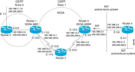
The figure below shows a network diagram in which OSPF Area 1 is defined as the stub area. The Enhanced Interior Gateway Routing Protocol (EIGRP) routes cannot be propagated into the OSPF domain because routing redistribution is not allowed in the stub area. However, once OSPF Area 1 is defined as an NSSA, an NSSA ASBR can inject the EIGRP routes into the OSPF NSSA by creating Type 7 LSAs.
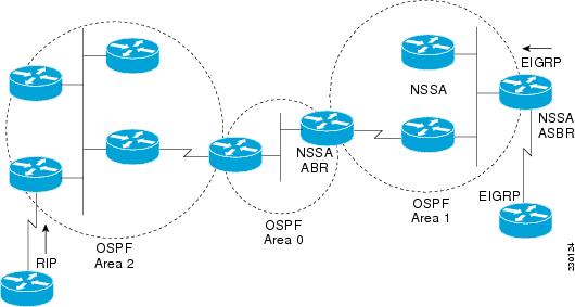
The redistributed routes from the RIP router will not be allowed into OSPF Area 1 because NSSA is an extension to the stub area. The stub area characteristics will still exist, including the exclusion of Type 5 LSAs.
Route summarization is the consolidation of advertised addresses. This feature causes a single summary route to be advertised to other areas by an ABR. In OSPF, an ABR will advertise networks in one area into another area. If the network numbers in an area are assigned in a way such that they are contiguous, you can configure the ABR to advertise a summary route that covers all the individual networks within the area that fall into the specified range.
When routes from other protocols are redistributed into OSPF (as described in the module "Configuring IP Routing Protocol-Independent Features"), each route is advertised individually in an external LSA. However, you can configure the Cisco IOS software to advertise a single route for all the redistributed routes that are covered by a specified network address and mask. Doing so helps decrease the size of the OSPF link-state database.
In OSPF, all areas must be connected to a backbone area. If there is a break in backbone continuity, or the backbone is purposefully partitioned, you can establish a virtual link. The two endpoints of a virtual link are ABRs. The virtual link must be configured in both routers. The configuration information in each router consists of the other virtual endpoint (the other ABR) and the nonbackbone area that the two routers have in common (called the transit area). Note that virtual links cannot be configured through stub areas.
You can force an ASBR to generate a default route into an OSPF routing domain. Whenever you specifically configure redistribution of routes into an OSPF routing domain, the router automatically becomes an ASBR. However, an ASBR does not, by default, generate a default route into the OSPF routing domain.
You can configure OSPF to look up Domain Naming System (DNS) names for use in all OSPF show EXEC command displays. You can use this feature to more easily identify a router, because the router is displayed by name rather than by its router ID or neighbor ID.
OSPF uses the largest IP address configured on the interfaces as its router ID. If the interface associated with this IP address is ever brought down, or if the address is removed, the OSPF process must recalculate a new router ID and resend all its routing information out its interfaces.
If a loopback interface is configured with an IP address, the Cisco IOS software will use this IP address as its router ID, even if other interfaces have larger IP addresses. Because loopback interfaces never go down, greater stability in the routing table is achieved.
OSPF automatically prefers a loopback interface over any other kind, and it chooses the highest IP address among all loopback interfaces. If no loopback interfaces are present, the highest IP address in the router is chosen. You cannot tell OSPF to use any particular interface.
In Cisco IOS Release 10.3 and later releases, by default OSPF calculates the OSPF metric for an interface according to the bandwidth of the interface. For example, a 64-kbps link gets a metric of 1562, and a T1 link gets a metric of 64.
The OSPF metric is calculated as the ref-bw value divided by the bandwidth value, with the ref-bw value equal to 108 by default, and the bandwidth value determined by the bandwidth interface configuration command. The calculation gives FDDI a metric of 1. If you have multiple links with high bandwidth, you might want to specify a larger number to differentiate the cost on those links.
An administrative distance is a rating of the trustworthiness of a routing information source, such as an individual router or a group of routers. Numerically, an administrative distance is an integer from 0 to 255. In general, the higher the value, the lower the trust rating. An administrative distance of 255 means the routing information source cannot be trusted at all and should be ignored.
OSPF uses three different administrative distances: intra-area, interarea, and external. Routes within an area are intra-area; routes to another area are interarea; and routes from another routing domain learned via redistribution are external. The default distance for each type of route is 110.
Because simplex interfaces between two devices on an Ethernet represent only one network segment, for OSPF you must configure the sending interface to be a passive interface. This configuration prevents OSPF from sending hello packets for the sending interface. Both devices are able to see each other via the hello packet generated for the receiving interface.
You can configure the delay time between when OSPF receives a topology change and when it starts a shortest path first (SPF) calculation. You can also configure the hold time between two consecutive SPF calculations.
The OSPF on-demand circuit is an enhancement to the OSPF protocol that allows efficient operation over on-demand circuits such as ISDN, X.25 switched virtual circuits (SVCs), and dialup lines. This feature supports RFC 1793, Extending OSPF to Support Demand Circuits.
Prior to this feature, OSPF periodic hello and LSA updates would be exchanged between routers that connected the on-demand link, even when no changes occurred in the hello or LSA information.
With this feature, periodic hellos are suppressed and the periodic refreshes of LSAs are not flooded over the demand circuit. These packets bring up the link only when they are exchanged for the first time, or when a change occurs in the information they contain. This operation allows the underlying data link layer to be closed when the network topology is stable.
This feature is useful when you want to connect telecommuters or branch offices to an OSPF backbone at a central site. In this case, OSPF for on-demand circuits allows the benefits of OSPF over the entire domain, without excess connection costs. Periodic refreshes of hello updates, LSA updates, and other protocol overhead are prevented from enabling the on-demand circuit when there is no "real" data to send.
Overhead protocols such as hellos and LSAs are transferred over the on-demand circuit only upon initial setup and when they reflect a change in the topology. This means that critical changes to the topology that require new SPF calculations are sent in order to maintain network topology integrity. Periodic refreshes that do not include changes, however, are not sent across the link.
The OSPF LSA group pacing feature allows the router to group OSPF LSAs and pace the refreshing, checksumming, and aging functions. The group pacing results in more efficient use of the router.
The router groups OSPF LSAs and paces the refreshing, checksumming, and aging functions so that sudden increases in CPU usage and network resources are avoided. This feature is most beneficial to large OSPF networks.
OSPF LSA group pacing is enabled by default. For typical customers, the default group pacing interval for refreshing, checksumming, and aging is appropriate and you need not configure this feature.
Original LSA Behavior
Each OSPF LSA has an age, which indicates whether the LSA is still valid. Once the LSA reaches the maximum age (1 hour), it is discarded. During the aging process, the originating router sends a refresh packet every 30 minutes to refresh the LSA. Refresh packets are sent to keep the LSA from expiring, whether there has been a change in the network topology or not. Checksumming is performed on all LSAs every 10 minutes. The router keeps track of LSAs it generates and LSAs it receives from other routers. The router refreshes LSAs it generated; it ages the LSAs it received from other routers.
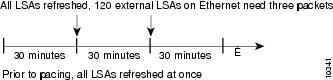
Prior to the LSA group pacing feature, the Cisco IOS software would perform refreshing on a single timer, and checksumming and aging on another timer. In the case of refreshing, for example, the software would scan the whole database every 30 minutes, refreshing every LSA the router generated, no matter how old it was. The figure below illustrates all the LSAs being refreshed at once. This process wasted CPU resources because only a small portion of the database needed to be refreshed. A large OSPF database (several thousand LSAs) could have thousands of LSAs with different ages. Refreshing on a single timer resulted in the age of all LSAs becoming synchronized, which resulted in much CPU processing at once. Furthermore, a large number of LSAs could cause a sudden increase of network traffic, consuming a large amount of network resources in a short period of time.
LSA Group Pacing with Multiple Timers
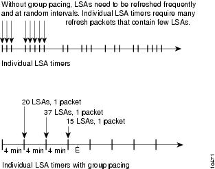
Configuring each LSA to have its own timer avoids excessive CPU processing and sudden network-traffic increase. To again use the example of refreshing, each LSA gets refreshed when it is 30 minutes old, independent of other LSAs. So the CPU is used only when necessary. However, LSAs being refreshed at frequent, random intervals would require many packets for the few refreshed LSAs the router must send out, which would be inefficient use of bandwidth.
Therefore, the router delays the LSA refresh function for an interval of time instead of performing it when the individual timers are reached. The accumulated LSAs constitute a group, which is then refreshed and sent out in one packet or more. Thus, the refresh packets are paced, as are the checksumming and aging. The pacing interval is configurable; it defaults to 4 minutes, which is randomized to further avoid synchronization.
The figure below illustrates the case of refresh packets. The first timeline illustrates individual LSA timers; the second timeline illustrates individual LSA timers with group pacing.
The group pacing interval is inversely proportional to the number of LSAs the router is refreshing, checksumming, and aging. For example, if you have approximately 10,000 LSAs, decreasing the pacing interval would benefit you. If you have a very small database (40 to 100 LSAs), increasing the pacing interval to 10 to 20 minutes might benefit you slightly.
The default value of pacing between LSA groups is 240 seconds (4 minutes). The range is from 10 seconds to 1800 seconds (30 minutes).
By default, OSPF floods new LSAs over all interfaces in the same area, except the interface on which the LSA arrives. Some redundancy is desirable, because it ensures robust flooding. However, too much redundancy can waste bandwidth and might destabilize the network due to excessive link and CPU usage in certain topologies. An example would be a fully meshed topology.
You can block OSPF flooding of LSAs two ways, depending on the type of networks:
- On broadcast, nonbroadcast, and point-to-point networks, you can block flooding over specified OSPF interfaces.
- On point-to-multipoint networks, you can block flooding to a specified neighbor.
The growth of the Internet has increased the importance of scalability in IGPs such as OSPF. By design, OSPF requires LSAs to be refreshed as they expire after 3600 seconds. Some implementations have tried to improve the flooding by reducing the frequency to refresh from 30 minutes to about 50 minutes. This solution reduces the amount of refresh traffic but requires at least one refresh before the LSA expires. The OSPF flooding reduction solution works by reducing unnecessary refreshing and flooding of already known and unchanged information. To achieve this reduction, the LSAs are now flooded with the higher bit set. The LSAs are now set as "do not age."
Cisco routers do not support LSA Type 6 Multicast OSPF (MOSPF), and they generate syslog messages if they receive such packets. If the router is receiving many MOSPF packets, you might want to configure the router to ignore the packets and thus prevent a large number of syslog messages.
The former OSPF implementation for sending update packets needed to be more efficient. Some update packets were getting lost in cases where the link was slow, a neighbor could not receive the updates quickly enough, or the router was out of buffer space. For example, packets might be dropped if either of the following topologies existed:
- A fast router was connected to a slower router over a point-to-point link.
- During flooding, several neighbors sent updates to a single router at the same time.
OSPF update packets are now automatically paced so they are not sent less than 33 milliseconds apart. Pacing is also added between resends to increase efficiency and minimize lost retransmissions. Also, you can display the LSAs waiting to be sent out an interface. The benefit of the pacing is that OSPF update and retransmission packets are sent more efficiently. There are no configuration tasks for this feature; it occurs automatically.
You can display specific statistics such as the contents of IP routing tables, caches, and databases. Information provided can be used to determine resource utilization and solve network problems. You can also display information about node reachability and discover the routing path that your device packets are taking through the network
How to Configure OSPF
To configure OSPF, perform the tasks described in the following sections. The tasks in the Enabling OSPF section are required; the tasks in the remaining sections are optional, but might be required for your application. For information about the maximum number of interfaces, see the Restrictions.
- Enabling OSPF
- Configuring OSPF Interface Parameters
- Configuring OSPF over Different Physical Networks
- Configuring OSPF Area Parameters
- Configuring OSPF NSSA
- Configuring OSPF NSSA Parameters
- Configuring Route Summarization Between OSPF Areas
- Configuring Route Summarization When Redistributing Routes into OSPF
- Establishing Virtual Links
- Generating a Default Route
- Configuring Lookup of DNS Names
- Forcing the Router ID Choice with a Loopback Interface
- Controlling Default Metrics
- Changing the OSPF Administrative Distances
- Configuring OSPF on Simplex Ethernet Interfaces
- Configuring Route Calculation Timers
- Configuring OSPF over On-Demand Circuits
- Logging Neighbors Going Up or Down
- Blocking OSPF LSA Flooding
- Reducing LSA Flooding
- Ignoring MOSPF LSA Packets
- Displaying OSPF Update Packet Pacing
- Monitoring and Maintaining OSPF
- Restrictions
Enabling OSPF
DETAILED STEPS
Configuring OSPF over Different Physical Networks
Configuring Point-to-Multipoint Broadcast Networks
DETAILED STEPS
Configuring OSPF for Nonbroadcast Networks
DETAILED STEPS
| Command or Action | Purpose | |||
|---|---|---|---|---|
Step 1 |
ip
ospf
network
point-to-multipoint
non-broadcast
|
Configures an interface as point-to-multipoint for nonbroadcast media. | ||
Step 2 |
exit
|
Enters global configuration mode. | ||
Step 3 |
router
ospf
process-id
|
Configures an OSPF routing process and enters router configuration mode. | ||
Step 4 | neighbor
ip-address
[cost
number]
|
Specifies a neighbor and assigns a cost to the neighbor.
|
Configuring OSPF NSSA
- Configuring an OSPF NSSA Area and Its Parameters
- Configuring an NSSA ABR as a Forced NSSA LSA Translator
- Disabling RFC 3101 Compatibility and Enabling RFC 1587 Compatibility
Configuring an OSPF NSSA Area and Its Parameters
DETAILED STEPS
| Command or Action | Purpose | |
|---|---|---|
Step 1 |
enable
Example: Router> enable |
Enables privileged EXEC mode.
|
Step 2 |
configure
terminal
Example: Router# configure terminal |
Enters global configuration mode. |
Step 3 |
router
ospf
process-id
Example: Router(config)# router ospf 10 |
Enables OSPF routing and enters router configuration mode. |
Step 4 |
redistribute
protocol
[process-id] {level-1 |
level-1-2 |
level-2} [autonomous-system-number]
[metric {metric-value |
transparent}] [metric-type
type-value] [match {internal |
external
1 |
external
2}] [tag
tag-value] [route-map
map-tag] [subnets] [nssa-only]
Example: Router(config-router)# redistribute rip subnets |
Redistributes routes from one routing domain into another routing domain. |
Step 5 |
network
ip-address
wildcard-mask
area
area-id
Example: Router(config-router)# network 172.19.92.0 0.0.0.255 area 1 |
Defines the interfaces on which OSPF runs and defines the area ID for those interfaces. |
Step 6 |
area
area-id
nssa
[no-redistribution] [default-information-originate [metric] [metric-type]] [no-summary] [nssa-only]
Example: Router(config-router)# area 1 nssa |
Configures an NSSA area. |
Step 7 |
end
Example: Router(config-router)# end |
Exits router configuration mode and returns to privileged EXEC mode. |
Configuring an NSSA ABR as a Forced NSSA LSA Translator
Note | In Cisco IOS Release 15.1(2)S and later releases, the output of the show ip ospf command shows whether the NSSA ABR is configured as a forced translator, and whether the router is running as RFC 3101 or RFC 1587 compatible. |
DETAILED STEPS
| Command or Action | Purpose | |||
|---|---|---|---|---|
Step 1 |
enable
Example: Router> enable |
Enables privileged EXEC mode. | ||
Step 2 |
configure
terminal
Example: Router# configure terminal |
Enters global configuration mode. | ||
Step 3 |
router
ospf
process-id
Example: Router(config)# router ospf 1 |
Enables OSPF routing and enters router configuration mode. | ||
Step 4 |
area
area-id
nssa
translate
type7
always
Example: Router(config-router)# area 10 nssa translate type7 always |
Configures an NSSA ABR router as a forced NSSA LSA translator.
| ||
Step 5 |
end
Example: Router(config-router)# end |
Exits router configuration mode and returns to privileged EXEC mode. |
Disabling RFC 3101 Compatibility and Enabling RFC 1587 Compatibility
Note | In Cisco IOS Release 15.1(2)S and later releases, the output of the show ip ospf command will indicate if the NSSA ABR is configured as RFC 3101 or RFC 1587 compatible. |
DETAILED STEPS
| Command or Action | Purpose | |
|---|---|---|
Step 1 |
enable
Example: Router> enable |
Enables privileged EXEC mode. |
Step 2 |
configure
terminal
Example: Router# configure terminal |
Enters global configuration mode. |
Step 3 |
router
ospf
process-id
Example: Router(config)# router ospf 1 |
Enables OSPF routing and enters router configuration mode. |
Step 4 |
compatible
rfc1587
Example: Router(config-router)# compatible rfc1587 |
Changes the method used to perform route selection to RFC 1587 compatibility and disables RFC 3101. |
Step 5 |
end
Example: Router(config-router)# end |
Exits router configuration mode and returns to privileged EXEC mode. |
Configuring OSPF NSSA Parameters
Prerequisites
Evaluate the following considerations before you implement this feature:
- You can set a Type 7 default route that can be used to reach external destinations. When configured, the router generates a Type 7 default into the NSSA or the NSSA ABR.
- Every router within the same area must agree that the area is NSSA; otherwise, the routers will not be able to communicate.
Generating a Default Route
|
Command |
Purpose |
||
|---|---|---|---|
default-information originate [always] [metric metric-value] [metric-type type-value] [route-map map-name] |
Forces the ASBR to generate a default route into the OSPF routing domain.
|
Forcing the Router ID Choice with a Loopback Interface
DETAILED STEPS
| Command or Action | Purpose | |
|---|---|---|
Step 1 |
interface
loopback
0
|
Creates a loopback interface, which places the router in interface configuration mode. |
Step 2 |
ip
address
ip-address
mask
|
Assigns an IP address to this interface. |
Configuring OSPF over On-Demand Circuits
DETAILED STEPS
| Command or Action | Purpose | |
|---|---|---|
Step 1 |
router ospf
process-id
|
Enables OSPF operation. |
Step 2 |
interface
type number
|
Enters interface configuration mode. |
Step 3 |
ip ospf demand-circuit
|
Configures OSPF over an on-demand circuit. |
Note | You can prevent an interface from accepting demand-circuit requests from other routers to by specifying the ignore keyword in the ip ospf demand-circuit command. |
Prerequisites
Evaluate the following considerations before implementing the On-Demand Circuits feature:
- Because LSAs that include topology changes are flooded over an on-demand circuit, we recommend that you put demand circuits within OSPF stub areas or within NSSAs to isolate the demand circuits from as many topology changes as possible.
- Every router within a stub area or NSSA must have this feature loaded in order to take advantage of the on-demand circuit functionality. If this feature is deployed within a regular area, all other regular areas must also support this feature before the demand circuit functionality can take effect because Type 5 external LSAs are flooded throughout all areas.
- Hub-and-spoke network topologies that have a point-to-multipoint (P2MP) OSPF interface type on a hub might not revert to nondemand circuit mode when needed. You must simultaneously reconfigure OSPF on all interfaces on the P2MP segment when reverting them from demand circuit mode to nondemand circuit mode.
- Do not implement this feature on a broadcast-based network topology because the overhead protocols (such as hello and LSA packets) cannot be successfully suppressed, which means the link will remain up.
- Configuring the router for an OSPF on-demand circuit with an asynchronous interface is not a supported configuration. The supported configuration is to use dialer interfaces on both ends of the circuit. For more information, refer to Why OSPF Demand Circuit Keeps Bringing Up the Link .
Logging Neighbors Going Up or Down
|
Command |
Purpose |
||
|---|---|---|---|
log-adjacency-changes [detail] |
Sends syslog message when an OSPF neighbor goes up or down.
|
Blocking OSPF LSA Flooding
|
Command |
Purpose |
|---|---|
ip ospf database-filter all out
|
Blocks the flooding of OSPF LSA packets to the interface. |
On point-to-multipoint networks, to block flooding of OSPF LSAs, use the following command in router configuration mode:
Monitoring and Maintaining OSPF
|
Command |
Purpose |
|---|---|
show ip ospf [process-id] |
Displays general information about OSPF routing processes. |
show ip ospf border-routers
|
Displays the internal OSPF routing table entries to the ABR and ASBR. |
show ip ospf [process-id
[area-id]] database
show ip ospf [process-id [area-id]] database [database-summary] show ip ospf [process-id [area-id]] database [router] [self-originate] show ip ospf [process-id [area-id]] database [router] [adv-router [ip-address]] show ip ospf [process-id [area-id]] database [router] [link-state-id] show ip ospf [process-id [area-id]] database [network] [link-state-id] show ip ospf [process-id [area-id]] database [summary] [link-state-id] show ip ospf [process-id [area-id]] database [asbr-summary] [link-state-id] show ip ospf [process-id [Router# area-id]] database [external] [link-state-id] show ip ospf [process-id [area-id]] database [nssa-external] [link-state-id] show ip ospf [process-id [area-id]] database [opaque-link] [link-state-id] show ip ospf [process-id [area-id]] database [opaque-area] [link-state-id] show ip ospf [process-id [area-id]] database [opaque-as] [link-state-id] |
Displays lists of information related to the OSPF database. |
show ip ospf flood-list interface type |
Displays a list of LSAs waiting to be flooded over an interface (to observe OSPF packet pacing). |
show ip ospf interface [type number] |
Displays OSPF-related interface information. |
show ip ospf neighbor [interface-name] [neighbor-id] detail |
Displays OSPF neighbor information on a per-interface basis. |
show ip ospf request-list [neighbor] [interface] [interface-neighbor] |
Displays a list of all LSAs requested by a router. |
show ip ospf retransmission-list [neighbor] [interface] [interface-neighbor] |
Displays a list of all LSAs waiting to be re-sent. |
show ip ospf [process-id] summary-address |
Displays a list of all summary address redistribution information configured under an OSPF process. |
show ip ospf virtual-links
|
Displays OSPF-related virtual links information. |
To restart an OSPF process, use the following command in EXEC mode:
Restrictions
On systems with a large number of interfaces, it may be possible to configure OSPF such that the number of links advertised in the router LSA causes the link state update packet to exceed the size of a "huge" Cisco IOS buffer. To resolve this problem, reduce the number of OSPF links or increase the huge buffer size by entering the buffers huge size size command.
A link state update packet containing a router LSA typically has a fixed overhead of 196 bytes, and an additional 12 bytes are required for each link description. With a huge buffer size of 18024 bytes there can be a maximum of 1485 link descriptions.
Because the maximum size of an IP packet is 65,535 bytes, there is still an upper bound on the number of links possible on a router.
Configuration Examples for OSPF
- Example: OSPF Point-to-Multipoint
- Example: OSPF Point-to-Multipoint with Broadcast
- Example: OSPF Point-to-Multipoint with Nonbroadcast
- Example: Variable-Length Subnet Masks
- Example: OSPF NSSA
- Example: OSPF NSSA Area with RFC 3101 Disabled and RFC 1587 Active
- Example: OSPF Routing and Route Redistribution
- Examples: Route Map
- Example: Changing OSPF Administrative Distance
- Example: OSPF over On-Demand Routing
- Example: LSA Group Pacing
- Example: Block LSA Flooding
- Example: Ignore MOSPF LSA Packets
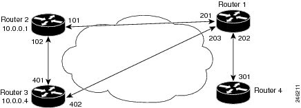
Example: OSPF Point-to-Multipoint
In the figure below, the router named Router 1 uses data-link connection identifier (DLCI) 201 to communicate with the router named Router 2, DLCI 202 to the router named Router 4, and DLCI 203 to the router named Router 3. Router 2 uses DLCI 101 to communicate with Router 1 and DLCI 102 to communicate with Router 3. Router 3 communicates with Router 2 (DLCI 401) and Router 1 (DLCI 402). Router 4 communicates with Router 1 (DLCI 301). Configuration examples follow the figure.
Router 1 Configuration
hostname Router 1
!
interface serial 1
 ip address 10.0.0.2 255.0.0.0
 ip ospf network point-to-multipoint
 encapsulation frame-relay
 frame-relay map ip 10.0.0.1 201 broadcast
 frame-relay map ip 10.0.0.3 202 broadcast
 frame-relay map ip 10.0.0.4 203 broadcast
!
router ospf 1
 network 10.0.0.0 0.0.0.255 area 0
Router 2 Configuration
hostname Router 2
!
interface serial 0
 ip address 10.0.0.1 255.0.0.0
 ip ospf network point-to-multipoint
 encapsulation frame-relay
 frame-relay map ip 10.0.0.2 101 broadcast
 frame-relay map ip 10.0.0.4 102 broadcast
!
router ospf 1
 network 10.0.0.0 0.0.0.255 area 0
Router 3 Configuration
hostname Router 3
!
interface serial 3
 ip address 10.0.0.4 255.0.0.0
 ip ospf network point-to-multipoint
 encapsulation frame-relay
 clock rate 1000000
 frame-relay map ip 10.0.0.1 401 broadcast
 frame-relay map ip 10.0.0.2 402 broadcast
!
router ospf 1
 network 10.0.0.0 0.0.0.255 area 0
Example: OSPF Point-to-Multipoint with Broadcast
The following example illustrates a point-to-multipoint network with broadcast:
interface Serial0
 ip address 10.0.1.1 255.255.255.0
 encapsulation frame-relay
 ip ospf cost 100
 ip ospf network point-to-multipoint
 frame-relay map ip 10.0.1.3 202 broadcast
 frame-relay map ip 10.0.1.4 203 broadcast
 frame-relay map ip 10.0.1.5 204 broadcast
 frame-relay local-dlci 200
!
router ospf 1
 network 10.0.1.0 0.0.0.255 area 0
 neighbor 10.0.1.5 cost 5
 neighbor 10.0.1.4 cost 10
The following example shows the configuration of the neighbor at 10.0.1.3:
interface serial 0
 ip address 10.0.1.3 255.255.255.0
 ip ospf network point-to-multipoint
 encapsulation frame-relay
 frame-relay local-dlci 301
 frame-relay map ip 10.0.1.1 300 broadcast
 no shutdown
!
 router ospf 1
 network 10.0.1.0 0.0.0.255 area 0
The output shown for neighbors in the first configuration is as follows:
Router# show ip ospf neighbor
Neighbor ID     Pri   State           Dead Time   Address         Interface
172.16.1.1           1   FULL/  -        00:01:50    10.0.1.5        Serial0
172.16.1.4           1   FULL/  -        00:01:47    10.0.1.4        Serial0
172.16.1.8           1   FULL/  -        00:01:45    10.0.1.3        Serial0
The route information in the first configuration is as follows:
Router# show ip route
Codes: C - connected, S - static, I - IGRP, R - RIP, M - mobile, B - BGP
       D - EIGRP, EX - EIGRP external, O - OSPF, IA - OSPF inter area
       N1 - OSPF NSSA external type 1, N2 - OSPF NSSA external type 2
       E1 - OSPF external type 1, E2 - OSPF external type 2, E - EGP
       i - IS-IS, L1 - IS-IS level-1, L2 - IS-IS level-2, * - candidate default
       U - per-user static route, o - ODR
Gateway of last resort is not set
C    1.0.0.0/8 is directly connected, Loopback0
     10.0.0.0/8 is variably subnetted, 4 subnets, 2 masks
O       10.0.1.3/32 [110/100] via 10.0.1.3, 00:39:08, Serial0
C       10.0.1.0/24 is directly connected, Serial0
O       10.0.1.5/32 [110/5] via 10.0.1.5, 00:39:08, Serial0
O       10.0.1.4/32 [110/10] via 10.0.1.4, 00:39:08, Serial0
Example: OSPF Point-to-Multipoint with Nonbroadcast
The following example illustrates a point-to-multipoint network with nonbroadcast:
interface Serial0
ip address 10.0.1.1 255.255.255.0
ip ospf network point-to-multipoint non-broadcast
encapsulation frame-relay
no keepalive
frame-relay local-dlci 200
frame-relay map ip 10.0.1.3 202
frame-relay map ip 10.0.1.4 203
frame-relay map ip 10.0.1.5 204
no shutdown
!
router ospf 1
network 10.0.1.0 0.0.0.255 area 0
neighbor 10.0.1.3 cost 5
neighbor 10.0.1.4 cost 10
neighbor 10.0.1.5 cost 15
The following example is the configuration for the router on the other side:
interface Serial9/2
 ip address 10.0.1.3 255.255.255.0
 encapsulation frame-relay
 ip ospf network point-to-multipoint non-broadcast
 no ip mroute-cache
 no keepalive
 no fair-queue
 frame-relay local-dlci 301
 frame-relay map ip 10.0.1.1 300
 no shutdown
 !
 router ospf 1
 network 10.0.1.0 0.0.0.255 area 0
The output shown for neighbors in the first configuration is as follows:
Router# show ip ospf neighbor
Neighbor ID     Pri   State           Dead Time   Address         Interface
172.16.1.1           1   FULL/  -        00:01:52    10.0.1.5        Serial0
172.16.1.4           1   FULL/  -        00:01:52    10.0.1.4        Serial0
172.16.1.8           1   FULL/  -        00:01:52    10.0.1.3        Serial0
Example: Variable-Length Subnet Masks
OSPF, static routes, and IS-IS support variable-length subnet masks (VLSMs). With VLSMs, you can use different masks for the same network number on different interfaces, which allows you to conserve IP addresses and more efficiently use available address space.
In the following example, a 30-bit subnet mask is used, leaving two bits of address space reserved for serial line host addresses. There is sufficient host address space for two host endpoints on a point-to-point serial link.
interface ethernet 0
 ip address 172.16.10.1 255.255.255.0
! 8 bits of host address space reserved for ethernets
interface serial 0
 ip address 172.16.20.1 255.255.255.252
! 2 bits of address space reserved for serial lines
! Router is configured for OSPF and assigned AS 107
router ospf 107
! Specifies network directly connected to the router
 network 172.16.0.0 0.0.255.255 area 0.0.0.0
Example: OSPF NSSA
In the following example, an OSPF stub network is configured to include OSPF Area 0 and OSPF Area 1, using five routers. OSPF Area 1 is defined as an NSSA, with Router 3 configured to be the NSSA ASBR and Router 2 configured to be the NSSA ABR. Following is the configuration output for the five routers.
Router 1
hostname Router1
!
interface Loopback1
 ip address 10.1.0.1 255.255.255.255
!
interface Ethernet0/0
 ip address 192.168.0.1 255.255.255.0
 ip ospf 1 area 0
 no cdp enable
!
interface Serial10/0
 description Router2 interface s11/0
 ip address 192.168.10.1 255.255.255.0
 ip ospf 1 area 1
 serial restart-delay 0
 no cdp enable
!
router ospf 1
 area 1 nssa
!
end
Router 2
hostname Router2
!
!
interface Loopback1
 ip address 10.1.0.2 255.255.255.255
!
interface Serial10/0
 description Router1 interface s11/0
 no ip address
 shutdown
 serial restart-delay 0
 no cdp enable
!
interface Serial11/0
 description Router1 interface s10/0
 ip address 192.168.10.2 255.255.255.0
 ip ospf 1 area 1
 serial restart-delay 0
 no cdp enable
!
interface Serial14/0
 description Router3 interface s13/0
 ip address 192.168.14.2 255.255.255.0
 ip ospf 1 area 1
 serial restart-delay 0
 no cdp enable
!
router ospf 1
 area 1 nssa
!
end
Router 3
hostname Router3
!
interface Loopback1
 ip address 10.1.0.3 255.255.255.255
!
interface Ethernet3/0
 ip address 192.168.3.3 255.255.255.0
 no cdp enable
!
interface Serial13/0
 description Router2 interface s14/0
 ip address 192.168.14.3 255.255.255.0
 ip ospf 1 area 1
 serial restart-delay 0
 no cdp enable
!
router ospf 1
 log-adjacency-changes
 area 1 nssa
 redistribute rip subnets
!
router rip
 version 2
 redistribute ospf 1 metric 15
 network 192.168.3.0
end
Router 4
hostname Router4
!
interface Loopback1
 ip address 10.1.0.4 255.255.255.255
!
interface Ethernet3/0
 ip address 192.168.3.4 255.255.255.0
 no cdp enable
!
interface Ethernet4/1
 ip address 192.168.41.4 255.255.255.0
!
router rip
 version 2
 network 192.168.3.0
 network 192.168.41.0
!
end
Router 5
hostname Router5
!
interface Loopback1
 ip address 10.1.0.5 255.255.255.255
!
interface Ethernet0/0
 ip address 192.168.0.10 255.255.255.0
 ip ospf 1 area 0
 no cdp enable
!
interface Ethernet1/1
 ip address 192.168.11.10 255.255.255.0
 ip ospf 1 area 0
!
router ospf 1
!
end
The figure below shows the OSPF stub network with NSSA Area 1. The redistributed routes that Router 4 is propagating from the two RIP networks will be translated into Type 7 LSAs by NSSA ASBR Router 3. Router 2, which is configured to be the NSSA ABR, will translate the Type 7 LSAs back to Type 5 so that they can be flooded through the rest of the OSPF stub network within OSPF Area 0.
When the show ip ospf command is entered on Router 2, the output confirms that OSFP Area 1 is an NSSA area:
Router2# show ip ospf
 Routing Process "ospf 1" with ID 10.1.0.2
 Start time: 00:00:01.392, Time elapsed: 12:03:09.480
 Supports only single TOS(TOS0) routes
 Supports opaque LSA
 Supports Link-local Signaling (LLS)
 Supports area transit capability
 Router is not originating router-LSAs with maximum metric
 Initial SPF schedule delay 5000 msecs
 Minimum hold time between two consecutive SPFs 10000 msecs
 Maximum wait time between two consecutive SPFs 10000 msecs
 Incremental-SPF disabled
 Minimum LSA interval 5 secs
 Minimum LSA arrival 1000 msecs
 LSA group pacing timer 240 secs
 Interface flood pacing timer 33 msecs
 Retransmission pacing timer 66 msecs
 Number of external LSA 0. Checksum Sum 0x000000
 Number of opaque AS LSA 0. Checksum Sum 0x000000
 Number of DCbitless external and opaque AS LSA 0
 Number of DoNotAge external and opaque AS LSA 0
 Number of areas in this router is 1. 0 normal 0 stub 1 nssa
 Number of areas transit capable is 0
 External flood list length 0
    Area 1
  Number of interfaces in this area is 2
! It is a NSSA area
  Area has no authentication
  SPF algorithm last executed 11:37:58.836 ago
  SPF algorithm executed 3 times
  Area ranges are
  Number of LSA 7. Checksum Sum 0x045598
  Number of opaque link LSA 0. Checksum Sum 0x000000
  Number of DCbitless LSA 0
  Number of indication LSA 0
  Number of DoNotAge LSA 0
  Flood list length 0

Router2# show ip ospf data
            OSPF Router with ID (10.1.0.2) (Process ID 1)
		Router Link States (Area 1)
Link ID         ADV Router      Age         Seq#       Checksum Link count
10.1.0.1        10.1.0.1        1990        0x80000016 0x00CBCB 2
10.1.0.2        10.1.0.2        1753        0x80000016 0x009371 4
10.1.0.3        10.1.0.3        1903        0x80000016 0x004149 2
		Summary Net Link States (Area 1)
Link ID         ADV Router      Age         Seq#       Checksum
192.168.0.0     10.1.0.1        1990        0x80000017 0x00A605
192.168.11.0    10.1.0.1        1990        0x80000015 0x009503
		Type-7 AS External Link States (Area 1)
Link ID         ADV Router      Age         Seq#       Checksum Tag
192.168.3.0     10.1.0.3        1903        0x80000015 0x00484F 0
192.168.41.0    10.1.0.3        1903        0x80000015 0x00A4CC 0
Entering the show ip ospf database data command displays additional information about redistribution between Type 5 and Type 7 LSAs for routes that have been injected into the NSSA area and then flooded through the OSPF network.
Router2# show ip ospf database data
            OSPF Router with ID (10.1.0.2) (Process ID 1)
Area 1 database summary
  LSA Type      Count    Delete   Maxage
  Router        3        0        0
  Network       0        0        0
  Summary Net   2        0        0
  Summary ASBR  0        0        0
  Type-7 Ext    2        0        0
     Prefixes redistributed in Type-7  0
  Opaque Link   0        0        0
  Opaque Area   0        0        0
  Subtotal      7        0        0
Process 1 database summary
  LSA Type      Count    Delete   Maxage
  Router        3        0        0
  Network       0        0        0
  Summary Net   2        0        0
  Summary ASBR  0        0        0
  Type-7 Ext    2        0        0
  Opaque Link   0        0        0
  Opaque Area   0        0        0
  Type-5 Ext    0        0        0
      Prefixes redistributed in Type-5  0
  Opaque AS     0        0        0
  Total         7        0        0
Entering the show ip ospf database nssa command also displays detailed information for Type 7 to Type 5 translations:
Router2# show ip ospf database nssa
            OSPF Router with ID (10.1.0.2) (Process ID 1)
      Type-7 AS External Link States (Area 1)
  Routing Bit Set on this LSA
  LS age: 1903
  Options: (No TOS-capability, Type 7/5 translation, DC)
  LS Type: AS External Link
  Link State ID: 192.168.3.0 (External Network Number )
  Advertising Router: 10.1.0.3
  LS Seq Number: 80000015
  Checksum: 0x484F
  Length: 36
  Network Mask: /24
  Metric Type: 2 (Larger than any link state path)
  TOS: 0
  Metric: 20
  Forward Address: 192.168.14.3
  External Route Tag: 0
  Routing Bit Set on this LSA
  LS age: 1903
! Options: (No TOS-capability, Type 7/5 translation, DC)
  LS Type: AS External Link
  Link State ID: 192.168.41.0 (External Network Number )
  Advertising Router: 10.1.0.3
  LS Seq Number: 80000015
  Checksum: 0xA4CC
  Length: 36
  Network Mask: /24
  Metric Type: 2 (Larger than any link state path)
  TOS: 0
  Metric: 20
  Forward Address: 192.168.14.3
  External Route Tag: 0
Router 3
Entering the show ip ospf command on Router 3 displays the information to confirm that Router 3 is acting as an ASBR and that OSPF Area 1 has been configured to be an NSSA area:
Router3# show ip ospf
 Routing Process "ospf 1" with ID 10.1.0.3
 Start time: 00:00:01.392, Time elapsed: 12:02:34.572
 Supports only single TOS(TOS0) routes
 Supports opaque LSA
 Supports Link-local Signaling (LLS)
 Supports area transit capability
!It is an autonomous system boundary router
 Redistributing External Routes from,
    rip, includes subnets in redistribution
 Router is not originating router-LSAs with maximum metric
 Initial SPF schedule delay 5000 msecs
 Minimum hold time between two consecutive SPFs 10000 msecs
 Maximum wait time between two consecutive SPFs 10000 msecs
 Incremental-SPF disabled
 Minimum LSA interval 5 secs
 Minimum LSA arrival 1000 msecs
 LSA group pacing timer 240 secs
 Interface flood pacing timer 33 msecs
 Retransmission pacing timer 66 msecs
 Number of external LSA 0. Checksum Sum 0x000000
 Number of opaque AS LSA 0. Checksum Sum 0x000000
 Number of DCbitless external and opaque AS LSA 0
 Number of DoNotAge external and opaque AS LSA 0
 Number of areas in this router is 1. 0 normal 0 stub 1 nssa
 Number of areas transit capable is 0
 External flood list length 0
    Area 1
  Number of interfaces in this area is 1
! It is a NSSA area
  Area has no authentication
  SPF algorithm last executed 11:38:13.368 ago
  SPF algorithm executed 3 times
  Area ranges are
  Number of LSA 7. Checksum Sum 0x050CF7
  Number of opaque link LSA 0. Checksum Sum 0x000000
  Number of DCbitless LSA 0
  Number of indication LSA 0
  Number of DoNotAge LSA 0
  Flood list length 0
Example: OSPF NSSA Area with RFC 3101 Disabled and RFC 1587 Active
In the following example, the output for the show ip ospf and show ip ospf database nssa commands is for an OSPF NSSA area where RFC 3101 is disabled, RFC 1587 is active, and an NSSA ABR router is configured as a forced NSSA LSA translator. As described in the "Configuring OSPF NSSA", if RFC 3101 is disabled, the forced NSSA LSA translator remains inactive. The command output demonstrates this.
Router# show ip ospf
Routing Process "ospf 1" with ID 10.0.2.1
Start time: 00:00:25.512, Time elapsed: 00:01:02.200
Supports only single TOS(TOS0) routes
Supports opaque LSA
Supports Link-local Signaling (LLS)
Supports area transit capability
Supports NSSA (compatible with RFC 1587)
Event-log enabled, Maximum number of events: 1000, Mode: cyclic
Router is not originating router-LSAs with maximum metric
Initial SPF schedule delay 5000 msecs
Minimum hold time between two consecutive SPFs 10000 msecs
Maximum wait time between two consecutive SPFs 10000 msecs
Incremental-SPF disabled
Minimum LSA interval 5 secs
Minimum LSA arrival 1000 msecs
LSA group pacing timer 240 secs
Interface flood pacing timer 33 msecs
Retransmission pacing timer 66 msecs
Number of external LSA 0. Checksum Sum 0x000000
Number of opaque AS LSA 0. Checksum Sum 0x000000
Number of DCbitless external and opaque AS LSA 0
Number of DoNotAge external and opaque AS LSA 0
Number of areas in this router is 1. 0 normal 0 stub 1 nssa
Number of areas transit capable is 0
External flood list length 0
IETF NSF helper support enabled
Cisco NSF helper support enabled
Reference bandwidth unit is 100 mbps
Area 1
Number of interfaces in this area is 1
It is a NSSA area
Configured to translate Type-7 LSAs, inactive (RFC3101 support
disabled)
Area has no authentication
SPF algorithm last executed 00:00:07.160 ago
SPF algorithm executed 3 times
Area ranges are
Number of LSA 3. Checksum Sum 0x0245F0
Number of opaque link LSA 0. Checksum Sum 0x000000
Number of DCbitless LSA 0
Number of indication LSA 0
Number of DoNotAge LSA 0
Flood list length 0
The "Supports NSSA (compatible with RFC 1587)" line in the output indicates that RFC 1587 is active or that the OSPF NSSA area is RFC 1587 compatible.
The "Configured to translate Type-7 LSAs, inactive (RFC3101 support disabled)" line indicates that the OSPF NSSA area has an ABR router configured to act as a forced translator of Type 7 LSAs, but it is inactive because RFC 3101 is disabled.
Router2# show ip ospf database nssa
Router Link States (Area 1)
LS age: 28
Options: (No TOS-capability, DC)
LS Type: Router Links
Link State ID: 10.0.2.1
Advertising Router: 10.0.2.1
LS Seq Number: 80000004
Checksum: 0x5CA2
Length: 36
Area Border Router
AS Boundary Router
Unconditional NSSA translator
Number of Links: 1
Link connected to: a Stub Network
(Link ID) Network/subnet number: 192.0.2.5
(Link Data) Network Mask: 255.255.255.0
Number of MTID metrics: 0
TOS 0 Metrics: 10
The "Unconditional NSSA translator" line indicates that the status of the NSSA ASBR router is as a forced NSSA LSA translator.
Example: OSPF Routing and Route Redistribution
OSPF typically requires coordination among many internal routers, ABRs, and ASBRs. At a minimum, OSPF-based routers can be configured with all default parameter values, with no authentication, and with interfaces assigned to areas.
Three types of examples follow:
- The first is a simple configuration illustrating basic OSPF commands.
- The second example illustrates a configuration for an internal router, ABR, and ASBRs within a single, arbitrarily assigned, OSPF autonomous system.
- The third example illustrates a more complex configuration and the application of various tools available for controlling OSPF-based routing environments.
- Example: Basic OSPF Configuration
- Example: Basic OSPF Configuration for Internal Router ABR and ASBRs
- Example: Complex Internal Router with ABR and ASBR
- Example: Complex OSPF Configuration for ABR
Example: Basic OSPF Configuration
The following example illustrates a simple OSPF configuration that enables OSPF routing process 9000, attaches Ethernet interface 0 to area 0.0.0.0, and redistributes RIP into OSPF, and OSPF into RIP:
interface ethernet 0
 ip address 10.93.1.1 255.255.255.0
 ip ospf cost 1
!
interface ethernet 1
 ip address 10.94.1.1 255.255.255.0
!
router ospf 9000
 network 10.93.0.0 0.0.255.255 area 0.0.0.0
 redistribute rip metric 1 subnets
!
router rip
 network 10.94.0.0
 redistribute ospf 9000
 default-metric 1
Example: Basic OSPF Configuration for Internal Router ABR and ASBRs
The following example illustrates the assignment of four area IDs to four IP address ranges. In the example, OSPF routing process 109 is initialized, and four OSPF areas are defined: 10.9.50.0, 2, 3, and 0. Areas 10.9.50.0, 2, and 3 mask specific address ranges, and area 0 enables OSPF for all other networks.
router ospf 109
 network 192.168.10.0 0.0.0.255 area 10.9.50.0
 network 192.168.20.0 0.0.255.255 area 2
 network 192.168.30.0 0.0.0.255 area 3
 network 192.168.40.0 255.255.255.255 area 0
!
! Interface Ethernet0 is in area 10.9.50.0:
interface ethernet 0
 ip address 192.168.10.5 255.255.255.0
!
! Interface Ethernet1 is in area 2:
interface ethernet 1
 ip address 192.168.20.5 255.255.255.0
!
! Interface Ethernet2 is in area 2:
interface ethernet 2
 ip address 192.168.20.7 255.255.255.0
!
! Interface Ethernet3 is in area 3:
interface ethernet 3
 ip address 192.169.30.5 255.255.255.0
!
! Interface Ethernet4 is in area 0:
interface ethernet 4
 ip address 192.168.40.1 255.255.255.0
!
! Interface Ethernet5 is in area 0:
interface ethernet 5
 ip address 192.168.40.12 255.255.0.0
Each network area router configuration command is evaluated sequentially, so the order of these commands in the configuration is important. The Cisco IOS software sequentially evaluates the address/wildcard-mask pair for each interface. See the network area command in the Cisco IOS IP Routing: OSPF Command Reference for more information.
Consider the first network area command. Area ID 10.9.50.0 is configured for the interface on which subnet 192.168.10.0 is located. Assume that a match is determined for Ethernet interface 0. Ethernet interface 0 is attached to area 10.9.50.0 only.
The second network area command is evaluated next. For area 2, the same process is then applied to all interfaces (except Ethernet interface 0). Assume that a match is determined for interface Ethernet 1. OSPF is then enabled for that interface and Ethernet interface 1 is attached to area 2.
This process of attaching interfaces to OSPF areas continues for all network area commands. Note that the last network area command in this example is a special case. With this command, all available interfaces (not explicitly attached to another area) are attached to area 0.
Example: Complex Internal Router with ABR and ASBR
The following example outlines a configuration for several routers within a single OSPF autonomous system. The figure below provides a general network map that illustrates this example configuration.
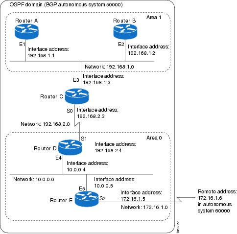
In this configuration, five routers are configured with OSPF:
- Router A and Router Bare both internal routers within area 1.
- Router C is an OSPF ABR. Note that for Router C, Area 1 is assigned to E3 and area 0 is assigned to S0.
- Router D is an internal router in area 0 (backbone area). In this case, both network router configuration commands specify the same area (area 0, or the backbone area).
- Router E is an OSPF ASBR. Note that BGP routes are redistributed into OSPF and that these routes are advertised by OSPF.
Note | You do not need to include definitions of all areas in an OSPF autonomous system in the configuration of all routers in the autonomous system. Only the directly connected areas must be defined. In the example that follows, routes in area 0 are learned by the routers in area 1 (Router A and Router B) when the ABR (Router C) injects summary LSAs into area 1. |
The OSPF domain in BGP autonomous system 109 is connected to the outside world via the BGP link to the external peer at IP address 10.0.0.6. Example configurations follow.
Following is the sample configuration for the general network map shown in the figure above.
Router A Configuration--Internal Router
interface ethernet 1
 ip address 192.168.1.1 255.255.255.0
router ospf 1
 network 192.168.0.0 0.0.255.255 area 1
Router B Configuration--Internal Router
interface ethernet 2
 ip address 192.168.1.2 255.255.255.0
router ospf 202
 network 192.168.0.0 0.0.255.255 area 1
Router C Configuration--ABR
interface ethernet 3
 ip address 192.168.1.3 255.255.255.0
interface serial 0
 ip address 192.168.2.3 255.255.255.0
router ospf 999
 network 192.168.1.0 0.0.0.255 area 1
 network 192.168.2.0 0.0.0.255 area 0
Router D Configuration--Internal Router
interface ethernet 4
 ip address 10.0.0.4 255.0.0.0
interface serial 1
 ip address 192.168.2.4 255.255.255.0
router ospf 50
 network 192.168.2.0 0.0.0.255 area 0
 network 10.0.0.0 0.255.255.255 area 0
Router E Configuration--ASBR
interface ethernet 5
 ip address 10.0.0.5 255.0.0.0
interface serial 2
 ip address 172.16.1.5 255.255.255.0
router ospf 65001
 network 10.0.0.0 0.255.255.255 area 0
 redistribute bgp 109 metric 1 metric-type 1
router bgp 109
 network 192.168.0.0
 network 10.0.0.0
 neighbor 172.16.1.6 remote-as 110
Example: Complex OSPF Configuration for ABR
The following example configuration accomplishes several tasks in setting up an ABR. These tasks can be split into two general categories:
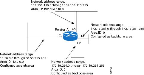
The specific tasks outlined in this configuration are detailed briefly in the following descriptions. The figure below illustrates the network address ranges and area assignments for the interfaces.
The basic configuration tasks in this example are as follows:
- Configure address ranges for Ethernet interface 0 through Ethernet interface 3.
- Enable OSPF on each interface.
- Set up an OSPF authentication password for each area and network.
- Assign link-state metrics and other OSPF interface configuration options.
- Create a stub area with area ID 36.0.0.0. (Note that the authentication and stub options of the area router configuration command are specified with separate area command entries, but can be merged into a single area command.)
- Specify the backbone area (area 0).
Configuration tasks associated with redistribution are as follows:
- Redistribute IGRP and RIP into OSPF with various options set (including including metric-type, metric, tag, and subnet).
- Redistribute IGRP and OSPF into RIP.
The following is an example OSPF configuration:
interface ethernet 0
 ip address 192.42.110.201 255.255.255.0
 ip ospf authentication-key abcdefgh
 ip ospf cost 10
!
interface ethernet 1
 ip address 172.19.251.202 255.255.255.0
 ip ospf authentication-key ijklmnop
 ip ospf cost 20
 ip ospf retransmit-interval 10
 ip ospf transmit-delay 2
 ip ospf priority 4
!
interface ethernet 2
 ip address 172.19.254.2 255.255.255.0
 ip ospf authentication-key abcdefgh
 ip ospf cost 10
!
interface ethernet 3
 ip address 10.56.0.0 255.255.0.0
 ip ospf authentication-key ijklmnop
 ip ospf cost 20
 ip ospf dead-interval 80
In the following configuration OSPF is on network 172.16.0.0:
router ospf 201
 network 10.10.0.0 0.255.255.255 area 10.10.0.0
 network 192.42.110.0 0.0.0.255 area 192.42.110.0
 network 172.16.0.0 0.0.255.255 area 0
 area 0 authentication
 area 10.10.0.0 stub
 area 10.10.0.0 authentication
 area 10.10.0.0 default-cost 20
 area 192.42.110.0 authentication
 area 10.10.0.0 range 10.10.0.0 255.0.0.0
 area 192.42.110.0 range 192.42.110.0 255.255.255.0
 area 0 range 172.16.251.0 255.255.255.0
 area 0 range 172.16.254.0 255.255.255.0
 redistribute igrp 200 metric-type 2 metric 1 tag 200 subnets
 redistribute rip metric-type 2 metric 1 tag 200
In the following configuration, IGRP autonomous system 200 is on 192.0.2.1:
router igrp 200
 network 172.31.0.0
!
! RIP for 192.168.110
!
router rip
 network 192.168.110.0
 redistribute igrp 200 metric 1
 redistribute ospf 201 metric 1
Examples: Route Map
The examples in this section illustrate the use of redistribution, with and without route maps. Examples from both the IP and Connectionless Network Service (CLNS) routing protocols are given.
The following example redistributes all OSPF routes into IGRP:
router igrp 109
 redistribute ospf 110
The following example redistributes RIP routes with a hop count equal to 1 into OSPF. These routes will be redistributed into OSPF as external LSAs with a metric of 5, a metric type of Type 1, and a tag equal to 1.
router ospf 109
 redistribute rip route-map rip-to-ospf
!
route-map rip-to-ospf permit
 match metric 1
 set metric 5
 set metric-type type1
 set tag 1
The following example redistributes OSPF learned routes with tag 7 as a RIP metric of 15:
router rip
 redistribute ospf 109 route-map 5
!
route-map 5 permit
 match tag 7
 set metric 15
The following example redistributes OSPF intra-area and interarea routes with next hop routers on serial interface 0 into BGP with an INTER_AS metric of 5:
router bgp 109
 redistribute ospf 109 route-map 10
!
route-map 10 permit
 match route-type internal
 match interface serial 0
 set metric 5
The following example redistributes two types of routes into the integrated IS-IS routing table (supporting both IP and CLNS). The first type is OSPF external IP routes with tag 5; these routes are inserted into Level 2 IS-IS link state packets (LSPs) with a metric of 5. The second type is ISO-IGRP derived CLNS prefix routes that match CLNS access list 2000; these routes will be redistributed into IS-IS as Level 2 LSPs with a metric of 30.
router isis
 redistribute ospf 109 route-map 2
 redistribute iso-igrp nsfnet route-map 3
!
route-map 2 permit
 match route-type external
 match tag 5
 set metric 5
 set level level-2
!
route-map 3 permit
 match address 2000
 set metric 30
With the following configuration, OSPF external routes with tags 1, 2, 3, and 5 are redistributed into RIP with metrics of 1, 1, 5, and 5, respectively. The OSPF routes with a tag of 4 are not redistributed.
router rip
 redistribute ospf 109 route-map 1
!
route-map 1 permit
 match tag 1 2
 set metric 1
!
route-map 1 permit
 match tag 3
 set metric 5
!
route-map 1 deny
 match tag 4
!
route map 1 permit
 match tag 5
 set metric 5
In the following configuration, a RIP learned route for network 160.89.0.0 and an ISO-IGRP learned route with prefix 49.0001.0002 will be redistributed into an IS-IS Level 2 LSP with a metric of 5:
router isis
 redistribute rip route-map 1
 redistribute iso-igrp remote route-map 1
!
route-map 1 permit
 match ip address 1
 match clns address 2
 set metric 5
 set level level-2
!
 access-list 1 permit 192.168.0.0 0.0.255.255
 clns filter-set 2 permit 49.0001.0002...
The following configuration example illustrates how a route map is referenced by the default-information router configuration command. This type of reference is called conditional default origination. OSPF will originate the default route (network 0.0.0.0) with a Type 2 metric of 5 if 140.222.0.0 is in the routing table.
Note | Only routes external to the OSPF process can be used for tracking, such as non-OSPF routes or OSPF routes from a separate OSPF process. |
route-map ospf-default permit
 match ip address 1
 set metric 5
 set metric-type type-2
!
 access-list 1 permit 172.16.0.0 0.0.255.255
!
router ospf 109
 default-information originate route-map ospf-default
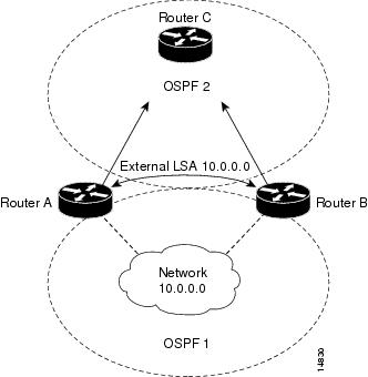
Example: Changing OSPF Administrative Distance
The following configuration changes the external distance to 200, making it less trustworthy. The figure below illustrates the example.
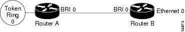
Example: OSPF over On-Demand Routing
The following configuration allows OSPF over an on-demand circuit, as shown in the figure below. Note that the on-demand circuit is defined on one side only (BRI 0 on Router A); it is not required to be configured on both sides.
Router A Configuration
username RouterB password 7 060C1A2F47
isdn switch-type basic-5ess
ip routing
!
interface TokenRing0
 ip address 192.168.50.5 255.255.255.0
 no shutdown
!
interface BRI0
 no cdp enable
 description connected PBX 1485
 ip address 192.168.45.30 255.255.255.0
 encapsulation ppp
 ip ospf demand-circuit
 dialer map ip 140.10.10.6 name RouterB broadcast 61484
 dialer-group 1
 ppp authentication chap
 no shutdown
!
router ospf 100
 network 192.168.45.0 0.0.0.255 area 0
 network 192.168.45.50 0.0.0.255 area 0
!
dialer-list 1 protocol ip permit
Router B Configuration
username RouterA password 7 04511E0804
isdn switch-type basic-5ess
ip routing
!
interface Ethernet0
 ip address 192.168.50.16 255.255.255.0
 no shutdown
!
interface BRI0
 no cdp enable
 description connected PBX 1484
 ip address  192.168.45.17 255.255.255.0
 encapsulation ppp
 dialer map ip 192.168.45.19 name RouterA broadcast 61485
 dialer-group 1
 ppp authentication chap
 no shutdown
!
router ospf 100
 network 192.168.45.0 0.0.0.255 area 0
 network 192.168.45.50 0.0.0.255 area 0
!
dialer-list 1 protocol ip permit
Example: Block LSA Flooding
The following example prevents flooding of OSPF LSAs to broadcast, nonbroadcast, or point-to-point networks reachable through Ethernet interface 0:
interface ethernet 0
 ip ospf database-filter all out
The following example prevents flooding of OSPF LSAs to point-to-multipoint networks to the neighbor at IP address 10.10.10.45:
router ospf 109
 neighbor 10.10.10.45 database-filter all out
Additional References
Related Documents
MIBs
RFCs
|
RFC |
Title |
|---|---|
|
RFC 1253 |
OSPF Version 2 Management Information Base, August 1991. |
|
RFC 1587 |
The OSPF NSSA Option , March 1994 |
|
RFC 1793 |
Extending OSPF to Support Demand Circuits , April 1995 |
|
RFC 2328 |
OSPF Version 2, April 1998 |
|
RFC 3101 |
Technical Assistance
|
Description |
Link |
|---|---|
|
The Cisco Support and Documentation website provides online resources to download documentation, software, and tools. Use these resources to install and configure the software and to troubleshoot and resolve technical issues with Cisco products and technologies. Access to most tools on the Cisco Support and Documentation website requires a Cisco.com user ID and password. |
Feature Information for Configuring OSPF
The following table provides release information about the feature or features described in this module. This table lists only the software release that introduced support for a given feature in a given software release train. Unless noted otherwise, subsequent releases of that software release train also support that feature.
Use Cisco Feature Navigator to find information about platform support and Cisco software image support. To access Cisco Feature Navigator, go to www.cisco.com/go/cfn. An account on Cisco.com is not required.
| Table 1 | Feature Information for OSPF |
|
Feature Name |
Releases |
Feature Information |
|---|---|---|
|
OSPF |
11.2.1 |
OSPF is an IGP developed by the OSPF working group of the IETF. Designed expressly for IP networks, OSPF supports IP subnetting and tagging of externally derived routing information. OSPF also allows packet authentication and uses IP multicast when sending and receiving packets. |
|
OSPF Flooding Reduction |
12.1(2)T |
The OSPF flooding reduction solution works by reducing unnecessary refreshing and flooding of already known and unchanged information. This feature is documented in the following section: |
|
OSPF Not-So-Stubby Areas |
11.2.1 |
OSPF NSSA is a nonproprietary extension of the existing OSPF stub area feature. This feature is documented in the following sections: |
|
OSPF Packet Pacing |
12.0(1)T |
OSPF update packets are automatically paced so they are not sent less than 33 milliseconds apart. This feature is documented in the following section: |
|
OSPF Support for NSSA RFC 3101 |
15.1(2)S 15.0(1)SY 15.2(2)T |
This feature adds support for the OSPF NSSA specification described by RFC 3101. RFC3101 replaced RFC 1587 and is backward compatible with RFC1587. The following commands were introduced or modified: area nssa translate, compatible rfc1587. |
|
OSPF - Demand Circuit Disable |
15.0(1)SY |
The ignore keyword was added to the ip ospf demand-circuit command, allowing you to prevent an interface from accepting demand-circuit requests from other routers. |
Cisco and the Cisco logo are trademarks or registered trademarks of Cisco and/or its affiliates in the U.S. and other countries. To view a list of Cisco trademarks, go to this URL: www.cisco.com/go/trademarks. Third-party trademarks mentioned are the property of their respective owners. The use of the word partner does not imply a partnership relationship between Cisco and any other company. (1110R)
Any Internet Protocol (IP) addresses and phone numbers used in this document are not intended to be actual addresses and phone numbers. Any examples, command display output, network topology diagrams, and other figures included in the document are shown for illustrative purposes only. Any use of actual IP addresses or phone numbers in illustrative content is unintentional and coincidental.