
 Feedback
Contents
- Bidirectional Forwarding Detection
- Finding Feature Information
- Prerequisites for Bidirectional Forwarding Detection
- Restrictions for Bidirectional Forwarding Detection
- Information About Bidirectional Forwarding Detection
- BFD Operation
- Neighbor Relationships
- BFD Detection of Failures
- BFD Version Interoperability
- BFD Support on Cisco 12000 Routers
- BFD Process on the RP
- BFD Process on the LC
- BFD Session Limits
- BFD Support for Nonbroadcast Media Interfaces
- BFD Support for VPN Routing and Forwarding Interfaces
- BFD Support for Nonstop Forwarding with Stateful Switchover
- BFD Support for Stateful Switchover
- Stateful BFD on the Standby RP
- BFD Support for Static Routing
- BFD Control Channel over VCCV Support for ATM Pseudowire
- BFD on Multiple Hops
- Benefits of Using BFD for Failure Detection
- How to Configure Bidirectional Forwarding Detection
- Configuring BFD Session Parameters on the Interface
- Configuring BFD Support for Dynamic Routing Protocols
- Configuring BFD Support for BGP
- What to Do Next
- Configuring BFD Support for EIGRP
- What to Do Next
- Configuring BFD Support for IS-IS
- Prerequisites
- Configuring BFD Support for IS-IS for All Interfaces
- What to Do Next
- Configuring BFD Support for IS-IS for One or More Interfaces
- What to Do Next
- Configuring BFD Support for OSPF
- Configuring BFD Support for OSPF for All Interfaces
- What to Do Next
- Configuring BFD Support for OSPF for One or More Interfaces
- What to Do Next
- Configuring BFD Support for HSRP
- What to Do Next
- Configuring BFD Support for Static Routing
- Configuring BFD Echo Mode
- Prerequisites
- Restrictions
- Configuring the BFD Slow Timer
- Disabling BFD Echo Mode Without Asymmetry
- Creating and Configuring BFD Templates
- Configuring a Single-Hop Template
- Configuring a Multihop Template
- What to Do Next
- Configuring a BFD Map
- Configuring BFD Control Channel over VCCV Support for ATM Pseudowire
- Monitoring and Troubleshooting BFD
- Monitoring and Troubleshooting BFD for Cisco 7600 Series Routers
- Monitoring and Troubleshooting BFD for Cisco 12000 Series Routers
- Monitoring and Troubleshooting BFD for Cisco 10720 Internet Routers
- Configuration Examples for Bidirectional Forwarding Detection
- Example Configuring BFD in an EIGRP Network with Echo Mode Enabled by Default
- Example Configuring BFD in an OSPF Network
- Example Configuring BFD in a BGP Network
- Example Configuring BFD in an IS-IS Network
- Example Configuring BFD in an HSRP Network
- Example Configuring BFD Support for Static Routing
- Example Configuring BFD Control Channel over VCCV--Support for ATM Pseudowire
- Additional References
- Feature Information for Bidirectional Forwarding Detection
Bidirectional Forwarding Detection
This document describes how to enable the Bidirectional Forwarding Detection (BFD) protocol. BFD is a detection protocol designed to provide fast forwarding path failure detection times for all media types, encapsulations, topologies, and routing protocols. It includes a description of how to configure multihop BFD sessions.
BFD provides a consistent failure detection method for network administrators in addition to fast forwarding path failure detection.. Because the network administrator can use BFD to detect forwarding path failures at a uniform rate, rather than the variable rates for different routing protocol hello mechanisms, network profiling and planning will be easier, and reconvergence time will be consistent and predictable.
- Finding Feature Information
- Prerequisites for Bidirectional Forwarding Detection
- Restrictions for Bidirectional Forwarding Detection
- Information About Bidirectional Forwarding Detection
- How to Configure Bidirectional Forwarding Detection
- Configuration Examples for Bidirectional Forwarding Detection
- Additional References
- Feature Information for Bidirectional Forwarding Detection
Finding Feature Information
Your software release may not support all the features documented in this module. For the latest feature information and caveats, see the release notes for your platform and software release. To find information about the features documented in this module, and to see a list of the releases in which each feature is supported, see the Feature Information Table at the end of this document.
Use Cisco Feature Navigator to find information about platform support and Cisco software image support. To access Cisco Feature Navigator, go to www.cisco.com/go/cfn. An account on Cisco.com is not required.
Prerequisites for Bidirectional Forwarding Detection
- Cisco Express Forwarding and IP routing must be enabled on all participating routers.
- You must enable Cisco Parallel eXpress Forwarding (PXF) on the Cisco 10720 Internet router in order for BFD to operate properly. PXF is enabled by default and is generally not turned off.
- One of the IP routing protocols supported by BFD must be configured on the routers before BFD is deployed. You should implement fast convergence for the routing protocol that you are using. See the IP routing documentation for your version of Cisco IOS software for information on configuring fast convergence. See the Restrictions for Bidirectional Forwarding Detection section for more information on BFD routing protocol support in Cisco IOS software.
- Before Virtual Circuit Connection Verification (VCCV) BFD on pseudowires can be run, pseudowires must be configured on the network.
- In Cisco IOS Release 15.1(2)S and later releases, support for offloading BFD sessions to ES+ line cards on Cisco 7600 series routers has the following prerequisites:
- The router must be running BFD Version 1.
- The BFD session type must be IPv4 single hop.
- BFD echo mode must be disabled for the session.
See the âConfiguring Synchronous Ethernet on the Cisco 7600 Router with ES+ Line Cardâ section of the Cisco 7600 Series Ethernet Services Plus (ES+) and Ethernet Services Plus T (ES+T) Line Card Configuration Guide for more information about prerequisites for hardware offload.
- In Cisco IOS Release 15.1(3)S and later releases, support for multihop BFD sessions on Cisco 7600 series routers has the following prerequisites:
- The client must support multihop.
- A valid multihop template and map must be configured..
- Each BFD multihop session must have a unique source-destination address pair.
Restrictions for Bidirectional Forwarding Detection
- For the Cisco implementation of BFD for Cisco IOS Releases 12.2(18)SXE, 12.0(31)S, 12.4(4)T, 12.0(32)S, 12.2(33)SRA, and 12.2(33)SRB, only asynchronous mode is supported. In asynchronous mode, either BFD peer can initiate a BFD session.
- For Cisco IOS Releases 12.2(33)SRC, 12.2(33)SXH, and 12.2(33)SXI, echo mode is the default.
- The Cisco IOS software incorrectly allows configuration of BFD on virtual-template and dialer interfaces; however, BFD functionality on virtual-template and dialer interfaces is not supported. Avoid configuring BFD on virtual-template and dialer interfaces.
- For Cisco IOS Releases 12.2(18)SXE (and later SX releases), 12.0(31)S, 12.4(4)T, 12.0(32)S, 12.2(33)SRA, 12.2(33)SRB, 12.2(33)SRC, and 12.2(33)SB, the Cisco implementation of BFD is supported only for IPv4 networks.
- For Cisco IOS Release 12.2(33)SRB, the Cisco implementation of BFD supports only the following routing protocols: Border Gateway Protocol (BGP), Enhanced Interior Gateway Routing Protocol (EIGRP), Intermediate System-to-Intermediate System (IS-IS), and Open Shortest Path First (OSPF). In Cisco IOS Release 12.2(33)SRC, BFD supports static routing.
- For Cisco IOS Release 12.2(33)SRA, the Cisco implementation of BFD supports only the following routing protocols: BGP, IS-IS, and OSPF.
- For Cisco IOS Release 12.4(4)T, the Cisco implementation of BFD supports only the following routing protocols: BGP, EIGRP, IS-IS, and OSPF.
- For Cisco IOS Release 12.4(11)T, the Cisco implementation of BFD introduced support for the Hot Standby Router Protocol (HSRP). BFD support is not available for all platforms and interfaces.
- For Cisco IOS Releases 12.0(31)S and 12.0(32)S, the Cisco implementation of BFD supports only the following routing protocols: BGP, IS-IS, and OSPF.
- For Cisco IOS Release 12.2(18)SXE, the Cisco implementation of BFD supports only the following routing protocols: EIGRP, IS-IS, and OSPF.
- For Cisco IOS Release 12.2(18)SXH and 12.2(33)SB, the Cisco implementation of BFD supports the following routing protocols: BGP, EIGRP, IS-IS, and OSPF.
- BFD works only for directly connected neighbors. BFD neighbors must be no more than one IP hop away. Multihop configurations are not supported.
- BFD support is not available for all platforms and interfaces. To confirm BFD support for a specific platform or interface and obtain the most accurate platform and hardware restrictions, see the Cisco IOS software release notes for your software version.
- For the following Cisco IOS Releases, BFD on PortChannel is not a supported configuration: 12.2SXF, 12.2SRC, and 12.2SRB.
- On the Cisco 10720 Internet router, BFD is supported only on Fast Ethernet, Gigabit Ethernet, and RPR-IEEE interfaces. BFD is not supported on Spatial Reuse Protocol (SRP) and Packet-over-SONET (POS) interfaces.
- When you configure the BFD session parameters on a Cisco 10720 interface using the bfd command (in interface configuration mode), the minimum configurable time period supported for the milliseconds argument in both the interval milliseconds and min_rx milliseconds parameters is 50 milliseconds (ms).
- A maximum of 100 BFD sessions is supported on the Cisco 10720 Internet router. When BFD tries to set up a connection between routing protocols and establish a 101th session between a Cisco 10720 Internet router and adjacent routers, the following error message is displayed:
00:01:24: %OSPF-5-ADJCHG: Process 100, Nbr 10.0.0.0 on RPR-IEEE1/1 from LOADING to FULL, Loading Done
00:01:24: %BFD-5-SESSIONLIMIT: Attempt to exceed session limit of 100 neighbors.
- The Cisco 10720 Internet router does not support the following BFD features:
- Demand mode
- Echo packets
- BFD over IP Version 6
- On the Cisco 12000 series router, asymmetrical routing between peer devices may cause a BFD control packet to be received on a line card other than the line card that initiated the session. In this special case, the BFD session between the routing peers will not be established.
- A maximum 100 sessions per line card are supported for the distributed Cisco 12000 series Internet router. The minimum hello interval is 50 ms with up to three Max retries for a BFD control packet to be received from a remote system before a session with a neighbor is declared down.
- In Cisco IOS Release 12.2(33)SB, BFD is not stateful switchover (SSO) aware, and it is not supported with NSF/SSO and these features should not be used together. Enabling BFD along with NSF/SSO causes the nonstop forwarding capability to break during failover since BFD adjacencies are not maintained and the routing clients are forced to mark down adjacencies and reconverge.
BFD Control Channel over VCCV--Support for ATM Pseudowire
- The BFD Control Channel over VCCV--Support for Asynchronous Transfer Mode Pseudowire feature supports VCCV type 1 only, without IP/User Datagram Protocol (UDP) encapsulation.
- Any Transport over Multiprotocol Label Switching (AToM) is the only transport protocol supported by the BFD Control Channel over VCCV--Support for ATM Pseudowire feature.
- Layer 2 Transport Protocol version 3 (L2TPv3) is not supported.
- Pseudowire redundancy is not supported.
- Only ATM attachment circuits (AC) are supported.
Cisco IOS Release 12.2(33)SXI2 and Cisco Catalyst 6500 Series Switches
- Cisco Catalyst 6500 series switches support up to 100 BFD sessions with a minimum hello interval of 50 ms and a multiplier of 3. The multiplier specifies the minimum number of consecutive packets that can be missed before a session is declared down.
- If SSO is enabled on a dual RP system, the following limitations apply:
- The maximum number of BFD sessions supported is 50.
- The minimum hello interval is 500 ms with a multiplier of 3 or higher.
- If EIGRP is enabled, the maximum number of BFD sessions supported is reduced to 30.
- Echo mode is supported on Distributed Forwarding Cards (DFCs) only.
- BFD SSO is supported on Cisco Catalyst 6500 series switches using the E-chassis and 67xx line cards only. Centralized Forwarding Cards (CFCs) are not supported.
- To enable echo mode the system must be configured with the no ip redirects command.
- During the In Service Software Upgrade (ISSU) cycle the line cards are reset, causing a routing flap in the BFD session.
Cisco IOS Release 15.1(2)S and ES+ Line Cards for Cisco 7600 Series Routers
Cisco IOS Release 15.1(2)S, supports offloading BFD sessions to ES+ line cards on Cisco 7600 series routers. See the âConfiguring Synchronous Ethernet on the Cisco 7600 Router with ES+ Line Cardâ section of the Cisco 7600 Series Ethernet Services Plus (ES+) and Ethernet Services Plus T (ES+T) Line Card Configuration Guide for more information about restrictions for hardware offload.
Cisco IOS Release 15.1(3)S-Support for BFD Multihop
- Only IPv4 and IPv6 BFD multihop sessions are supported.
- Multihop sessions will not be offloaded to hardware.
- IPv6 link local addresses are not supported for BFD multihop sessions.
- Echo mode is not supported in multihop.
 Note | For the most accurate platform and hardware restrictions, see the Cisco IOS software release notes for your software version. |
Information About Bidirectional Forwarding Detection
BFD Operation
BFD provides a low-overhead, short-duration method of detecting failures in the forwarding path between two adjacent routers, including the interfaces, data links, and forwarding planes.
BFD is a detection protocol that you enable at the interface and routing protocol levels. Cisco supports the BFD asynchronous mode, which depends on the sending of BFD control packets between two systems to activate and maintain BFD neighbor sessions between routers. Therefore, in order for a BFD session to be created, you must configure BFD on both systems (or BFD peers). Once BFD has been enabled on the interfaces and at the router level for the appropriate routing protocols, a BFD session is created, BFD timers are negotiated, and the BFD peers will begin to send BFD control packets to each other at the negotiated interval.
This section includes the following subsections:
- Neighbor Relationships
- BFD Detection of Failures
- BFD Version Interoperability
- BFD Support on Cisco 12000 Routers
- BFD Session Limits
- BFD Support for Nonbroadcast Media Interfaces
- BFD Support for VPN Routing and Forwarding Interfaces
- BFD Support for Nonstop Forwarding with Stateful Switchover
- BFD Support for Stateful Switchover
- BFD Support for Static Routing
- BFD Control Channel over VCCV Support for ATM Pseudowire
- BFD on Multiple Hops
Neighbor Relationships
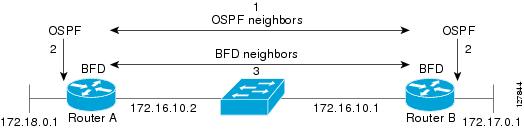
BFD provides fast BFD peer failure detection times independently of all media types, encapsulations, topologies, and routing protocols BGP, EIGRP, IS-IS, and OSPF. By sending rapid failure detection notices to the routing protocols in the local router to initiate the routing table recalculation process, BFD contributes to greatly reduced overall network convergence time. The figure below shows a simple network with two routers running OSPF and BFD. When OSPF discovers a neighbor (1) it sends a request to the local BFD process to initiate a BFD neighbor session with the OSPF neighbor router (2). The BFD neighbor session with the OSPF neighbor router is established (3).
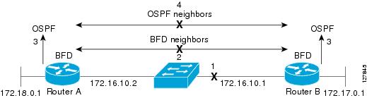
The figure below shows what happens when a failure occurs in the network (1). The BFD neighbor session with the OSPF neighbor router is torn down (2). BFD notifies the local OSPF process that the BFD neighbor is no longer reachable (3). The local OSPF process tears down the OSPF neighbor relationship (4). If an alternative path is available, the routers will immediately start converging on it.
A routing protocol needs to register with BFD for every neighbor it acquires. Once a neighbor is registered, BFD initiates a session with the neighbor if a session does not already exist.
OSPF registers with BFD when:
On broadcast interfaces, OSPF establishes a BFD session only with the designated router (DR) and backup designated router (BDR), but not between any two routers in DROTHER state.
BFD Detection of Failures
Once a BFD session has been established and timer negations are complete, BFD peers send BFD control packets that act in the same manner as an IGP hello protocol to detect liveliness, except at a more accelerated rate. The following information should be noted:
- BFD is a forwarding path failure detection protocol. BFD detects a failure, but the routing protocol must take action to bypass a failed peer.
- Typically, BFD can be used at any protocol layer. However, the Cisco implementation of BFD for Cisco IOS Releases 12.0(31)S, and 12.4(4)T supports only Layer 3 clients, in particular, the BGP, EIGRP, IS-IS, and OSPF routing protocols. For Cisco IOS Release 12.2(33)SRC, BFD is supported for static routing.
- The Cisco implementation of BFD for Cisco IOS Release 12.2(18)SXE also supports only Layer 3 clients and the EIGRP, IS-IS, and OSPF routing protocols. It does not support the BGP routing protocol.
- Cisco devices will use one BFD session for multiple client protocols in the Cisco implementation of BFD for Cisco IOS Releases 12.2(18)SXE, 12.0(31)S, and 12.4(4)T. For example, if a network is running OSPF and EIGRP across the same link to the same peer, only one BFD session will be established, and BFD will share session information with both routing protocols.
BFD Version Interoperability
Cisco IOS Release 12.4(9)T supports BFD Version 1 as well as BFD Version 0. All BFD sessions come up as Version 1 by default and will be interoperable with Version 0. The system automatically performs BFD version detection, and BFD sessions between neighbors will run in the highest common BFD version between neighbors. For example, if one BFD neighbor is running BFD Version 0 and the other BFD neighbor is running Version 1, the session will run BFD Version 0. The output from the show bfd neighbors [details] command will verify which BFD version a BFD neighbor is running.
See the Example Configuring BFD in an EIGRP Network with Echo Mode Enabled by Default for an example of BFD version detection.
BFD Support on Cisco 12000 Routers
The Cisco 12000 series routers support distributed BFD to take advantage of its distributed Route Processor (RP) and line card (LC) architecture. The BFD tasks will be divided and assigned to the BFD process on the RP and LC, as described in the following sections:
BFD Process on the RP
Client Interaction
The BFD process on the RP will handle the interaction with clients, which create and delete BFD sessions.
Session Management for the BFD Process on the RP
The BFD RP process will primarily own all BFD sessions on the router. It will pass the session creation and deletion requests to the BFD processes on all LCs. BFD LC sessions will have no knowledge of sessions being added or deleted by the clients. Only the BFD RP process will send session addition and deletion commands to the BFD LC process.
BFD Process on the LC
Session Management for the BFD Process on the LC
The BFD LC process manages sessions, adds and deletes commands from the BFD RP process, and creates and deletes new sessions based on the commands. In the event of transmit failure, receive failure, or session-down detection, the LC BFD instance will immediately notify the BFD RP process. It will also update transmit and receive counters. The BFD session is maintained completely on the LC. BFD control packets are received and processed, as well as sent, from the LC itself.
BFD Session Limits
In Cisco IOS Release 12.2(33)SRC, the number of BFD sessions that can be created has been increased to 128.
BFD Support for Nonbroadcast Media Interfaces
In Cisco IOS Release 12.2(33)SRC, the BFD feature is supported on nonbroadcast media interfaces including ATM, POS, serial, and VLAN interfaces. BFD support also extends to ATM, Frame Relay (FR), POS, and serial subinterfaces.
The bfd interval command must be configured on the interface to initiate BFD monitoring.
BFD Support for VPN Routing and Forwarding Interfaces
The BFD feature is extended in Cisco IOS Release 12.2(33)SRC to be VPN Routing and Forwarding (VRF) aware to provide fast detection of routing protocol failures between provider edge (PE) and customer edge (CE) routers.
BFD Support for Nonstop Forwarding with Stateful Switchover
Typically, when a networking device restarts, all routing peers of that device detect that the device went down and then came back up. This transition results in a routing flap, which could spread across multiple routing domains. Routing flaps caused by routing restarts create routing instabilities, which are detrimental to the overall network performance. Nonstop forwarding (NSF) helps to suppress routing flaps in devices that are enabled with stateful switchover (SSO), thereby reducing network instability.
NSF allows for the forwarding of data packets to continue along known routes while the routing protocol information is being restored after a switchover. With NSF, peer networking devices do not experience routing flaps. Data traffic is forwarded through intelligent line cards or dual forwarding processors while the standby RP assumes control from the failed active RP during a switchover. The ability of line cards and forwarding processors to remain up through a switchover and to be kept current with the Forwarding Information Base (FIB) on the active RP is key to NSF operation.
In devices that support dual RPs, SSO establishes one of the RPs as the active processor; the other RP is designated as the standby processor, and then synchronizes information between them. A switchover from the active to the standby processor occurs when the active RP fails, when it is removed from the networking device, or when it is manually taken down for maintenance.
In Cisco IOS Release 12.2(33)SRC, BFD sessions are placed in an âAdmin Downâ state during a planned switchover. The BFD configuration is synched from the active to standby processor, and all BFD clients re-register with the BFD process on the standby processor.
In Cisco IOS Release 12.2(33)SB, BFD is not SSO-aware, and it is not supported with NSF/SSO. These features should not be used together. Enabling BFD along with NSF/SSO causes the nonstop forwarding capability to break during failover because BFD adjacencies are not maintained and the routing clients are forced to mark down adjacencies and reconverge.
BFD Support for Stateful Switchover
The BFD protocol provides short-duration detection of failures in the path between adjacent forwarding engines. In network deployments that use dual RP routers or switches (to provide redundancy), the routers have a graceful restart mechanism that protects the forwarding state during a switchover between the active RP and the standby RP.
The dual RPs have variable switchover times that depend on the ability of the hardware to detect a communication failure. When BFD is running on the RP, some platforms are not able to detect a switchover before the BFD protocol times out; these platforms are referred to as slow switchover platforms.
Stateful BFD on the Standby RP
To ensure a successful switchover to the standby RP, the BFD protocol uses checkpoint messages to send session information from the active RP Cisco IOS instance to the standby RP Cisco IOS instance. The session information includes local and remote discriminators, adjacent router timer information, BFD setup information, and session-specific information such as the type of session and the session version. In addition, the BFD protocol sends session creation and deletion checkpoint messages to create or delete a session on the standby RP.
The BFD sessions on the standby RP do not receive or send packets and do not process expired timers. These sessions wait for a switchover to occur and then send packets for any active sessions so that sessions do not time out on adjacent routers.
When the BFD protocol on the standby RP is notified of a switchover it changes its state to active, registers itself with Cisco Express Forwarding so that it can receive packets, and then sends packets for any elements that have expired.
BFD also uses checkpoint messages to ensure that sessions created by clients on the active RP are maintained during a switchover. When a switchover occurs, BFD starts an SSO reclaim timer. Clients must reclaim their sessions within the duration specified by the reclaim timer or else the session is deleted.
Timer values are different based on the number of BFD sessions and the platform.
The table below describes the timer values on Cisco 7600 series routers.
| Table 1 | BFD Timer Values on a Cisco 7600 Series Router |
Note | The BFD SSO feature is supported on Cisco 7600 series routers in Cisco IOS Release 12.2(33)SRE and later releases. |
The table below describes the timer values on Cisco ASR 1000 Series Aggregation Services Routers.
| Table 2 | BFD Timer Values on a Cisco ASR 1000 Series Aggregation Services Router |
|
Maximum Number of BFD Sessions |
Chassis Type |
BFD Session Type |
Minimum Timer Value (ms) |
Clients |
Comments |
|---|---|---|---|---|---|
|
128 |
All |
Async/echo |
50 multiplier 3 |
All |
-- |
|
512 |
All |
Async/echo |
999 multiplier 3 |
All |
-- |
Note | The BFD SSO feature is supported on Cisco ASR 1000 Series Aggregation Services Routers in Cisco IOS Release 12.2(33)XNA and later releases. |
The table below describes the timer values on Cisco 6500 series routers.
| Table 3 | BFD Timer Values on a Cisco 6500 Series Router |
|
Maximum Number of BFD Sessions |
Chassis Type |
BFD Session Type |
Minimum Timer Value (ms) |
Clients |
Comments |
|---|---|---|---|---|---|
|
50 |
E-chassis/ 67xx line cards |
Async/Echo |
500 multiplier 3 |
All (except EIGRP) |
CFC line cards are not supported |
|
30 |
E-chassis/ 67xx line cards |
Async/Echo |
500 multiplier 3 |
EIGRP |
CFC line cards are not supported |
Note | The BFD SSO feature is supported on Cisco 6500 series routers in Cisco IOS Release 12.2(33)SXI 2 and later releases. |
The table below describes the timer values on a Cisco 10000 series routers.
| Table 4 | BFD Timer Values on a Cisco 10000 Series Router |
|
Maximum Number of BFD Sessions |
Chassis Type |
BFD Session Type |
Minimum Timer Value (ms) |
Clients |
Comments |
|---|---|---|---|---|---|
|
1100 |
PRE3/PRE4 |
Async/echo |
999 multiplier 5 |
All |
-- |
Note | The BFD SSO feature is supported on Cisco 10000 series routers in Cisco IOS Release 12.2(33)XNE later releases. |
BFD Support for Static Routing
Unlike dynamic routing protocols, such as OSPF and BGP, static routing has no method of peer discovery. Therefore, when BFD is configured, the reachability of the gateway is completely dependent on the state of the BFD session to the specified neighbor. Unless the BFD session is up, the gateway for the static route is considered unreachable, and therefore the affected routes will not be installed in the appropriate Routing Information Base (RIB).
For a BFD session to be successfully established, BFD must be configured on the interface on the peer and there must be a BFD client registered on the peer for the address of the BFD neighbor. When an interface is used by dynamic routing protocols, the latter requirement is usually met by configuring the routing protocol instances on each neighbor for BFD. When an interface is used exclusively for static routing, this requirement must be met by configuring static routes on the peers.
If a BFD configuration is removed from the remote peer while the BFD session is in the up state, the updated state of the BFD session is not signaled to IPv4 static. This will cause the static route to remain in the RIB. The only workaround is to remove the IPv4 static BFD neighbor configuration so that the static route no longer tracks BFD session state. Also, if you change the encapsulation type on a serial interface to one that is unsupported by BFD, BFD will be in a down state on that interface. The workaround is to shut down the interface, change to a supported encapsulation type, and then reconfigure BFD.
A single BFD session can be used by an IPv4 static client to track the reachability of next hops through a specific interface. You can assign a BFD group for a set of BFD-tracked static routes. Each group must have one active static BFD configuration, one or more passive BFD configurations, and the corresponding static routes to be BFD-tracked. Nongroup entries are BFD-tracked static routes for which a BFD group is not assigned. A BFD group must accommodate static BFD configurations that can be part of different VRFs. Effectively, the passive static BFD configurations need not be in the same VRF as that of the active configuration.
For each BFD group, there can be only one active static BFD session. You can configure the active BFD session by adding a static BFD configuration and a corresponding static route that uses the BFD configuration. The BFD session in a group is created only when there is an active static BFD configuration and the static route that uses the static BFD configuration. When the active static BFD configuration or the active static route is removed from a BFD group, all the passive static routes are withdrawn from the RIB. Effectively, all the passive static routes are inactive until an active static BFD configuration and a static route to be tracked by the active BFD session are configured in the group.
Similarly, for each BFD group, there can be one or more passive static BFD configurations and their corresponding static routes to be BFD-tracked. Passive static session routes take effect only when the active BFD session state is reachable. Though the active BFD session state of the group is reachable, the passive static route is added to the RIB only if the corresponding interface state is up. When a passive BFD session is removed from a group, it will not affect the active BFD session if one existed, or the BFD group reachability status.
BFD Control Channel over VCCV Support for ATM Pseudowire
Multiprotocol Label Switching (MPLS) pseudowires enable L2 traffic to be carried over an IP/MPLS core network. The BFD control channel over VCCV--Support for ATM Pseudowires feature provides operations and management (OAM) functions for MPLS pseudowires.
Note | This feature provides support for VCCV type 1 only. VCCV Type 1 is in-band VCCV and can be used only for MPLS pseudowires that use a control word. |
The BFD detection protocol can be used to provide OAM functionality to the MPLS protocol. VCCV provides a control channel associated with the pseudowire to provide OAM functions over that pseudowire. BFD can use the VCCV control channel as a pseudowire fault mechanism to detect dataplane failures. BFD can also use the VCCV control channel to carry the fault status of an attachment circuit (AC).
MPLS pseudowires can dynamically signal or statically configure virtual circuit (VC) labels. In dynamically signaled pseudowires, the control channel (CC) types and connection verification (CV) types are also signaled. In statically configured pseudowires, the CC and CV types must be configured on both ends of the pseudowire.
The CC types define whether VCCV packets are in-band or out-of-band for the pseudowire. The CV types define whether BFD monitoring is required for the pseudowire. If BFD monitoring is required for the pseudowire, the CV types also define how the BFD packets are encapsulated and whether BFD provides status signaling functionality.
Any protocol that requires BFD monitoring must register with BFD as a client. For example, the Xconnect protocol registers as a BFD client, and BFD assigns a client ID to Xconnect. Xconnect uses this client ID to create the BFD sessions that monitor the pseudowire.
BFD can detect forwarding failures (end-to-end) in the pseudowire path. When BFD detects a failure in the pseudowire forwarding path it notifies the Xconnect client that created the session. In addition, BFD can signal the status in any concatenated path, or AC, to the remote device where the BFD session is terminated.
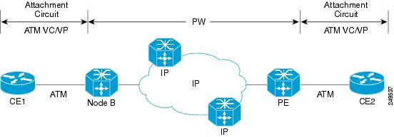
The figure below shows a dynamically signaled MPLS pseudowire carrying an ATM payload. In this example, BFD monitoring of the pseudowire occurs from the Node B device to the PE device. BFD also monitors the signal status of the ACs between the PE and CE2 device, and between the Node B and CE1 device.
BFD on Multiple Hops
Cisco IOS Release 15.1(3)S and later releases support BFD on arbitrary paths, which might span multiple network hops. The BFD Multihop feature provides subsecond forwarding failure detection for a destination more than one hop, and up to 255 hops, away.
A BFD multihop session is set up between a unique source-destination address pair provided by the client. A session can be set up between two endpoints that have IP connectivity.
You must configure the bfd-template andbfd map commands to create a multihop template and associate it with one or more maps of destinations and associated BFD timers. You can enable authentication and configure a key chain for BFD multihop sessions.
Benefits of Using BFD for Failure Detection
When you deploy any feature, it is important to consider all the alternatives and be aware of any trade-offs being made.
The closest alternative to BFD in conventional EIGRP, IS-IS, and OSPF deployments is the use of modified failure detection mechanisms for EIGRP, IS-IS, and OSPF routing protocols.
If you set EIGRP hello and hold timers to their absolute minimums, the failure detection rate for EIGRP falls to within a one- to two-second range.
If you use fast hellos for either IS-IS or OSPF, these Interior Gateway Protocol (IGP) protocols reduce their failure detection mechanisms to a minimum of one second.
There are several advantages to implementing BFD over reduced timer mechanisms for routing protocols:
- Although reducing the EIGRP, IS-IS, and OSPF timers can result in minimum detection timer of one to two seconds, BFD can provide failure detection in less than one second.
- Because BFD is not tied to any particular routing protocol, it can be used as a generic and consistent failure detection mechanism for EIGRP, IS-IS, and OSPF.
- Because some parts of BFD can be distributed to the data plane, it can be less CPU-intensive than the reduced EIGRP, IS-IS, and OSPF timers, which exist wholly at the control plane.
How to Configure Bidirectional Forwarding Detection
- Configuring BFD Session Parameters on the Interface
- Configuring BFD Support for Dynamic Routing Protocols
- Configuring BFD Support for Static Routing
- Configuring BFD Echo Mode
- Creating and Configuring BFD Templates
- Configuring a BFD Map
- Configuring BFD Control Channel over VCCV Support for ATM Pseudowire
- Monitoring and Troubleshooting BFD
Configuring BFD Session Parameters on the Interface
The steps in this procedure show how to configure BFD on the interface by setting the baseline BFD session parameters on an interface. Repeat the steps in this procedure for each interface over which you want to run BFD sessions to BFD neighbors.
DETAILED STEPS
Configuring BFD Support for Dynamic Routing Protocols
You can enable BFD support for dynamic routing protocols at the router level to enable BFD support globally for all interfaces or you can configure BFD on a per-interface basis at the interface level.
For Cisco IOS Release 12.2(18)SXE, you may configure BFD support for one or more of the following routing protocols: EIGRP, IS-IS, and OSPF.
For Cisco IOS Releases 12.2(33)SRA, you may configure BFD support for one or more of the following routing protocols: EIGRP, IS-IS, and OSPF.
For Cisco IOS Releases 12.2(33)SRB, you may configure BFD support for one or more of the following routing protocols: BGP, EIGRP, IS-IS, and OSPF.
For Cisco IOS Release 12.2(33)SRC, you may configure BFD support for static routing.
For Cisco IOS Releases 12.0(31)S and 12.4(4)T, you may configure BFD support for one or more of the following routing protocols: BGP, IS-IS, and OSPF.
For Cisco IOS Release 12.0(32)S, for the Cisco 10720 platform, you may configure BFD for one or more of the following routing protocols: BGP, IS-IS, and OSPF.
For Cisco IOS Release 12.4(11)T, BFD support for HSRP was introduced.
This section describes the following procedures:
- Configuring BFD Support for BGP
- Configuring BFD Support for EIGRP
- Configuring BFD Support for IS-IS
- Configuring BFD Support for OSPF
- Configuring BFD Support for HSRP
Configuring BFD Support for BGP
This section describes the procedure for configuring BFD support for BGP so that BGP is a registered protocol with BFD and will receive forwarding path detection failure messages from BFD.
BGP must be running on all participating routers.
The baseline parameters for BFD sessions on the interfaces over which you want to run BFD sessions to BFD neighbors must be configured. See the Configuring BFD Session Parameters on the Interface section for more information.
DETAILED STEPS
Configuring BFD Support for EIGRP
This section describes the procedure for configuring BFD support for EIGRP so that EIGRP is a registered protocol with BFD and will receive forwarding path detection failure messages from BFD. There are two methods for enabling BFD support for EIGRP:
- You can enable BFD for all of the interfaces for which EIGRP is routing by using the bfd all-interfaces command in router configuration mode.
- You can enable BFD for a subset of the interfaces for which EIGRP is routing by using the bfd interface type number command in router configuration mode.
EIGRP must be running on all participating routers.
The baseline parameters for BFD sessions on the interfaces over which you want to run BFD sessions to BFD neighbors must be configured. See the Configuring BFD Session Parameters on the Interface section for more information.
Note | Output from the show bfd neighbors details command shows the configured intervals. The output does not show intervals that were changed because hardware-offloaded BFD sessions were configured with Tx and Rx intervals that are not multiples of 50 ms. |
Note | BFD for EIGRP is not supported on the Cisco 12000 series routers for Cisco IOS Releases 12.0(31)S, 12.0(32)S, 12.4(4)T, and 12.2(33)SRA. > |
- bfd all-interfaces
- bfd interface type number
DETAILED STEPS
| Command or Action | Purpose | |||||
|---|---|---|---|---|---|---|
Step 1 |
enable
Example: Router> enable |
Enables privileged EXEC mode.
| ||||
Step 2 |
configure
terminal
Example: Router# configure terminal |
Enters global configuration mode. | ||||
Step 3 |
router
eigrp
as-number
Example: Router(config)# router eigrp 123 |
Configures the EIGRP routing process and enters router configuration mode. | ||||
Step 4 |
Enables BFD globally on all interfaces associated with the EIGRP routing process. or Enables BFD on a per-interface basis for one or more interfaces associated with the EIGRP routing process. | |||||
Step 5 |
end
Example: Router(config-router) end |
Exits router configuration mode and returns the router to privileged EXEC mode. | ||||
Step 6 |
show
bfd
neighbors
[details]
Example: Router# show bfd neighbors details |
(Optional) Verifies that the BFD neighbor is active and displays the routing protocols that BFD has registered.
| ||||
Step 7 |
show
ip
eigrp
interfaces
[type
number] [as-number] [detail]
Example: Router# show ip eigrp interfaces detail |
(Optional) Displays the interfaces for which BFD support for EIGRP has been enabled. |
Configuring BFD Support for IS-IS
This section describes the procedures for configuring BFD support for IS-IS so that IS-IS is a registered protocol with BFD and will receive forwarding path detection failure messages from BFD. There are two methods for enabling BFD support for IS-IS:
- You can enable BFD for all of the interfaces on which IS-IS is supporting IPv4 routing by using the bfd all-interfaces command in router configuration mode. You can then disable BFD for one or more of those interfaces using the isis bfd disable command in interface configuration mode.
- You can enable BFD for a subset of the interfaces for which IS-IS is routing by using the isis bfd command in interface configuration mode.
To configure BFD support for IS-IS, perform the steps in one of the following sections:
- Prerequisites
- Configuring BFD Support for IS-IS for All Interfaces
- What to Do Next
- Configuring BFD Support for IS-IS for One or More Interfaces
- What to Do Next
Prerequisites
IS-IS must be running on all participating routers.
The baseline parameters for BFD sessions on the interfaces that you want to run BFD sessions to BFD neighbors over must be configured. See the Configuring BFD Session Parameters on the Interface section for more information.
Note | Output from the show bfd neighbors details command shows the configured intervals. The output does not show intervals that were changed because hardware-offloaded BFD sessions were configured with Tx and Rx intervals that are not multiples of 50 ms. |
Configuring BFD Support for IS-IS for All Interfaces
To configure BFD on all IS-IS interfaces that support IPv4 routing, perform the steps in this section.
DETAILED STEPS
| Command or Action | Purpose | |||||
|---|---|---|---|---|---|---|
Step 1 |
enable
Example: Router> enable |
Enables privileged EXEC mode.
| ||||
Step 2 |
configure
terminal
Example: Router# configure terminal |
Enters global configuration mode. | ||||
Step 3 |
router
isis
area-tag
Example: Router(config)# router isis tag1 |
Specifies an IS-IS process and enters router configuration mode. | ||||
Step 4 |
bfd
all-interfaces
Example: Router(config-router)# bfd all-interfaces |
Enables BFD globally on all interfaces associated with the IS-IS routing process. | ||||
Step 5 |
exit
Example: Router(config-router)# exit |
(Optional) Returns the router to global configuration mode. | ||||
Step 6 |
interface
type
number
Example: Router(config)# interface fastethernet 6/0 |
(Optional) Enters interface configuration mode. | ||||
Step 7 |
ip
router
isis
[tag]
Example: Router(config-if)# ip router isis tag1 |
(Optional) Enables support for IPv4 routing on the interface. | ||||
Step 8 |
isis
bfd
[disable]
Example: Router(config-if)# isis bfd |
(Optional) Enables or disables BFD on a per-interface basis for one or more interfaces associated with the IS-IS routing process.
| ||||
Step 9 |
end
Example: Router(config-if)# end |
Exits interface configuration mode and returns the router to privileged EXEC mode. | ||||
Step 10 |
show
bfd
neighbors
[details]
Example: Router# show bfd neighbors details |
(Optional) Displays information that can be used to verify if the BFD neighbor is active and displays the routing protocols that BFD has registered.
| ||||
Step 11 |
show
clns
interface
Example: Router# show clns interface |
(Optional) Displays information that can be used to verify if BFD for IS-IS has been enabled for a specific IS-IS interface that is associated. |
What to Do Next
See the Monitoring and Troubleshooting BFD section for more information on monitoring and troubleshooting BFD. If you want to configure only for a specific subset of interfaces, perform the tasks in the Configuring BFD Support for IS-IS for One or More Interfaces section.
Configuring BFD Support for IS-IS for One or More Interfaces
To configure BFD for only one or more IS-IS interfaces, perform the steps in this section.
Note | Output from the show bfd neighbors details command shows the configured intervals. The output does not show intervals that were changed because hardware-offloaded BFD sessions were configured with Tx and Rx intervals that are not multiples of 50 ms. |
DETAILED STEPS
| Command or Action | Purpose | |||||
|---|---|---|---|---|---|---|
Step 1 |
enable
Example: Router> enable |
Enables privileged EXEC mode.
| ||||
Step 2 |
configure
terminal
Example: Router# configure terminal |
Enters global configuration mode. | ||||
Step 3 |
interface
type
number
Example: Router(config)# interface fastethernet 6/0 |
Enters interface configuration mode. | ||||
Step 4 |
ip
router
isis
[tag]
Example: Router(config-if)# ip router isis tag1 |
Enables support for IPv4 routing on the interface. | ||||
Step 5 |
isis
bfd
[disable]
Example: Router(config-if)# isis bfd |
Enables or disables BFD on a per-interface basis for one or more interfaces associated with the IS-IS routing process.
| ||||
Step 6 |
end
Example: Router(config-if)# end |
Exits interface configuration mode and returns the router to privileged EXEC mode. | ||||
Step 7 |
show
bfd
neighbors
[details] Example: Router# show bfd neighbors details |
(Optional) Displays information that can help verify if the BFD neighbor is active and displays the routing protocols that BFD has registered.
| ||||
Step 8 |
show
clns
interface
Example: Router# show clns interface |
(Optional) Displays information that can help verify if BFD for IS-IS has been enabled for a specific IS-IS interface that is associated. |
Configuring BFD Support for OSPF
This section describes the procedures for configuring BFD support for OSPF so that OSPF is a registered protocol with BFD and will receive forwarding path detection failure messages from BFD. You can either configure BFD support for OSPF globally on all interfaces or configure it selectively on one or more interfaces.
There are two methods for enabling BFD support for OSPF:
- You can enable BFD for all of the interfaces for which OSPF is routing by using the bfd all-interfaces command in router configuration mode. You can disable BFD support on individual interfaces using the ip ospf bfd [disable] command in interface configuration mode.
- You can enable BFD for a subset of the interfaces for which OSPF is routing by using the ip ospf bfd command in interface configuration mode.
See the following sections for tasks for configuring BFD support for OSPF:
- Configuring BFD Support for OSPF for All Interfaces
- What to Do Next
- Configuring BFD Support for OSPF for One or More Interfaces
- What to Do Next
Configuring BFD Support for OSPF for All Interfaces
To configure BFD for all OSPF interfaces, perform the steps in this section.
If you do not want to configure BFD on all OSPF interfaces and would rather configure BFD support specifically for one or more interfaces, see the Configuring BFD Support for OSPF for One or More Interfaces section.
OSPF must be running on all participating routers.
The baseline parameters for BFD sessions on the interfaces over which you want to run BFD sessions to BFD neighbors must be configured. See the Configuring BFD Session Parameters on the Interface section for more information.
Note | Output from the show bfd neighbors details command shows the configured intervals. The output does not show intervals that were changed because hardware-offloaded BFD sessions were configured with Tx and Rx intervals that are not multiples of 50 ms. |
DETAILED STEPS
| Command or Action | Purpose | |||||
|---|---|---|---|---|---|---|
Step 1 |
enable
Example: Router> enable |
Enables privileged EXEC mode.
| ||||
Step 2 |
configure
terminal
Example: Router# configure terminal |
Enters global configuration mode. | ||||
Step 3 |
router
ospf
process-id
Example: Router(config)# router ospf 4 |
Specifies an OSPF process and enters router configuration mode. | ||||
Step 4 |
bfd
all-interfaces
Example: Router(config-router)# bfd all-interfaces |
Enables BFD globally on all interfaces associated with the OSPF routing process. | ||||
Step 5 |
exit
Example: Router(config-router)# exit |
(Optional) Returns the router to global configuration mode. Enter this command only if you want to perform Step 7 to disable BFD for one or more interfaces. | ||||
Step 6 |
interface
type
number
Example: Router(config)# interface fastethernet 6/0 |
(Optional) Enters interface configuration mode. Enter this command only if you want to perform Step 7 to disable BFD for one or more interfaces. | ||||
Step 7 |
ip
ospf
bfd
[disable]
Example: Router(config-if)# ip ospf bfd disable |
(Optional) Disables BFD on a per-interface basis for one or more interfaces associated with the OSPF routing process.
| ||||
Step 8 |
end
Example: Router(config-if)# end |
Exits interface configuration mode and returns the router to privileged EXEC mode. | ||||
Step 9 |
show
bfd
neighbors
[details]
Example: Router# show bfd neighbors detail |
(Optional) Displays information that can help verify if the BFD neighbor is active and displays the routing protocols that BFD has registered.
| ||||
Step 10 |
show
ip
ospf
Example: Router# show ip ospf |
(Optional) Displays information that can help verify if BFD for OSPF has been enabled. |
What to Do Next
See the Monitoring and Troubleshooting BFD section for more information on monitoring and troubleshooting BFD. If you want to configure BFD support for another routing protocol, see the following sections:
Configuring BFD Support for OSPF for One or More Interfaces
OSPF must be running on all participating routers.
The baseline parameters for BFD sessions on the interfaces over which you want to run BFD sessions to BFD neighbors must be configured. See the Configuring BFD Session Parameters on the Interface section for more information.
Note | Output from the show bfd neighbors details command shows the configured intervals. The output does not show intervals that were changed because hardware-offloaded BFD sessions were configured with Tx and Rx intervals that are not multiples of 50 ms. |
DETAILED STEPS
| Command or Action | Purpose | |||||
|---|---|---|---|---|---|---|
Step 1 |
enable
Example: Router> enable |
Enables privileged EXEC mode.
| ||||
Step 2 |
configure
terminal
Example: Router# configure terminal |
Enters global configuration mode. | ||||
Step 3 |
interface
type
number
Example: Router(config)# interface fastethernet 6/0 |
Enters interface configuration mode. | ||||
Step 4 |
ip
ospf
bfd
[disable]
Example: Router(config-if)# ip ospf bfd |
Enables or disables BFD on a per-interface basis for one or more interfaces associated with the OSPF routing process.
| ||||
Step 5 |
end
Example: Router(config-if)# end |
Exits interface configuration mode and returns the router to privileged EXEC mode. | ||||
Step 6 |
show
bfd
neighbors
[details]
Example: Router# show bfd neighbors details |
(Optional) Displays information that can help verify if the BFD neighbor is active and displays the routing protocols that BFD has registered.
| ||||
Step 7 |
show
ip
ospf
Example: Router# show ip ospf |
(Optional) Displays information that can help verify if BFD support for OSPF has been enabled. |
Configuring BFD Support for HSRP
Perform this task to enable BFD support for Hot Standby Router Protocol (HSRP.) Repeat the steps in this procedure for each interface over which you want to run BFD sessions to HSRP peers.
HSRP supports BFD by default. If HSRP support for BFD has been manually disabled, you can reenable it at the router level to enable BFD support globally for all interfaces or on a per-interface basis at the interface level.
- HSRP must be running on all participating routers.
- Cisco Express Forwarding must be enabled.
DETAILED STEPS
| Command or Action | Purpose | |
|---|---|---|
Step 1 |
enable
Example: Router> enable |
Enables privileged EXEC mode.
|
Step 2 |
configure
terminal
Example: Router# configure terminal |
Enters global configuration mode. |
Step 3 |
ip
cef
[distributed] Example: Router(config)# ip cef |
Enables Cisco Express Forwarding or distributed Cisco Express Forwarding. |
Step 4 |
interface
type
number
Example: Router(config)# interface FastEthernet 6/0 |
Enters interface configuration mode. |
Step 5 |
ip
address
ip-address
mask
Example: Router(config-if)# ip address 10.0.0.11 255.255.255.0 |
Configures an IP address for the interface. |
Step 6 |
standby
[group-number] ip [ip-address [secondary]] Example: Router(config-if)# standby 1 ip 10.0.0.11 |
Activates HSRP. |
Step 7 |
standby
bfd
Example: Router(config-if)# standby bfd |
(Optional) Enables HSRP support for BFD on the interface. |
Step 8 |
exit
Example: Router(config-if)# exit |
Exits interface configuration mode. |
Step 9 |
standby
bfd
all-interfaces
Example: Router(config)# standby bfd all-interfaces |
(Optional) Enables HSRP support for BFD on all interfaces. |
Step 10 |
exit
Example: Router(config)# exit |
Exits global configuration mode. |
Step 11 |
show
standby
neighbors
Example: Router# show standby neighbors |
(Optional) Displays information about HSRP support for BFD. |
Configuring BFD Support for Static Routing
Perform this task to configure BFD support for static routing. Repeat the steps in this procedure on each BFD neighbor. For more information, see the Example Configuring BFD Support for Static Routing.
DETAILED STEPS
| Command or Action | Purpose | |
|---|---|---|
Step 1 |
enable
Example: Router> enable |
Enables privileged EXEC mode.
|
Step 2 |
configure
terminal
Example: Router# configure terminal |
Enters global configuration mode. |
Step 3 |
interface
type
number
Example: Router(config)# interface serial 2/0 |
Configures an interface and enters interface configuration mode. |
Step 4 |
ip
address
ip-address
mask
Example: Router(config-if)# ip address 10.201.201.1 255.255.255.0 |
Configures an IP address for the interface. |
Step 5 |
bfd
interval
milliseconds
min_rx
milliseconds
multiplier
interval-multiplier
Example: Router(config-if)# bfd interval 500 min_rx 500 multiplier 5 |
Enables BFD on the interface. |
Step 6 |
exit
Example: Router(config-if)# exit |
Exits interface configuration mode and returns to global configuration mode. |
Step 7 |
ip
route
static
bfd
interface-type
interface-number
ip-address
[
group
group-name
[
passive
]]
Example: Router(config)# ip route static bfd serial 2/0 10.1.1.1 group group1 passive |
Specifies a static route BFD neighbor.
|
Step 8 |
ip
route
[
vrf
vrf-name
]
prefix
mask
{ip-address |
interface-type
interface-number [ip-address]} [dhcp] [distance] [name
next-hop-name] [permanent |
track
number] [tag
tag]
Example: Router(config)# ip route 10.0.0.0 255.0.0.0 Example: Serial 2/0 10.201.201.2 |
Specifies a static route BFD neighbor. |
Step 9 |
exit
Example: Router(config)# exit |
Exits global configuration mode and returns to privileged EXEC mode. |
Step 10 |
show
ip
static
route
Example: Router# show ip static route |
(Optional) Displays static route database information. |
Step 11 |
show
ip
static
route
bfd
Example: Router# show ip static route bfd |
(Optional) Displays information about the static BFD configuration from the configured BFD groups and nongroup entries. |
Step 12 |
exit
Example: Router# exit |
Exits privileged EXEC mode and returns to user EXEC mode. |
Configuring BFD Echo Mode
BFD echo mode is enabled by default, but you can disable it such that it can run independently in each direction.
BFD echo mode works with asynchronous BFD. Echo packets are sent by the forwarding engine and forwarded back along the same path in order to perform detection--the BFD session at the other end does not participate in the actual forwarding of the echo packets. The echo function and the forwarding engine are responsible for the detection process; therefore, the number of BFD control packets that are sent out between two BFD neighbors is reduced. In addition, because the forwarding engine is testing the forwarding path on the remote (neighbor) system without involving the remote system, there is an opportunity to improve the interpacket delay variance, thereby achieving quicker failure detection times than when using BFD Version 0 with BFD control packets for the BFD session.
Echo mode is described as without asymmetry when it is running on both sides (both BFD neighbors are running echo mode).
Prerequisites
BFD must be running on all participating routers.
Before using BFD echo mode, you must disable the sending of Internet Control Message Protocol (ICMP) redirect messages by entering the no ip redirects command, in order to avoid high CPU utilization.
The baseline parameters for BFD sessions on the interfaces over which you want to run BFD sessions to BFD neighbors must be configured. See the Configuring BFD Session Parameters on the Interface section for more information.
Restrictions
BFD echo mode which is supported in BFD Version 1, is available only in Cisco IOS Releases 12.4(9)T, and 12.2(33)SRA.
This section contains the following configuration tasks for BFD echo mode:
Note | BFD echo mode does not work in conjunction with Unicast Reverse Path Forwarding (uRPF) configuration. If BFD echo mode and uRPF configurations are enabled, then the sessions will flap. |
Configuring the BFD Slow Timer
The steps in this procedure show how to change the value of the BFD slow timer. Repeat the steps in this procedure for each BFD router.
DETAILED STEPS
| Command or Action | Purpose | |
|---|---|---|
Step 1 |
enable
Example: Router> enable |
Enables privileged EXEC mode.
|
Step 2 |
configure
terminal
Example: Router# configure terminal |
Enters global configuration mode. |
Step 3 |
bfd
slow-timer
milliseconds
Example: Router(config)# bfd slow-timer 12000 |
Configures the BFD slow timer. |
Step 4 |
end
Example: Router(config)# end |
Exits global configuration mode and returns the router to privileged EXEC mode. |
Disabling BFD Echo Mode Without Asymmetry
The steps in this procedure show how to disable BFD echo mode without asymmetry --no echo packets will be sent by the router, and the router will not forward BFD echo packets that are received from any neighbor routers.
Repeat the steps in this procedure for each BFD router.
DETAILED STEPS
| Command or Action | Purpose | |
|---|---|---|
Step 1 |
enable
Example: Router> enable |
Enables privileged EXEC mode.
|
Step 2 |
configure
terminal
Example: Router# configure terminal |
Enters global configuration mode. |
Step 3 |
bfd
echo
Example: Router(config)# no bfd echo |
Enables BFD echo mode.
|
Step 4 |
end
Example: Router(config)# end |
Exits global configuration mode and returns the router to privileged EXEC mode. |
Creating and Configuring BFD Templates
You can configure a single-hop template to specify a set of BFD interval values. BFD interval values specified as part of the BFD template are not specific to a single interface. You can configure a multihop template to associate these values with one or more maps of destinations and associated BFD timers. You can enable authentication and configure a key chain for BFD multihop sessions.
Configuring a Single-Hop Template
Perform this task to create a BFD single-hop template and configure BFD interval timers.
Note | Cisco IOS Release 15.0(1)S introduced the concept of BFD templates that allow BFD interval timers to be configured independently of an interface. BFD templates are required to provide support for the BFD Control Channel over VCCV-Support for ATM Pseudowires feature. |
DETAILED STEPS
| Command or Action | Purpose | |
|---|---|---|
Step 1 |
enable
Example: Router> enable |
Enables privileged EXEC mode.
|
Step 2 |
configure
terminal
Example: Router# configure terminal |
Enters global configuration mode. |
Step 3 |
bfd-template
single-hop
template-name
Example: Router(config)# bfd-template single-hop bfdtemplate1 |
Creates a single-hop BFD template and enters BFD configuration mode. |
Step 4 |
interval
min-tx
milliseconds
min-rx
milliseconds
multiplier
multiplier-value
Example: Router(bfd-config)# interval min-tx 120 min-rx 100 multiplier 3 |
Configures the transmit and receive intervals between BFD packets, and specifies the number of consecutive BFD control packets that must be missed before BFD declares that a peer is unavailable. |
Step 5 |
end
Example: Router(bfd-config)# end |
Exits BFD configuration mode and returns the router to privileged EXEC mode. |
Configuring a Multihop Template
Perform this task to create a BFD multohop template and configure BFD interval timers, authentication, and key chain.
Note | Cisco IOS Release 15.1(3)S and later releases support BFD on multiple network hops. After you have configured interval timers and authentication in a template, you can configure a map to associate the template with unique source-destination address pairs for multihop BFD sessions. |
Note | See âXconnect as a Client of BFDâ for information on configuring xconnect as a client of BFD and detecting failure with the monitor peer bfd command. |
DETAILED STEPS
| Command or Action | Purpose | |
|---|---|---|
Step 1 |
enable
Example: Router> enable |
Enables privileged EXEC mode.
|
Step 2 |
configure
terminal
Example: Router# configure terminal |
Enters global configuration mode. |
Step 3 |
bfd-template
multi-hop
template-name
Example: Router(config)# bfd-template multi-hop mh-template1 |
Creates a BFD multihop BFD template and enters BFD configuration mode. |
Step 4 |
interval
min-tx
milliseconds
min-rx
milliseconds
multiplier
multiplier-value
Example: Router(bfd-config)# interval min-tx 120 min-rx 100 multiplier 3 |
Configures the transmit and receive intervals between BFD packets, and specifies the number of consecutive BFD control packets that must be missed before BFD declares that a peer is unavailable. |
Step 5 |
authentication
authentication-type
keychain
keychain-name
Example: Router(bfd-config)# authentication keyed-sha-1 keychain bfd-multihop |
Configures authentication for the multihop template and specifies the authentication type. |
Step 6 |
end
Example: Router(bfd-config)# end |
Exits BFD configuration mode and returns the router to privileged EXEC mode. |
Configuring a BFD Map
Perform this task to configure a BFD map that associates the interval timers and authentication configured in a template with unique source-destination address pairs for multihop BFD sessions.
DETAILED STEPS
| Command or Action | Purpose | |
|---|---|---|
Step 1 |
enable
Example: Router> enable |
Enables privileged EXEC mode.
|
Step 2 |
configure
terminal
Example: Router# configure terminal |
Enters global configuration mode. |
Step 3 |
bfd
mapipv4
vrf
vrf-name
destinationlengthsource-addresslengthtemplate-name
Example: Router(config)# bfd map ipv4 vrf vpn1 192.11.11.0/24 192.36.42.5/32 mh-template1 |
Configures a BFD map and associates it with the template. |
Step 4 |
end
Example: Router(config)# end |
Exits BFD configuration mode and returns the router to privileged EXEC mode. |
Configuring BFD Control Channel over VCCV Support for ATM Pseudowire
You must create and configure the BFD template before you assign it to the pseudowire class. For more information, see the Creating and Configuring BFD Templates section.
Before VCCV BFD can be run on pseudowires, pseudowires must be configured on the network.
DETAILED STEPS
| Command or Action | Purpose | |
|---|---|---|
Step 1 |
enable
Example: Router> enable |
Enables privileged EXEC mode.
|
Step 2 |
configure
terminal
Example: Router# configure terminal |
Enters global configuration mode. |
Step 3 |
pseudowire-class
name
Example: Router(config)# pseudowire-class vccv-bfd1 |
Specifies the name of the pseudowire class and enters pseudowire class configuration mode. |
Step 4 |
encapsulation
type
Example: Router(config-pw-class)# encapsulation mpls |
Specifies that MPLS is used as the data encapsulation method for tunneling Layer 2 traffic over the pseudowire.
|
Step 5 |
protoco
l {ldp |
none}
Example: Router(config-pw-class)# protocol none |
Specifies that no signaling is configured and that manually configured sessions are used.
|
Step 6 |
vccv
{control-word |
router-alert |
ttl}
Example: Router(config-pw-class)# vccv control-word |
Sets the MPLS pseudowire CC type.
|
Step 7 |
vccv
bfd
template
name
{udp |
raw-bfd}
Example: Router(config-pw-class)# vccv bfd template bfdtemplate1 raw-bfd |
Enables VCCV BFD for the pseudowire class. |
Step 8 |
vccv
bfd
status
signaling
Example: Router(config-pw-class)# vccv bfd status signaling |
Enables status signaling for BFD VCCV. |
Step 9 |
exit
Example: Router(config-pw-class)# exit |
Exits pseudowire class configuration mode and returns to global configuration mode. |
Step 10 |
interface
atm
interface-number
Example: Router(config)# interface atm 9/0/0 |
Configures an ATM interface and enters interface configuration mode |
Step 11 |
atm
asynchronous
Example: Router(config-if)# atm asynchronous |
Enables asynchronous mode on the ATM interface. |
Step 12 |
pvc
vpi/
vci
l2transport
Example: Router(config-if)# pvc 0/100 l2transport |
Creates the ATM permanent virtual circuit (PVC), specifies the encapsulation type on an ATM PVC, and enters ATM virtual circuit configuration mode. |
Step 13 |
xconnect
peer-ip-address
vc-id
{encapsulation
mpls [manual] |
pw-class
pw-class-name} [pw-class
pw-class-name] [sequencing {transmit |
receive |
both}]
Example: Router(cfg-if-atm-l2trans-pvc)# xconnect 10.0.0.7 100 pw-class vccv-bfd1 |
Binds an attachment circuit to a pseudowire, configures an AToM static pseudowire, and specifies the pseudowire class. |
Step 14 |
end
Example: Router(cfg-if-atm-l2trans-pvc)# end |
Exits ATM virtual circuit configuration mode and returns to global configuration mode. |
Monitoring and Troubleshooting BFD
This section describes how to retrieve BFD information for maintenance and troubleshooting. The commands in these tasks can be entered as needed, in any order desired.
For more information about BFD session initiation and failure, refer to the BFD Operation.
This section contains information for monitoring and troubleshooting BFD for the following Cisco platforms:
- Monitoring and Troubleshooting BFD for Cisco 7600 Series Routers
- Monitoring and Troubleshooting BFD for Cisco 12000 Series Routers
- Monitoring and Troubleshooting BFD for Cisco 10720 Internet Routers
Monitoring and Troubleshooting BFD for Cisco 7600 Series Routers
To monitor or troubleshoot BFD on Cisco 7600 series routers, perform one or more of the steps in this section.
Note | See the âConfiguring Synchronous Ethernet on the Cisco 7600 Router with ES+ Line Card â section of the Cisco 7600 Series Ethernet Services Plus (ES+) and Ethernet Services Plus T (ES+T) Line Card Configuration Guide for more information about troubleshooting BFD on Cisco 7600 series routers. |
DETAILED STEPS
| Command or Action | Purpose | |||||
|---|---|---|---|---|---|---|
Step 1 |
enable
Example: Router> enable |
Enables privileged EXEC mode.
| ||||
Step 2 |
show
bfd
neighbors
[details]
Example: Router# show bfd neighbors details |
(Optional) Displays the BFD adjacency database.
| ||||
Step 3 |
debug
bfd
[packet |
event]
Example: Router# debug bfd packet |
(Optional) Displays debugging information about BFD packets. |
Monitoring and Troubleshooting BFD for Cisco 12000 Series Routers
To monitor or troubleshoot BFD on Cisco 12000 series routers, perform one or more of the steps in this section.
DETAILED STEPS
| Command or Action | Purpose | |||||
|---|---|---|---|---|---|---|
Step 1 |
enable
Example: Router> enable |
Enables privileged EXEC mode.
| ||||
Step 2 |
attach
slot-number
Example: Router# attach 6 |
Connects you to a specific line card for the purpose of executing monitoring and maintenance commands on the specified line card. Slot numbers range from 0 to 11 for the Cisco 12012 and from 0 to 7 for the Cisco 12008.
| ||||
Step 3 |
show
bfd
neighbors
[details] Example: Router# show bfd neighbors details |
Displays the BFD adjacency database.
| ||||
Step 4 |
show
monitor
event-trace
bfd
[all] Example: Router# show monitor event-trace bfd all |
Displays logged messages for important events in ârecent pastâ on BFD activities that occur on the line cards. This is a rolling buffer based log, so âdistant pastâ events would be lost. Depending on traffic and frequency of events, these events could be seen over a variable time window. | ||||
Step 5 |
debug
bfd
event
Example: Router# debug bfd event |
Displays debugging information about BFD state transitions. | ||||
Step 6 |
debug
bfd
packet
Example: Router# debug bfd packet |
Displays debugging information about BFD control packets. | ||||
Step 7 |
debug
bfd
ipc-error
Example: Router# debug bfd ipc-error |
Displays debugging information with IPC errors on the RP and LC. | ||||
Step 8 |
debug
bfd
ipc-event
Example: Router# debug bfd ipc-event |
Displays debugging information with IPC events on the RP and LC. | ||||
Step 9 |
debug
bfd
oir-error
Example: Router# debug bfd oir-error |
Displays debugging information with OIR errors on the RP and LC. | ||||
Step 10 |
debug
bfd
oir-event
Example: Router# debug bfd oir-event |
Displays debugging information with OIR events on the RP and LC. |
Monitoring and Troubleshooting BFD for Cisco 10720 Internet Routers
To monitor or troubleshoot BFD on Cisco 10720 Internet routers, perform one or more of the steps in this section.
DETAILED STEPS
| Command or Action | Purpose | |||
|---|---|---|---|---|
Step 1 |
enable
Example: Router> enable |
Enables privileged EXEC mode.
| ||
Step 2 |
show
bfd
neighbors
[details] Example: Router# show bfd neighbors details |
(Optional) Displays the BFD adjacency database.
| ||
Step 3 |
debug
bfd
event
Example: Router# debug bfd event |
(Optional) Displays debugging information about BFD state transitions. | ||
Step 4 |
debug
bfd
packet
Example: Router# debug bfd packet |
(Optional) Displays debugging information about BFD control packets. |
Configuration Examples for Bidirectional Forwarding Detection
- Example Configuring BFD in an EIGRP Network with Echo Mode Enabled by Default
- Example Configuring BFD in an OSPF Network
- Example Configuring BFD in a BGP Network
- Example Configuring BFD in an IS-IS Network
- Example Configuring BFD in an HSRP Network
- Example Configuring BFD Support for Static Routing
- Example Configuring BFD Control Channel over VCCV--Support for ATM Pseudowire
Example Configuring BFD in an EIGRP Network with Echo Mode Enabled by Default
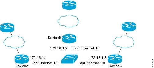
The following example shows how to configure BFD in an EIGRP network with echo mode enabled by default in Cisco IOS Release 12.4(9)T. In the following example, the EIGRP network contains RouterA, RouterB, and RouterC. Fast Ethernet interface 1/0 on RouterA is connected to the same network as Fast Ethernet interface 1/0 on Router B. Fast Ethernet interface 1/0 on RouterB is connected to the same network as Fast Ethernet interface 1/0 on RouterC.
RouterA and RouterB are running BFD Version 1, which supports echo mode, and RouterC is running BFD Version 0, which does not support echo mode. The BFD sessions between RouterC and its BFD neighbors are said to be running echo mode with asymmetry because echo mode will run on the forwarding path for RouteA and RouterB, and their echo packets will return along the same path for BFD sessions and failure detections, while their BFD neighbor RouterC runs BFD Version 0 and uses BFD controls packets for BFD sessions and failure detections.
The figure below shows a large EIGRP network with several routers, three of which are BFD neighbors that are running EIGRP as their routing protocol.
The example, starting in global configuration mode, shows the configuration of BFD.
Configuration for RouterA
interface Fast Ethernet0/0
 no shutdown
 ip address 10.4.9.14 255.255.255.0
 duplex auto
 speed auto
!
interface Fast Ethernet1/0
 ip address 172.16.1.1 255.255.255.0
 bfd interval 50 min_rx 50 multiplier 3
 no shutdown
 duplex auto
 speed auto
!
router eigrp 11
 network 172.16.0.0
 bfd all-interfaces
 auto-summary
!
ip default-gateway 10.4.9.1
ip default-network 0.0.0.0
ip route 0.0.0.0 0.0.0.0 10.4.9.1
ip route 172.16.1.129 255.255.255.255 10.4.9.1
!
no ip http server
!
logging alarm informational
!
control-plane
!
line con 0
 exec-timeout 30 0
 stopbits 1
line aux 0
 stopbits 1
line vty 0 4
 login
!
!
end
Configuration for RouterB
!
interface Fast Ethernet0/0
 no shutdown
 ip address 10.4.9.34 255.255.255.0
 duplex auto
 speed auto
!
interface Fast Ethernet1/0
 ip address 172.16.1.2 255.255.255.0
 bfd interval 50 min_rx 50 multiplier 3
 no shtdown
 duplex auto
 speed auto
!
router eigrp 11
 network 172.16.0.0
 bfd all-interfaces
 auto-summary
!
ip default-gateway 10.4.9.1
ip default-network 0.0.0.0
ip route 0.0.0.0 0.0.0.0 10.4.9.1
ip route 172.16.1.129 255.255.255.255 10.4.9.1
!
no ip http server
!
logging alarm informational
!
control-plane
!
line con 0
 exec-timeout 30 0
 stopbits 1
line aux 0
 stopbits 1
line vty 0 4
 login
!
!
end
Configuration for RouterC
!
!
interface Fast Ethernet0/0
 no shutdown
 ip address 10.4.9.34 255.255.255.0
 duplex auto
 speed auto
!
interface Fast Ethernet1/0
 ip address 172.16.1.2 255.255.255.0
 bfd interval 50 min_rx 50 multiplier 3
 no shutdown
 duplex auto
 speed auto
!
router eigrp 11
 network 172.16.0.0
 bfd all-interfaces
 auto-summary
!
ip default-gateway 10.4.9.1
ip default-network 0.0.0.0
ip route 0.0.0.0 0.0.0.0 10.4.9.1
ip route 172.16.1.129 255.255.255.255 10.4.9.1
!
no ip http server
!
logging alarm informational
!
control-plane
!
line con 0
 exec-timeout 30 0
 stopbits 1
line aux 0
 stopbits 1
line vty 0 4
 login
!
!
end
The output from the show bfd neighbors detailscommand from RouterA verifies that BFD sessions have been created among all three routers and that EIGRP is registered for BFD support. The first group of output shows that RouterC with the IP address 172.16.1.3 runs BFD Version 0 and therefore does not use the echo mode. The second group of output shows that RouterB with the IP address 172.16.1.2 does run BFD Version 1, and the 50 millisecond BFD interval parameter had been adopted. The relevant command output is shown in bold in the output.
RouterA
RouterA# show bfd neighbors details
OurAddr
       NeighAddr
      LD/RD  RH/RS    Holdown(mult)  State     Int
172.16.1.1    172.16.1.3
     5/3    1(RH)    150 (3 )       Up   Fa1/0
Session state is UP and not using echo function.
Local Diag: 0, Demand mode: 0, Poll bit: 0
MinTxInt: 50000, MinRxInt: 50000, Multiplier: 3
Received MinRxInt: 50000, Received Multiplier: 3
Holdown (hits): 150(0), Hello (hits): 50(1364284)
Rx Count: 1351813, Rx Interval (ms) min/max/avg: 28/64/49 last: 4 ms ago
Tx Count: 1364289, Tx Interval (ms) min/max/avg: 40/68/49 last: 32 ms ago
Registered protocols: EIGRP
Uptime: 18:42:45
Last packet: Version: 0
            - Diagnostic: 0
             I Hear You bit: 1     - Demand bit: 0
             Poll bit: 0           - Final bit: 0
             Multiplier: 3         - Length: 24
             My Discr.: 3          - Your Discr.: 5
             Min tx interval: 50000    - Min rx interval: 50000
             Min Echo interval: 0
OurAddr       NeighAddr
     LD/RD  RH/RS   Holdown(mult)  State     Int
172.16.1.1    172.16.1.2

    6/1    Up        0    (3 )   Up        Fa1/0
Session state is UP and using echo function with 50 ms interval.
Local Diag: 0, Demand mode: 0, Poll bit: 0
MinTxInt: 1000000, MinRxInt: 1000000, Multiplier: 3
Received MinRxInt: 1000000, Received Multiplier: 3
Holdown (hits): 3000(0), Hello (hits): 1000(317)
Rx Count: 305, Rx Interval (ms) min/max/avg: 1/1016/887 last: 448 ms ago
Tx Count: 319, Tx Interval (ms) min/max/avg: 1/1008/880 last: 532 ms ago
Registered protocols: EIGRP
Uptime: 00:04:30
Last packet: Version: 1

         - Diagnostic: 0
             State bit: Up         - Demand bit: 0
             Poll bit: 0           - Final bit: 0
             Multiplier: 3         - Length: 24
             My Discr.: 1          - Your Discr.: 6
             Min tx interval: 1000000    - Min rx interval: 1000000
             Min Echo interval: 50000
The output from the show bfd neighbors detailscommand on Router B verifies that BFD sessions have been created and that EIGRP is registered for BFD support. As previously noted, RouterA runs BFD Version 1, therefore echo mode is running, and RouterC runs BFD Version 0, so echo mode does not run. The relevant command output is shown in bold in the output.
Router B
RouterB# show bfd neighbors details
OurAddr       NeighAddr
     LD/RD  RH/RS   Holdown(mult)  State     Int
172.16.1.2    172.16.1.1
    1/6    Up        0    (3 )   Up        Fa1/0
Session state is UP and using echo function with 50 ms interval.
Local Diag: 0, Demand mode: 0, Poll bit: 0
MinTxInt: 1000000, MinRxInt: 1000000, Multiplier: 3
Received MinRxInt: 1000000, Received Multiplier: 3
Holdown (hits): 3000(0), Hello (hits): 1000(337)
Rx Count: 341, Rx Interval (ms) min/max/avg: 1/1008/882 last: 364 ms ago
Tx Count: 339, Tx Interval (ms) min/max/avg: 1/1016/886 last: 632 ms ago
Registered protocols: EIGRP
Uptime: 00:05:00
Last packet: Version: 1
           - Diagnostic: 0
             State bit: Up         - Demand bit: 0
             Poll bit: 0           - Final bit: 0
             Multiplier: 3         - Length: 24
             My Discr.: 6          - Your Discr.: 1
             Min tx interval: 1000000    - Min rx interval: 1000000
             Min Echo interval: 50000
OurAddr       NeighAddr

 LD/RD  RH/RS   Holdown(mult)  State     Int
172.16.1.2    172.16.1.3
     3/6    1(RH)     118  (3 )   Up        Fa1/0
Session state is UP and not using echo function.
Local Diag: 0, Demand mode: 0, Poll bit: 0
MinTxInt: 50000, MinRxInt: 50000, Multiplier: 3
Received MinRxInt: 50000, Received Multiplier: 3
Holdown (hits): 150(0), Hello (hits): 50(5735)
Rx Count: 5731, Rx Interval (ms) min/max/avg: 32/72/49 last: 32 ms ago
Tx Count: 5740, Tx Interval (ms) min/max/avg: 40/64/50 last: 44 ms ago
Registered protocols: EIGRP
Uptime: 00:04:45
Last packet: Version: 0
            - Diagnostic: 0
             I Hear You bit: 1     - Demand bit: 0
             Poll bit: 0           - Final bit: 0
             Multiplier: 3         - Length: 24
             My Discr.: 6          - Your Discr.: 3
             Min tx interval: 50000    - Min rx interval: 50000
             Min Echo interval: 0
The figure below shows that Fast Ethernet interface 1/0 on RouterB has failed. When Fast Ethernet interface 1/0 on RouterB is shut down, the BFD statistics of the corresponding BFD sessions on RouterA and RouterB are reduced.
When Fast Ethernet interface 1/0 on RouterB fails, BFD will no longer detect Router B as a BFD neighbor for RouterA or for RouterC. In this example, Fast Ethernet interface 1/0 has been administratively shut down on RouterB.
The following output from the show bfd neighbors command on RouterA now shows only one BFD neighbor for RouterA in the EIGRP network. The relevant command output is shown in bold in the output.
RouterA# show bfd neighbors
OurAddr       NeighAddr

    LD/RD  RH/RS   Holdown(mult)  State     Int
172.16.1.1    172.16.1.3

    5/3    1(RH)     134  (3 )   Up        Fa1/0
The following output from the show bfd neighbors command on RouterC also now shows only one BFD neighbor for RouterC in the EIGRP network. The relevant command output is shown in bold in the output.
RouterC# show bfd neighbors
OurAddr       NeighAddr

   LD/RD RH  Holdown(mult)  State     Int
172.16.1.3    172.16.1.1

    3/5  1   114  (3 )      Up        Fa1/0
Example Configuring BFD in an OSPF Network
The following example shows how to configure BFD in an OSPF network in Cisco IOS Release 12.0(31)S. In the following example, the simple OSPF network consists of Router A and Router B. Fast Ethernet interface 0/1 on Router A is connected to the same network as Fast Ethernet interface 6/0 in Router B. The example, starting in global configuration mode, shows the configuration of BFD. For both Routers A and B, BFD is configured globally for all interfaces associated with the OSPF process.
Configuration for Router A
!
interface Fast Ethernet 0/1
 ip address 172.16.10.1 255.255.255.0
 bfd interval 50 min_rx 50 multiplier 3
!
interface Fast Ethernet 3/0.1
ip address 172.17.0.1 255.255.255.0
!
router ospf 123
 log-adjacency-changes detail
 network 172.16.0.0 0.0.0.255 area 0
 network 172.17.0.0 0.0.0.255 area 0
 bfd all-interfaces
Configuration for Router B
!
interface Fast Ethernet 6/0
 ip address 172.16.10.2 255.255.255.0
 bfd interval 50 min_rx 50 multiplier 3
!
interface Fast Ethernet 6/1
 ip address 172.18.0.1 255.255.255.0
!
router ospf 123
 log-adjacency-changes detail
 network 172.16.0.0 0.0.255.255 area 0
 network 172.18.0.0 0.0.255.255 area 0
 bfd all-interfaces
The output from the show bfd neighbors detailscommand verifies that a BFD session has been created and that OSPF is registered for BFD support. The relevant command output is shown in bold in the output.
Router A
RouterA# show bfd neighbors details
OurAddr       NeighAddr     LD/RD RH  Holdown(mult)  State     Int
172.16.10.1   172.16.10.2    1/2  1   532  (3 )      Up        Fa0/1
Local Diag: 0, Demand mode: 0, Poll bit: 0
MinTxInt: 200000, MinRxInt: 200000, Multiplier: 5
Received MinRxInt: 1000, Received Multiplier: 3
Holdown (hits): 600(22), Hello (hits): 200(84453)
Rx Count: 49824, Rx Interval (ms) min/max/avg: 208/440/332 last: 68 ms ago
Tx Count: 84488, Tx Interval (ms) min/max/avg: 152/248/196 last: 192 ms ago
Registered protocols: OSPF
Uptime: 02:18:49
Last packet: Version: 0
            - Diagnostic: 0
             I Hear You bit: 1     - Demand bit: 0
             Poll bit: 0           - Final bit: 0
             Multiplier: 3         - Length: 24
             My Discr.: 2          - Your Discr.: 1
             Min tx interval: 50000    - Min rx interval: 1000
             Min Echo interval: 0
The output from the show bfd neighbors detailscommand from the line card on Router B verifies that a BFD session has been created:
Note | Router B is a Cisco 12000 series router. The show bfd neighbors detailscommand must be run on the line cards. The show bfd neighbors detailscommand will not display the registered protocols when it is entered on a line card. |
Router B
RouterB# attach 6
Entering Console for 8 Port Fast Ethernet in Slot: 6
Type "exit" to end this session
Press RETURN to get started!
Router> show bfd neighbors details
Cleanup timer hits: 0
OurAddr       NeighAddr     LD/RD RH  Holdown(mult)  State     Int
172.16.10.2   172.16.10.1    8/1  1   1000 (5 )      Up        Fa6/0
Local Diag: 0, Demand mode: 0, Poll bit: 0
MinTxInt: 50000, MinRxInt: 1000, Multiplier: 3
Received MinRxInt: 200000, Received Multiplier: 5
Holdown (hits): 1000(0), Hello (hits): 200(5995)
Rx Count: 10126, Rx Interval (ms) min/max/avg: 152/248/196 last: 0 ms ago
Tx Count: 5998, Tx Interval (ms) min/max/avg: 204/440/332 last: 12 ms ago
Last packet: Version: 0            - Diagnostic: 0
             I Hear You bit: 1     - Demand bit: 0
             Poll bit: 0           - Final bit: 0
             Multiplier: 5         - Length: 24
             My Discr.: 1          - Your Discr.: 8
             Min tx interval: 200000    - Min rx interval: 200000
             Min Echo interval: 0
Uptime: 00:33:13
SSO Cleanup Timer called: 0
SSO Cleanup Action Taken: 0
Pseudo pre-emptive process count: 239103 min/max/avg: 8/16/8 last: 0 ms ago
 IPC Tx Failure Count: 0
 IPC Rx Failure Count: 0
 Total Adjs Found: 1
The output of the show ip ospfcommand verifies that BFD has been enabled for OSPF. The relevant command output is shown in bold in the output.
Router A
RouterA# show ip ospf
 Routing Process "ospf 123" with ID 172.16.10.1
 Supports only single TOS(TOS0) routes
 Supports opaque LSA
 Supports Link-local Signaling (LLS)
 Initial SPF schedule delay 5000 msecs
 Minimum hold time between two consecutive SPFs 10000 msecs
 Maximum wait time between two consecutive SPFs 10000 msecs
 Incremental-SPF disabled
 Minimum LSA interval 5 secs
 Minimum LSA arrival 1000 msecs
 LSA group pacing timer 240 secs
 Interface flood pacing timer 33 msecs
 Retransmission pacing timer 66 msecs
 Number of external LSA 0. Checksum Sum 0x000000
 Number of opaque AS LSA 0. Checksum Sum 0x000000
 Number of DCbitless external and opaque AS LSA 0
 Number of DoNotAge external and opaque AS LSA 0
 Number of areas in this router is 1. 1 normal 0 stub 0 nssa
 External flood list length 0
BFD is enabled
    Area BACKBONE(0)
        Number of interfaces in this area is 2 (1 loopback)
        Area has no authentication
        SPF algorithm last executed 00:00:08.828 ago
        SPF algorithm executed 9 times
        Area ranges are
        Number of LSA 3. Checksum Sum 0x028417
        Number of opaque link LSA 0. Checksum Sum 0x000000
        Number of DCbitless LSA 0
        Number of indication LSA 0
        Number of DoNotAge LSA 0
        Flood list length 0
Router B
RouterB# show ip ospf
 Routing Process "ospf 123" with ID 172.18.0.1
 Supports only single TOS(TOS0) routes
 Supports opaque LSA
 Supports Link-local Signaling (LLS)
 Supports area transit capability
 Initial SPF schedule delay 5000 msecs
 Minimum hold time between two consecutive SPFs 10000 msecs
 Maximum wait time between two consecutive SPFs 10000 msecs
 Incremental-SPF disabled
 Minimum LSA interval 5 secs
 Minimum LSA arrival 1000 msecs
 LSA group pacing timer 240 secs
 Interface flood pacing timer 33 msecs
 Retransmission pacing timer 66 msecs
 Number of external LSA 0. Checksum Sum 0x0
 Number of opaque AS LSA 0. Checksum Sum 0x0
 Number of DCbitless external and opaque AS LSA 0
 Number of DoNotAge external and opaque AS LSA 0
 Number of areas in this router is 1. 1 normal 0 stub 0 nssa
 Number of areas transit capable is 0
 External flood list length 0
BFD is enabled
    Area BACKBONE(0)
        Number of interfaces in this area is 2 (1 loopback)
        Area has no authentication
        SPF algorithm last executed 02:07:30.932 ago
        SPF algorithm executed 7 times
        Area ranges are
        Number of LSA 3. Checksum Sum 0x28417
        Number of opaque link LSA 0. Checksum Sum 0x0
        Number of DCbitless LSA 0
        Number of indication LSA 0
        Number of DoNotAge LSA 0
        Flood list length 0
The output of the show ip ospf interfacecommand verifies that BFD has been enabled for OSPF on the interfaces connecting Router A and Router B. The relevant command output is shown in bold in the output.
Router A
RouterA# show ip ospf interface Fast Ethernet 0/1
show ip ospf interface Fast Ethernet 0/1
Fast Ethernet0/1 is up, line protocol is up
  Internet Address 172.16.10.1/24, Area 0
  Process ID 123, Router ID 172.16.10.1, Network Type BROADCAST, Cost: 1
  Transmit Delay is 1 sec, State BDR, Priority 1, BFD enabled
  Designated Router (ID) 172.18.0.1, Interface address 172.16.10.2
  Backup Designated router (ID) 172.16.10.1, Interface address 172.16.10.1
  Timer intervals configured, Hello 10, Dead 40, Wait 40, Retransmit 5
    oob-resync timeout 40
    Hello due in 00:00:03
  Supports Link-local Signaling (LLS)
  Index 1/1, flood queue length 0
  Next 0x0(0)/0x0(0)
  Last flood scan length is 1, maximum is 1
  Last flood scan time is 0 msec, maximum is 0 msec
  Neighbor Count is 1, Adjacent neighbor count is 1
    Adjacent with neighbor 172.18.0.1  (Designated Router)
  Suppress hello for 0 neighbor(s)
Router B
RouterB# show ip ospf interface Fast Ethernet 6/1
Fast Ethernet6/1 is up, line protocol is up
  Internet Address 172.18.0.1/24, Area 0
  Process ID 123, Router ID 172.18.0.1, Network Type BROADCAST, Cost: 1
  Transmit Delay is 1 sec, State DR, Priority 1, BFD enabled
  Designated Router (ID) 172.18.0.1, Interface address 172.18.0.1
  No backup designated router on this network
  Timer intervals configured, Hello 10, Dead 40, Wait 40, Retransmit 5
    oob-resync timeout 40
    Hello due in 00:00:01
  Supports Link-local Signaling (LLS)
  Index 1/1, flood queue length 0
  Next 0x0(0)/0x0(0)
  Last flood scan length is 0, maximum is 0
  Last flood scan time is 0 msec, maximum is 0 msec
  Neighbor Count is 0, Adjacent neighbor count is 0
  Suppress hello for 0 neighbor(s)
Example Configuring BFD in a BGP Network
The following example shows how to configure BFD in a BGP network in Cisco IOS Release 12.0(31)S. In the following example, the simple BGP network consists of Router A and Router B. Fast Ethernet interface 0/1 on Router A is connected to the same network as Fast Ethernet interface 6/0 in Router B. The example, starting in global configuration mode, shows the configuration of BFD.
Configuration for Router A
!
interface Fast Ethernet 0/1
 ip address 172.16.10.1 255.255.255.0
 bfd interval 50 min_rx 50 multiplier 3
!
interface Fast Ethernet 3/0.1
ip address 172.17.0.1 255.255.255.0
!
!
router bgp 40000
 bgp log-neighbor-changes
 neighbor 172.16.10.2 remote-as 45000
 neighbor 172.16.10.2 fall-over bfd
 !
 address-family ipv4
 neighbor 172.16.10.2 activate
 no auto-summary
 no synchronization
 network 172.18.0.0 mask 255.255.255.0
 exit-address-family
!
Configuration for Router B
!
interface Fast Ethernet 6/0
 ip address 172.16.10.2 255.255.255.0
 bfd interval 50 min_rx 50 multiplier 3
!
interface Fast Ethernet 6/1
 ip address 172.18.0.1 255.255.255.0
!
router bgp 45000
 bgp log-neighbor-changes
 neighbor 172.16.10.1 remote-as 40000
 neighbor 172.16.10.1 fall-over bfd
 !
 address-family ipv4
 neighbor 172.16.10.1 activate
 no auto-summary
 no synchronization
 network 172.17.0.0 mask 255.255.255.0
 exit-address-family
!
The output from the show bfd neighbors detailscommand from Router A verifies that a BFD session has been created and that BGP is registered for BFD support. The relevant command output is shown in bold in the output.
Router A
RouterA# show bfd neighbors details

OurAddr       NeighAddr     LD/RD RH  Holdown(mult)  State     Int
172.16.10.1   172.16.10.2    1/8  1   332  (3 )      Up        Fa0/1
Local Diag: 0, Demand mode: 0, Poll bit: 0
MinTxInt: 200000, MinRxInt: 200000, Multiplier: 5
Received MinRxInt: 1000, Received Multiplier: 3
Holdown (hits): 600(0), Hello (hits): 200(15491)
Rx Count: 9160, Rx Interval (ms) min/max/avg: 200/440/332 last: 268 ms ago
Tx Count: 15494, Tx Interval (ms) min/max/avg: 152/248/197 last: 32 ms ago
Registered protocols: BGP
Uptime: 00:50:45
Last packet: Version: 0            - Diagnostic: 0
             I Hear You bit: 1     - Demand bit: 0
             Poll bit: 0           - Final bit: 0
             Multiplier: 3         - Length: 24
             My Discr.: 8          - Your Discr.: 1
             Min tx interval: 50000    - Min rx interval: 1000
             Min Echo interval: 0
The output from the show bfd neighbors detailscommand from the line card on Router B verifies that a BFD session has been created:
Note | Router B is a Cisco 12000 series router. The show bfd neighbors detailscommand must be run on the line cards. The show bfd neighbors detailscommand will not display the registered protocols when it is entered on a line card. |
Router B
RouterB# a
ttach 6
Entering Console for 8 Port Fast Ethernet in Slot: 6
Type "exit" to end this session
Press RETURN to get started!
Router> show bfd neighbors details
Cleanup timer hits: 0
OurAddr       NeighAddr     LD/RD RH  Holdown(mult)  State     Int
172.16.10.2   172.16.10.1    8/1  1   1000 (5 )      Up        Fa6/0
Local Diag: 0, Demand mode: 0, Poll bit: 0
MinTxInt: 50000, MinRxInt: 1000, Multiplier: 3
Received MinRxInt: 200000, Received Multiplier: 5
Holdown (hits): 1000(0), Hello (hits): 200(5995)
Rx Count: 10126, Rx Interval (ms) min/max/avg: 152/248/196 last: 0 ms ago
Tx Count: 5998, Tx Interval (ms) min/max/avg: 204/440/332 last: 12 ms ago
Last packet: Version: 0            - Diagnostic: 0
             I Hear You bit: 1     - Demand bit: 0
             Poll bit: 0           - Final bit: 0
             Multiplier: 5         - Length: 24
             My Discr.: 1          - Your Discr.: 8
             Min tx interval: 200000    - Min rx interval: 200000
             Min Echo interval: 0
Uptime: 00:33:13
SSO Cleanup Timer called: 0
SSO Cleanup Action Taken: 0
Pseudo pre-emptive process count: 239103 min/max/avg: 8/16/8 last: 0 ms ago
 IPC Tx Failure Count: 0
 IPC Rx Failure Count: 0
 Total Adjs Found: 1
The output of the show ip bgp neighborscommand verifies that BFD has been enabled for the BGP neighbors:
Example Configuring BFD in an IS-IS Network
The following example shows how to configure BFD in an IS-IS network in Cisco IOS Release 12.0(31)S. In the following example, the simple IS-IS network consists of Router A and Router B. Fast Ethernet interface 0/1 on Router A is connected to the same network as Fast Ethernet interface 6/0 for Router B. The example, starting in global configuration mode, shows the configuration of BFD.
Configuration for Router A
!
interface Fast Ethernet 0/1
 ip address 172.16.10.1 255.255.255.0
ip router isis
 bfd interval 50 min_rx 50 multiplier 3
!
interface Fast Ethernet 3/0.1
ip address 172.17.0.1 255.255.255.0
ip router isis
!
router isis
 net 49.0001.1720.1600.1001.00
 bfd all-interfaces
!
Configuration for Router B
!
interface Fast Ethernet 6/0
 ip address 172.16.10.2 255.255.255.0
ip router isis
 bfd interval 50 min_rx 50 multiplier 3
!
interface Fast Ethernet 6/1
 ip address 172.18.0.1 255.255.255.0
ip router isis
!
router isis
 net 49.0000.0000.0002.00
 bfd all-interfaces
!
The output from the show bfd neighbors detailscommand from Router A verifies that a BFD session has been created and that IS-IS is registered for BFD support:
Router A
RouterA# show bfd neighbors details

OurAddr       NeighAddr     LD/RD RH  Holdown(mult)  State     Int
172.16.10.1   172.16.10.2    1/8  1   536  (3 )      Up        Fa0/1
Local Diag: 0, Demand mode: 0, Poll bit: 0
MinTxInt: 200000, MinRxInt: 200000, Multiplier: 5
Received MinRxInt: 1000, Received Multiplier: 3
Holdown (hits): 600(0), Hello (hits): 200(23543)
Rx Count: 13877, Rx Interval (ms) min/max/avg: 200/448/335 last: 64 ms ago
Tx Count: 23546, Tx Interval (ms) min/max/avg: 152/248/196 last: 32 ms ago
Registered protocols: ISIS
Uptime: 01:17:09
Last packet: Version: 0            - Diagnostic: 0
             I Hear You bit: 1     - Demand bit: 0
             Poll bit: 0           - Final bit: 0
             Multiplier: 3         - Length: 24
             My Discr.: 8          - Your Discr.: 1
             Min tx interval: 50000    - Min rx interval: 1000
             Min Echo interval: 0
The output from the show bfd neighbors detailscommand from the line card on Router B verifies that a BFD session has been created:
Note | Router B is a Cisco 12000 series router. The show bfd neighbors detailscommand must be run on the line cards. The show bfd neighbors detailscommand will not display the registered protocols when it is entered on a line card. |
Router B
RouterB# attach 6
Entering Console for 8 Port Fast Ethernet in Slot: 6
Type "exit" to end this session
Press RETURN to get started!
Router> show bfd neighbors details
Cleanup timer hits: 0
OurAddr       NeighAddr     LD/RD RH  Holdown(mult)  State     Int
172.16.10.2   172.16.10.1    8/1  1   1000 (5 )      Up        Fa6/0
Local Diag: 0, Demand mode: 0, Poll bit: 0
MinTxInt: 50000, MinRxInt: 1000, Multiplier: 3
Received MinRxInt: 200000, Received Multiplier: 5
Holdown (hits): 1000(0), Hello (hits): 200(5995)
Rx Count: 10126, Rx Interval (ms) min/max/avg: 152/248/196 last: 0 ms ago
Tx Count: 5998, Tx Interval (ms) min/max/avg: 204/440/332 last: 12 ms ago
Last packet: Version: 0            - Diagnostic: 0
             I Hear You bit: 1     - Demand bit: 0
             Poll bit: 0           - Final bit: 0
             Multiplier: 5         - Length: 24
             My Discr.: 1          - Your Discr.: 8
             Min tx interval: 200000    - Min rx interval: 200000
             Min Echo interval: 0
Uptime: 00:33:13
SSO Cleanup Timer called: 0
SSO Cleanup Action Taken: 0
Pseudo pre-emptive process count: 239103 min/max/avg: 8/16/8 last: 0 ms ago
 IPC Tx Failure Count: 0
 IPC Rx Failure Count: 0
 Total Adjs Found: 1
Example Configuring BFD in an HSRP Network
In the following example, the HSRP network consists of Router A and Router B. Fast Ethernet interface 2/0 on Router A is connected to the same network as Fast Ethernet interface 2/0 on Router B. The example, starting in global configuration mode, shows the configuration of BFD.
Note | In the following example, the standby bfd and the standby bfd all-interfaces commands are not displayed. HSRP support for BFD peering is enabled by default when BFD is configured on the router or interface using the bfd interval command. The standby bfdand standby bfd all-interfaces commands are needed only if BFD has been manually disabled on a router or interface. |
Router A
ip cef
interface Fast Ethernet2/0
 no shutdown
 ip address 10.0.0.2 255.0.0.0
 ip router-cache cef
 bfd interval 200 min_rx 200 multiplier 3
 standby 1 ip 10.0.0.11
 standby 1 preempt
 standby 1 priority 110

 standby 2 ip 10.0.0.12
 standby 2 preempt
 standby 2 priority 110
Router B
interface Fast Ethernet2/0
 ip address 10.1.0.22 255.255.0.0
 no shutdown
 bfd interval 200 min_rx 200 multiplier 3
 standby 1 ip 10.0.0.11
 standby 1 preempt
 standby 1 priority 90
 standby 2 ip 10.0.0.12
 standby 2 preempt
 standby 2 priority 80
The output from the show standby neighborscommand verifies that a BFD session has been created:
RouterA#
show standby neighbors
HSRP neighbors on Fast Ethernet2/0
  10.1.0.22
    No active groups
    Standby groups: 1
    BFD enabled !
RouterB# show standby neighbors
HSRP neighbors on Fast Ethernet2/0
  10.0.0.2
    Active groups: 1
    No standby groups
    BFD enabled !
Example Configuring BFD Support for Static Routing
In the following example, the network consists of Router A and Router B. Serial interface 2/0 on Router A is connected to the same network as serial interface 2/0 on Router B. In order for the BFD session to come up, Router B must be configured.
Router A
configure terminal
 interface Serial 2/0
 ip address 10.201.201.1 255.255.255.0
 bfd interval 500 min_rx 500 multiplier 5
 ip route static bfd Serial 2/0 10.201.201.2
 ip route 10.0.0.0 255.0.0.0 Serial 2/0 10.201.201.2
Router B
configure terminal
 interface Serial 2/0
 ip address 10.201.201.2 255.255.255.0
 bfd interval 500 min_rx 500 multiplier 5
 ip route static bfd Serial 2/0 10.201.201.1
 ip route 10.1.1.1 255.255.255.255 Serial 2/0 10.201.201.1
Note that the static route on Router B exists solely to enable the BFD session between 10.201.201.1 and 10.201.201.2. If there is no useful static route that needs to be configured, select a prefix that will not affect packet forwarding, for example, the address of a locally configured loopback interface.
In the following example, there is an active static BFD configuration to reach 209.165.200.225 through Ethernet interface 0/0 in the BFD group testgroup. As soon as the static route is configured that is tracked by the configured static BFD, a single hop BFD session is initiated to 209.165.200.225 through Ethernet interface 0/0. The prefix 10.0.0.0/8 is added to the RIB if a BFD session is successfully established.
configure terminal
 ip route static bfd Ethernet 0/0 209.165.200.225 group testgroup
 ip route 10.0.0.0 255.255.255.224 Ethernet 0/0 209.165.200.225
In the following example, a BFD session to 209.165.200.226 through Ethernet interface 0/0.1001 is marked to use the group testgroup. That is, this configuration is a passive static BFD. Though there are static routes to be tracked by the second static BFD configuration, a BFD session is not triggered for 209.165.200.226 through Ethernet interface 0/0.1001. The existence of the prefixes 10.1.1.1/8 and 10.2.2.2/8 is controlled by the active static BFD session (Ethernet interface 0/0 209.165.200.225).
configure terminal
 ip route static bfd Ethernet 0/0 209.165.200.225 group testgroup
 ip route 10.0.0.0 255.255.255.224 Ethernet 0/0 209.165.200.225
 ip route static bfd Ethernet 0/0.1001 209.165.200.226 group testgroup passive
 ip route 10.1.1.1 255.255.255.224 Ethernet 0/0.1001 209.165.200.226
 ip route 10.2.2.2 255.255.255.224 Ethernet 0/0.1001 209.165.200.226
Example Configuring BFD Control Channel over VCCV--Support for ATM Pseudowire
The figure below shows a typical ATM pseudowire configuration. The network consists of a MPLS pseudowire carrying an ATM payload between two terminating provider edge (T-PE) devices: T-PE1 and T-PE2. BFD monitoring of the pseudowire occurs between the T-PE1 device and the switching providing edge (S-PE) device, and between the S-PE device and the T-PE2 device. BFD also monitors the signal status of the ACs between the customer edge (CE) devices and the T-PE devices.
Note | No configuration specific to BFD control channel over VCCV is required for the S-PEs. |
CE1
interface ATM 0/0
 description connect to mfi6 atm9/0/0
 no ip address
 no ip directed-broadcast
 atm clock INTERNAL
 atm sonet stm-1
 no atm enable-ilmi-trap
 no atm ilmi-keepalive
!
interface ATM 0/0.2 point-to-point
 ip address 10.25.1.1 255.255.255.0
 no ip directed-broadcast
 no atm enable-ilmi-trap
 pvc 0/100
  encapsulation aal5snap
T-PE1
interface Loopback 0
 ip address 10.0.0.6 255.255.255.255
bfd-template single-hop nsn
 interval min-tx 500 min-rx 500 multiplier 3
pseudowire-class vccv-bfd1
 encapsulation mpls
 vccv bfd template nsn raw-bfd
 vccv bfd status signaling
interface ATM 9/0/0
 description connect mfr4 atm0/0
 no ip address
 atm asynchronous
 atm clock INTERNAL
 no atm ilmi-keepalive
 no atm enable-ilmi-trap
 pvc 0/100 l2transport
  xconnect 10.0.0.7 100 pw-class vccv-bfd1
T-PE2
interface Loopback 0
 ip address 10.54.0.1 255.255.255.255
bfd-template single-hop nsn
 interval min-tx 500 min-rx 500 multiplier 3
!
pseudowire-class vccv-bfd1
 encapsulation mpls
 vccv bfd template nsn raw-bfd
 vccv bfd status signaling
interface ATM 2/0
 no ip address
 atm asynchronous
 no atm ilmi-keepalive
 no atm enable-ilmi-trap
 pvc 0/100 l2transport
  xconnect 10.0.0.7 102 pw-class vccv-bfd1
 !
Additional References
Related Documents
|
Related Topic |
Document Title |
|---|---|
|
Cisco IOS commands |
|
|
Configuring and monitoring BGP |
"Cisco BGP Overviewâ module of the Cisco IOS IP Routing Protocols Configuration Guide |
|
BFD hardware offload |
â Configuring Synchronous Ethernet on the Cisco 7600 Router with ES+ Line Card â section of the Cisco 7600 Series Ethernet Services Plus (ES+) and Ethernet Services Plus T (ES+T) Line Card Configuration Guide |
|
Configuring and monitoring EIGRP |
âConfiguring EIGRPâ module of the Cisco IOS IP Routing Protocols Configuration Guide |
|
Configuring and monitoring HSRP |
â Configuring HSRP â module of the Cisco IOS IP Application Services Configuration Guide |
|
Configuring and monitoring IS-IS |
âConfiguring Integrated IS-IS â module of the Cisco IOS IP Routing Protocols Configuration Guide |
|
Configuring and monitoring OSPF |
âConfiguring OSPFâ module of the Cisco IOS IP Routing Protocols Configuration Guide |
|
BFD commands: complete command syntax, command mode, command history, defaults, usage guidelines, and examples |
Cisco IOS IP Routing: Protocol-Independent Command Reference |
|
BGP commands: complete command syntax, command mode, command history, defaults, usage guidelines, and examples |
Cisco IOS IP Routing: Protocol-Independent Command Reference |
|
EIGRP commands: complete command syntax, command mode, command history, defaults, usage guidelines, and examples |
Cisco IOS IP Routing: Protocol-Independent Command Reference |
|
HSRP commands: complete command syntax, command mode, command history, defaults, usage guidelines, and examples |
Cisco IOS IP Application Services Command Reference |
|
IS-IS commands: complete command syntax, command mode, command history, defaults, usage guidelines, and examples |
Cisco IOS IP Routing: Protocol-Independent Command Reference |
|
OSPF commands: complete command syntax, command mode, command history, defaults, usage guidelines, and examples |
Cisco IOS IP Routing: Protocol-Independent Command Reference |
MIBs
Technical Assistance
|
Description |
Link |
|---|---|
|
The Cisco Support and Documentation website provides online resources to download documentation, software, and tools. Use these resources to install and configure the software and to troubleshoot and resolve technical issues with Cisco products and technologies. Access to most tools on the Cisco Support and Documentation website requires a Cisco.com user ID and password. |
Feature Information for Bidirectional Forwarding Detection
The following table provides release information about the feature or features described in this module. This table lists only the software release that introduced support for a given feature in a given software release train. Unless noted otherwise, subsequent releases of that software release train also support that feature.
Use Cisco Feature Navigator to find information about platform support and Cisco software image support. To access Cisco Feature Navigator, go to www.cisco.com/go/cfn. An account on Cisco.com is not required.
| Table 5 | Feature Information for Bidirectional Forwarding Detection |
|
Feature Name |
Releases |
Feature Information |
|---|---|---|
|
BFD Control Channel over VCCV--Support for ATM Pseudowire |
15.0(1)S |
VCCV provides a control channel that is associated with an ATM pseudowire to perform operations and management functions over the pseudowire. BFD uses the VCCV control channel to detect dataplane failures for pseudowires. In Cisco IOS Release 15.0(1)S the BFD control channel over VCCV Support for ATM Pseudowire feature is supported for VCCV type-1 (without an IP/UDP header) only. The following commands were introduced or modified by this feature: bfd-template, debug mpls l2transport vc vccv, interval(BFD), vccv, vccv bfd template, vccv bfd status signaling. |
|
BFD Echo Mode |
12.2(33)SRB 12.4(9)T 15.0(1)S |
BFD echo mode works with asynchronous BFD. Echo packets are sent by the forwarding engine and forwarded back along the same path in order to perform detection--the BFD session at the other end does not participate in the actual forwarding of the echo packets. The echo function and the forwarding engine are responsible for the detection process, therefore the number of BFD control packets that are sent out between two BFD neighbors is reduced. And since the forwarding engine is testing the forwarding path on the remote (neighbor) system without involving the remote system, there is an opportunity to improve the interpacket delay variance, thereby achieving quicker failure detection times than when using BFD Version 0 with BFD control packets for the BFD session. |
|
BFD--EIGRP Support |
12.0(31)S 12.2(18)SXE 12.2(33)SRA 12.2(33)SRB 12.4(4)T |
BFD support for EIGRP can be configured so that EIGRP is a registered protocol with BFD and will receive forwarding path detection failure messages from BFD. BFD for EIGRP is not supported on the Cisco 12000 series routers for Cisco IOS Releases 12.0(31)S, 12.0(32)S, 12.4(4)T, and 12.2(33)SRA. |
|
BFD--VRF Support |
12.2(33)SRC 15.0(1)M 15.0(1)S |
The BFD feature support is extended to be VPN Routing and Forwarding (VRF) aware to provide fast detection of routing protocol failures between provider edge (PE) and customer edge (CE) routers. |
|
BFD--WAN Interface Support |
12.2(33)SRC 15.0(1)M 15.0(1)S |
The BFD feature is supported on nonbroadcast media interfaces including ATM, POS, serial, and VLAN interfaces. BFD support also extends to ATM, FR, POS, and serial subinterfaces. The bfd interval command must be configured on the interface to initiate BFD monitoring. |
|
Bidirectional Forwarding Detection (standard implementation, Version 1) |
12.0(31)S 12.0(32)S 12.2(33)SRB 12.2(33)SRC 12.2(18)SXE 12.2(33)SXH 12.4(9)T 12.4(11)T 12.4(15)T 15.0(1)S |
This document describes how to enable the Bidirectional Forwarding Detection (BFD) protocol. BFD is a detection protocol designed to provide fast forwarding path failure detection times for all media types, encapsulations, topologies, and routing protocols. In addition to fast forwarding path failure detection, BFD provides a consistent failure detection method for network administrators. Because the network administrator can use BFD to detect forwarding path failures at a uniform rate, rather than the variable rates for different routing protocol hello mechanisms, network profiling and planning will be easier, and reconvergence time will be consistent and predictable. In Release 12.0(31)S, support was added for the Cisco 12000 series Internet router. In Release 12.0(32)S, support was added for the Cisco 10720 Internet router and IP Services Engine (Engine 3) and Engine 5 shared port adapters (SPAs) and SPA interface processors (SIPs) on the Cisco 12000 series Internet router. |
|
HSRP Support for BFD |
12.2(33)SRC 12.4(11)T 12.4(15)T |
In Release 12.4(11)T, support for HSRP was added. In Release 12.4(15)T, BFD is supported on the Integrated Services Router (ISR) family of Cisco routers, for example, the Cisco 3800 ISR series routers. In Release 12.2(33)SRC, the number of BFD sessions that can be created has been increased, BFD support has been extended to ATM, FR, POS, and serial subinterfaces, the BFD feature has been extended to be VRF-aware, BFD sessions are placed in an âAdmin Downâ state during a planned switchover, and BFD support has been extended to static routing. "Example: Configuring BFD in an HSRP Network" |
|
IS-IS Support for BFD over IPv4 |
12.0(31)S 12.2(18)SXE 12.2(33)SRA 12.4(4)T 15.0(1)S |
BFD support for OSPF can be configured globally on all interfaces or configured selectively on one or more interfaces. When BFD support is configured with IS-IS as a registered protocol with BFD, IS-IS receives forwarding path detection failure messages from BFD. |
|
OSPF Support for BFD over IPv4 |
12.0(31)S 12.2(18)SXE 12.2(33)SRA 12.4(4)T 15.0(1)S |
BFD support for OSPF can be configured globally on all interfaces or configured selectively on one or more interfaces. When BFD support is configured with OSPF as a registered protocol with BFD, OSPF receives forwarding path detection failure messages from BFD. |
|
SSO--BFD |
12.2(33)SRE 12.2(33)SXI2 12.2(33)XNE 15.0(1)S |
Network deployments that use dual RP routers and switches have a graceful restart mechanism to protect forwarding states across a switchover. This feature enables BFD to maintain sessions in a up state across switchovers. |
|
SSO--BFD (Admin Down) |
12.2(33)SRC 15.0(1)S |
To support SSO, BFD sessions are placed in an âAdmin Downâ state during a planned switchover. The BFD configuration is synched from the active to standby processor, and all BFD clients re-register with the BFD process on the standby processor. |
|
Static Routes for BFD |
12.2(33)SRC 15.0(1)M 15.0(1)S 15.1(2)S |
Unlike dynamic routing protocols, such as OSPF and BGP, static routing has no method of peer discovery. Therefore, when BFD is configured, the reachability of the gateway is completely dependent on the state of the BFD session to the specified neighbor. Unless the BFD session is up, the gateway for the static route is considered unreachable, and therefore the affected routes will not be installed in the appropriate RIB. A single BFD session can be used by an IPv4 static client to track the reachability of next hops through a specific interface. A BFD group can be assigned for a set of BFD-tracked static routes. The following commands were introduced or modified: ip route static bfd and show ip static route bfd. |
|
BFD Hardware Offload for 7600 |
15.1(2)S |
This feature supports offloading BFD sessions to ES+ line cards on Cisco 7600 series routers. The following command was introduced or modified: show bfd neighbors |
|
BFD Multihop |
15.1(3)S |
This feature supports multihop BFD for IPv4 and IPv6 addresses. The following commands were introduced or modified: authentication, bfd map, bfd-template, interval, show bfd neighbors, show bfd neighbor drops. |
Cisco and the Cisco Logo are trademarks of Cisco Systems, Inc. and/or its affiliates in the U.S. and other countries. A listing of Cisco's trademarks can be found at www.cisco.com/go/trademarks. Third party trademarks mentioned are the property of their respective owners. The use of the word partner does not imply a partnership relationship between Cisco and any other company. (1005R)
Any Internet Protocol (IP) addresses and phone numbers used in this document are not intended to be actual addresses and phone numbers. Any examples, command display output, network topology diagrams, and other figures included in the document are shown for illustrative purposes only. Any use of actual IP addresses or phone numbers in illustrative content is unintentional and coincidental.