
 Feedback
Contents
- Configuring Basic IP Multicast
- Finding Feature Information
- Prerequisites for Configuring Basic IP Multicast
- Information About Configuring Basic IP Multicast
- Auto-RP Overview
- The Role of Auto-RP in a PIM Network
- IP Multicast Boundary
- Benefits of Auto-RP in a PIM Network
- Anycast RP Overview
- BSR Overview
- BSR Election and Functionality
- BSR Border Interface
- Static RP Overview
- SSM Overview
- SSM Components
- How SSM Differs from Internet Standard Multicast
- SSM Operations
- IGMPv3 Host Signaling
- Benefits of Source Specific Multicast
- Bidir-PIM Overview
- Multicast Group Modes
- Bidirectional Shared Tree
- DF Election
- Bidirectional Group Tree Building
- Packet Forwarding
- Benefits of Bidirectional PIM
- How to Configure Basic IP Multicast
- Configuring Sparse Mode with Auto-RP
- What to Do Next
- Configuring Sparse Mode with Anycast RP
- What to Do Next
- Configuring Sparse Mode with a Bootstrap Router
- What to Do Next
- Configuring Sparse Mode with a Single Static RP
- What to Do Next
- Configuring Source Specific Multicast
- What to Do Next
- Configuring Bidirectional PIM
- Configuration Examples for Basic IP Multicast
- Sparse Mode with Auto-RP Example
- Sparse Mode with Anycast RP Example
- Sparse Mode with Bootstrap Router Example
- BSR and RFC 2362 Interoperable Candidate RP Example
- Example: Sparse Mode with a Single Static RP
- SSM with IGMPv3 Example
- SSM Filtering Example
- Bidir-PIM Example
- Additional References
- Feature Information for Configuring Basic IP Multicast in IPv4 Networks
Configuring Basic IP Multicast
IP multicast is a bandwidth-conserving technology that reduces traffic by delivering a single stream of information simultaneously to potentially thousands of corporate businesses and homes. Applications that take advantage of multicast include video conferencing, corporate communications, distance learning, and distribution of software, stock quotes, and news. This module describes the tasks used to configure basic IP multicast.
Finding Feature Information
Your software release may not support all the features documented in this module. For the latest caveats and feature information, see Bug Search Tool and the release notes for your platform and software release. To find information about the features documented in this module, and to see a list of the releases in which each feature is supported, see the feature information table at the end of this module.
Use Cisco Feature Navigator to find information about platform support and Cisco software image support. To access Cisco Feature Navigator, go to www.cisco.com/go/cfn. An account on Cisco.com is not required.
Prerequisites for Configuring Basic IP Multicast
- To determine which of the tasks contained in this module you will have to perform, you must decide which Protocol Independent Multicast (PIM) mode will be used. This determination is based on the applications you intend to support on your network.
- All access lists to be used with the tasks in this module should be configured prior to beginning the configuration task. For information about how to configure an access list, see the "Creating an IP Access List and Applying It to an Interface" module of the Security Configuration Guide: Access Control Lists guide.
Information About Configuring Basic IP Multicast
Auto-RP Overview
The Role of Auto-RP in a PIM Network
Auto-RP automates the distribution of group-to-rendezvous point (RP) mappings in a PIM network. To make Auto-RP work, a router must be designated as an RP mapping agent, which receives the RP announcement messages from the RPs and arbitrates conflicts. The RP mapping agent then sends the consistent group-to-RP mappings to all other routers by way of dense mode flooding.
Thus, all routers automatically discover which RP to use for the groups they support. The Internet Assigned Numbers Authority (IANA) has assigned two group addresses, 224.0.1.39 and 224.0.1.40, for Auto-RP.
The mapping agent receives announcements of intention to become the RP from Candidate-RPs. The mapping agent then announces the winner of the RP election. This announcement is made independently of the decisions by the other mapping agents.
IP Multicast Boundary
As shown in the figure, address scoping defines domain boundaries so that domains with RPs that have the same IP address do not leak into each other. Scoping is performed on the subnet boundaries within large domains and on the boundaries between the domain and the Internet.
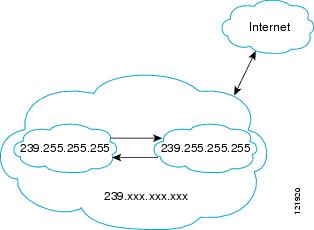
You can set up an administratively scoped boundary on an interface for multicast group addresses using the ip multicast boundary command with the access-list argument. A standard access list defines the range of addresses affected. When a boundary is set up, no multicast data packets are allowed to flow across the boundary from either direction. The boundary allows the same multicast group address to be reused in different administrative domains.
The Internet Assigned Numbers Authority (IANA) has designated the multicast address range 239.0.0.0 to 239.255.255.255 as the administratively scoped addresses. This range of addresses can be reused in domains administered by different organizations. They would be considered local, not globally unique.
You can configure the filter-autorp keyword to examine and filter Auto-RP discovery and announcement messages at the administratively scoped boundary. Any Auto-RP group range announcements from the Auto-RP packets that are denied by the boundary access control list (ACL) are removed. An Auto-RP group range announcement is permitted and passed by the boundary only if all addresses in the Auto-RP group range are permitted by the boundary ACL. If any address is not permitted, the entire group range is filtered and removed from the Auto-RP message before the Auto-RP message is forwarded.
Benefits of Auto-RP in a PIM Network
- Auto-RP allows any change to the RP designation to be configured only on the routers that are RPs, not on the leaf routers.
- Auto-RP offers the ability to scope the RP address within a domain. Scoping can be achieved by using the ip multicast boundary command with the filter-autorp keyword.
Anycast RP Overview
Anycast RP is a useful application of MSDP. Originally developed for interdomain multicast applications, MSDP used for Anycast RP is an intradomain feature that provides redundancy and load-sharing capabilities. Enterprise customers typically use Anycast RP for configuring a Protocol Independent Multicast sparse mode (PIM-SM) network to meet fault tolerance requirements within a single multicast domain.
In anycast RP, two or more RPs are configured with the same IP address on loopback interfaces. The anycast RP loopback address should be configured with a 32-bit mask, making it a host address. All the downstream routers should be configured so that the anycast RP loopback address is the IP address of their local RP. IP routing will automatically select the topologically closest RP for each source and receiver. Assuming that the sources are evenly spaced around the network, an equal number of sources will register with each RP. That is, the process of registering the sources will be shared equally by all the RPs in the network.
Because a source may register with one RP and receivers may join to a different RP, a method is needed for the RPs to exchange information about active sources. This information exchange is done with MSDP.
In anycast RP, all the RPs are configured to be MSDP peers of each other. When a source registers with one RP, an SA message will be sent to the other RPs informing them that there is an active source for a particular multicast group. The result is that each RP will know about the active sources in the area of the other RPs. If any of the RPs were to fail, IP routing would converge, and one of the RPs would become the active RP in more than one area. New sources would register with the backup RP. Receivers would join the new RP and connectivity would be maintained.
The RP is normally needed only to start new sessions with sources and receivers. The RP facilitates the shared tree so that sources and receivers can establish a direct multicast data flow. If a multicast data flow is already established between a source and the receiver, an RP failure will not affect that session. Anycast RP ensures that new sessions with sources and receivers can begin at any time.
BSR Overview
BSR Election and Functionality
PIM uses the BSR to discover and announce RP-set information for each group prefix to all the routers in a PIM domain. This is the same function performed by Auto-RP, but the BSR is part of the PIM Version 2 specification. The BSR mechanism interoperates with Auto-RP on Cisco routers.
To avoid a single point of failure, you can configure several candidate BSRs in a PIM domain. A BSR is elected among the candidate BSRs automatically; they use bootstrap messages to discover which BSR has the highest priority. This router then announces to all PIM routers in the PIM domain that it is the BSR.
Following the election of the BSR, candidate RPs use unicast to announce to the BSR their willingness to be the RP. The BSR advertises the entire group-to-RP mapping set to the router link local address 224.0.0.13. Unlike the RP mapping agent in Auto-RP, which is used by Auto-RP to select the RP, every router in the BSR network is responsible for selecting the RP.
BSR lacks the ability to scope RP advertisements; however, BSR is used when vendor interoperability or open standard adherence is a requirement.
BSR Border Interface
A border interface in a PIM sparse mode domain requires precautions to prevent exchange of certain traffic with a neighboring domain reachable through that interface, especially if that domain is also running PIM sparse mode. BSR and Auto-RP messages should not be exchanged between different domains, because routers in one domain may elect RPs in the other domain, resulting in protocol malfunction or loss of isolation between the domains. Configure a BSR border interface to prevent BSR messages from being sent or received through an interface.
Static RP Overview
If you are configuring PIM sparse mode, you must configure a PIM RP for a multicast group. An RP can either be configured statically in each device, or learned through a dynamic mechanism. This task explains how to statically configure an RP, as opposed to the router learning the RP through a dynamic mechanism such as Auto-RP.
PIM designated routers (DRs) forward data from directly connected multicast sources to the RP for distribution down the shared tree. Data is forwarded to the RP in one of two ways. It is encapsulated in register packets and unicast directly to the RP, or, if the RP has itself joined the source tree, it is multicast forwarded per the RPF forwarding algorithm. Last hop routers directly connected to receivers may, at their discretion, join themselves to the source tree and prune themselves from the shared tree.
A single RP can be configured for multiple groups that are defined by an access list. If no RP is configured for a group, the router treats the group as dense using the PIM dense mode techniques. (You can prevent this occurrence by configuring the no ip pim dm-fallbackcommand.)
If dynamic and static group-to-RP mappings are used together and there is an RP address conflict, the RP address configured for a static group-to-RP mapping (with the ip pim rp-address overridecommand) will take precedence.
 Note | If the override keyword is not specified and there is RP address conflict, dynamic group-to-RP mappings will take precedence over static group-to-RP mappings. |
SSM Overview
Source Specific Multicast (SSM). SSM is an extension of IP multicast where datagram traffic is forwarded to receivers from only those multicast sources that the receivers have explicitly joined. For multicast groups configured for SSM, only source-specific multicast distribution trees (not shared trees) are created.
- SSM Components
- How SSM Differs from Internet Standard Multicast
- SSM Operations
- IGMPv3 Host Signaling
- Benefits of Source Specific Multicast
SSM Components
SSM is a datagram delivery model that best supports one-to-many applications, also known as broadcast applications. SSM is a core networking technology for the Cisco implementation of IP multicast solutions targeted for audio and video broadcast application environments and is described in RFC 3569. The following two components together support the implementation of SSM:
- Protocol Independent Multicast source-specific mode (PIM-SSM)
- Internet Group Management Protocol Version 3 (IGMPv3)
Protocol Independent Multicast (PIM) SSM, or PIM-SSM, is the routing protocol that supports the implementation of SSM and is derived from PIM sparse mode (PIM-SM). IGMP is the Internet Engineering Task Force (IETF) standards track protocol used for hosts to signal multicast group membership to routers. IGMP Version 3 supports source filtering, which is required for SSM. IGMP For SSM to run with IGMPv3, SSM must be supported in the router, the host where the application is running, and the application itself.
How SSM Differs from Internet Standard Multicast
The standard IP multicast infrastructure in the Internet and many enterprise intranets is based on the PIM-SM protocol and Multicast Source Discovery Protocol (MSDP). These protocols have proved to be reliable, extensive, and efficient. However, they are bound to the complexity and functionality limitations of the Internet Standard Multicast (ISM) service model. For example, with ISM, the network must maintain knowledge about which hosts in the network are actively sending multicast traffic. With SSM, this information is provided by receivers through the source addresses relayed to the last-hop routers by IGMPv3. SSM is an incremental response to the issues associated with ISM and is intended to coexist in the network with the protocols developed for ISM. In general, SSM provides IP multicast service for applications that utilize SSM.
ISM service is described in RFC 1112. This service consists of the delivery of IP datagrams from any source to a group of receivers called the multicast host group. The datagram traffic for the multicast host group consists of datagrams with an arbitrary IP unicast source address S and the multicast group address G as the IP destination address. Systems will receive this traffic by becoming members of the host group. Membership in a host group simply requires signaling the host group through IGMP Version 1, 2, or 3.
In SSM, delivery of datagrams is based on (S, G) channels. Traffic for one (S, G) channel consists of datagrams with an IP unicast source address S and the multicast group address G as the IP destination address. Systems will receive this traffic by becoming members of the (S, G) channel. In both SSM and ISM, no signaling is required to become a source. However, in SSM, receivers must subscribe or unsubscribe to (S, G) channels to receive or not receive traffic from specific sources. In other words, receivers can receive traffic only from (S, G) channels to which they are subscribed, whereas in ISM, receivers need not know the IP addresses of sources from which they receive their traffic. The proposed standard approach for channel subscription signaling utilizes IGMP INCLUDE mode membership reports, which are supported only in IGMP Version 3.
SSM can coexist with the ISM service by applying the SSM delivery model to a configured subset of the IP multicast group address range. The Internet Assigned Numbers Authority (IANA) has reserved the address range from 232.0.0.0 through 232.255.255.255 for SSM applications and protocols. The software allows SSM configuration for an arbitrary subset of the IP multicast address range from 224.0.0.0 through 239.255.255.255. When an SSM range is defined, an existing IP multicast receiver application will not receive any traffic when it tries to use addresses in the SSM range unless the application is modified to use explicit (S, G) channel subscription or is SSM-enabled through a URL Rendezvous Directory (URD).
SSM Operations
An established network in which IP multicast service is based on PIM-SM can support SSM services. SSM can also be deployed alone in a network without the full range of protocols that are required for interdomain PIM-SM. That is, SSM does not require an RP, so there is no need for an RP mechanism such as Auto-RP, MSDP, or bootstrap router (BSR).
If SSM is deployed in a network that is already configured for PIM-SM, then only the last-hop routers must be upgraded to a software image that supports SSM. Routers that are not directly connected to receivers do not have to upgrade to a software image that supports SSM. In general, these non-last-hop routers must only run PIM-SM in the SSM range. They may need additional access control configuration to suppress MSDP signaling, registering, or PIM-SM shared-tree operations from occurring within the SSM range.
The SSM mode of operation is enabled by configuring the SSM range using the ip pim ssm global configuration command. This configuration has the following effects:
- For groups within the SSM range, (S, G) channel subscriptions are accepted through IGMPv3 INCLUDE mode membership reports.
- PIM operations within the SSM range of addresses change to PIM-SSM, a mode derived from PIM-SM. In this mode, only PIM (S, G) Join and Prune messages are generated by the router. Incoming messages related to rendezvous point tree (RPT) operations are ignored or rejected, and incoming PIM register messages are immediately answered with Register-Stop messages. PIM-SSM is backward-compatible with PIM-SM unless a router is a last-hop router. Therefore, routers that are not last-hop routers can run PIM-SM for SSM groups (for example, if they do not yet support SSM).
- For groups within the SSM range, no MSDP Source-Active (SA) messages within the SSM range will be accepted, generated, or forwarded.
IGMPv3 Host Signaling
IGMPv3 is the third version of the IETF standards track protocol in which hosts signal membership to last-hop routers of multicast groups. IGMPv3 introduces the ability for hosts to signal group membership that allows filtering capabilities with respect to sources. A host can signal either that it wants to receive traffic from all sources sending to a group except for some specific sources (a mode called EXCLUDE) or that it wants to receive traffic only from some specific sources sending to the group (a mode called INCLUDE).
IGMPv3 can operate with both ISM and SSM. In ISM, both EXCLUDE and INCLUDE mode reports are accepted by the last-hop router. In SSM, only INCLUDE mode reports are accepted by the last-hop router.
Benefits of Source Specific Multicast
IP Multicast Address Management Not Required
In the ISM service, applications must acquire a unique IP multicast group address because traffic distribution is based only on the IP multicast group address used. If two applications with different sources and receivers use the same IP multicast group address, then receivers of both applications will receive traffic from the senders of both applications. Even though the receivers, if programmed appropriately, can filter out the unwanted traffic, this situation would cause generally unacceptable levels of unwanted traffic.
Allocating a unique IP multicast group address for an application is still a problem. Most short-lived applications use mechanisms like Session Description Protocol (SDP) and Session Announcement Protocol (SAP) to get a random address, a solution that does not work well with a rising number of applications in the Internet. The best current solution for long-lived applications is described in RFC 2770, but this solution suffers from the restriction that each autonomous system is limited to only 255 usable IP multicast addresses.
In SSM, traffic from each source is forwarded between routers in the network independent of traffic from other sources. Thus different sources can reuse multicast group addresses in the SSM range.
Denial of Service Attacks from Unwanted Sources Inhibited
In SSM, multicast traffic from each individual source will be transported across the network only if it was requested (through IGMPv3, IGMP v3lite, or URD memberships) from a receiver. In contrast, ISM forwards traffic from any active source sending to a multicast group to all receivers requesting that multicast group. In Internet broadcast applications, this ISM behavior is highly undesirable because it allows unwanted sources to easily disturb the actual Internet broadcast source by simply sending traffic to the same multicast group. This situation depletes bandwidth at the receiver side with unwanted traffic and thus disrupts the undisturbed reception of the Internet broadcast. In SSM, this type of denial of service (DoS) attack cannot be made by simply sending traffic to a multicast group.
Easy to Install and Manage
SSM is easy to install and provision in a network because it does not require the network to maintain which active sources are sending to multicast groups. This requirement exists in ISM (with IGMPv1, IGMPv2, or IGMPv3).
The current standard solutions for ISM service are PIM-SM and MSDP. Rendezvous point (RP) management in PIM-SM (including the necessity for Auto-RP or BSR) and MSDP is required only for the network to learn about active sources. This management is not necessary in SSM, which makes SSM easier than ISM to install and manage, and therefore easier than ISM to operationally scale in deployment. Another factor that contributes to the ease of installation of SSM is the fact that it can leverage preexisting PIM-SM networks and requires only the upgrade of last hop routers to support IGMPv3, IGMP v3lite, or URD.
Ideal for Internet Broadcast Applications
The three benefits previously described make SSM ideal for Internet broadcast-style applications for the following reasons:
- The ability to provide Internet broadcast services through SSM without the need for unique IP multicast addresses allows content providers to easily offer their service (IP multicast address allocation has been a serious problem for content providers in the past).
- The prevention against DoS attacks is an important factor for Internet broadcast services because, with their exposure to a large number of receivers, they are the most common targets for such attacks.
- The ease of installation and operation of SSM makes it ideal for network operators, especially in those cases where content needs to be forwarded between multiple independent PIM domains (because there is no need to manage MSDP for SSM between PIM domains).
Bidir-PIM Overview
Bidir-PIM shares many of its shortest path tree (SPT) operations with PIM-SM. Bidir-PIM also has unconditional forwarding of source traffic toward the RP upstream on the shared tree, but has no registering process for sources as in PIM-SM. These modifications allow forwarding of traffic in all routers based solely on the (*, G) multicast routing entries. This form of forwarding eliminates any source-specific state and allows scaling capability to an arbitrary number of sources.
- Multicast Group Modes
- Bidirectional Shared Tree
- DF Election
- Bidirectional Group Tree Building
- Packet Forwarding
- Benefits of Bidirectional PIM
Multicast Group Modes
In PIM, packet traffic for a multicast group is routed according to the rules of the mode configured for that multicast group. The Cisco implementation of PIM supports four modes for a multicast group:
- PIM bidirectional mode
- PIM dense mode
- PIM sparse mode
- PIM Source Specific Mode (SSM)
A router can simultaneously support all four modes or any combination of them for different multicast groups.
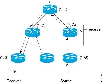
Bidirectional Shared Tree
In bidirectional mode, traffic is routed only along a bidirectional shared tree that is rooted at the rendezvous point (RP) for the group. In bidir-PIM, the IP address of the RP acts as the key to having all routers establish a loop-free spanning tree topology rooted in that IP address. This IP address need not be a router, but can be any unassigned IP address on a network that is reachable throughout the PIM domain. This technique is the preferred configuration method for establishing a redundant RP configuration for bidir-PIM.
Membership in a bidirectional group is signaled by way of explicit Join messages. Traffic from sources is unconditionally sent up the shared tree toward the RP and passed down the tree toward the receivers on each branch of the tree.
The figures below show the difference in state created per router for a unidirectional shared tree and source tree versus a bidirectional shared tree.
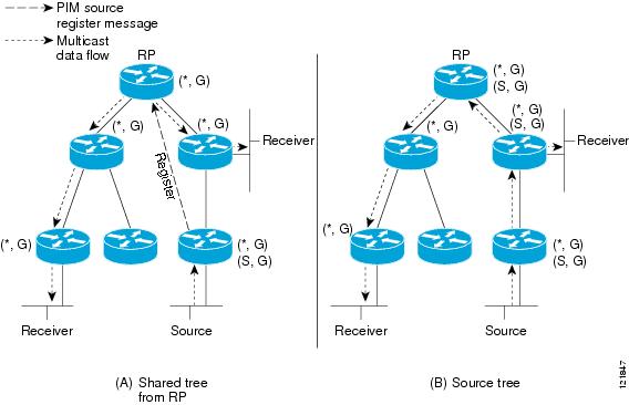
For packets that are forwarded downstream from the RP toward receivers, there are no fundamental differences between bidir-PIM and PIM-SM. Bidir-PIM deviates substantially from PIM-SM for traffic that is passed from sources upstream toward the RP.
PIM-SM cannot forward traffic in the upstream direction of a tree because it accepts traffic from only one Reverse Path Forwarding (RPF) interface. This interface (for the shared tree) points toward the RP, thus allowing only downstream traffic flow. Upstream traffic is first encapsulated into unicast register messages, which are passed from the designated router (DR) of the source toward the RP. Second, the RP joins an SPT that is rooted at the source. Therefore, in PIM-SM, traffic from sources destined for the RP does not flow upstream in the shared tree, but downstream along the SPT of the source until it reaches the RP. From the RP, traffic flows along the shared tree toward all receivers.
In bidir-PIM, the packet-forwarding rules have been improved over PIM-SM, allowing traffic to be passed up the shared tree toward the RP. To avoid multicast packet looping, bidir-PIM introduces a new mechanism called designated forwarder (DF) election, which establishes a loop-free SPT rooted at the RP.
DF Election
On every network segment and point-to-point link, all PIM routers participate in a procedure called designated forwarder (DF) election. The procedure selects one router as the DF for every RP of bidirectional groups. This router is responsible for forwarding multicast packets received on that network.
The DF election is based on unicast routing metrics. The router with the most preferred unicast routing metric to the RP becomes the DF. Use of this method ensures that only one copy of every packet will be sent to the RP, even if there are parallel equal-cost paths to the RP.
A DF is selected for every RP of bidirectional groups. As a result, multiple routers may be elected as DF on any network segment, one for each RP. Any particular router may be elected as DF on more than one interface.
Bidirectional Group Tree Building
The procedure for joining the shared tree of a bidirectional group is almost identical to that used in PIM-SM. One main difference is that, for bidirectional groups, the role of the DR is assumed by the DF for the RP.
On a network that has local receivers, only the router elected as the DF populates the outgoing interface list (olist) upon receiving Internet Group Management Protocol (IGMP) Join messages, and sends (*, G) Join and Leave messages upstream toward the RP. When a downstream router wishes to join the shared tree, the RPF neighbor in the PIM Join and Leave messages is always the DF elected for the interface that lead to the RP.
When a router receives a Join or Leave message, and the router is not the DF for the receiving interface, the message is ignored. Otherwise, the router updates the shared tree in the same way as in sparse mode.
In a network where all routers support bidirectional shared trees, (S, G) Join and Leave messages are ignored. There is also no need to send PIM assert messages because the DF election procedure eliminates parallel downstream paths from any RP. An RP never joins a path back to the source, nor will it send any register stops.
Packet Forwarding
A router creates (*, G) entries only for bidirectional groups. The olist of a (*, G) entry includes all the interfaces for which the router has been elected DF and that have received either an IGMP or PIM Join message. If a router is located on a sender-only branch, it will also create a (*, G) state, but the olist will not include any interfaces.
If a packet is received from the RPF interface toward the RP, the packet is forwarded downstream according to the olist of the (*, G) entry. Otherwise, only the router that is the DF for the receiving interface forwards the packet upstream toward the RP; all other routers must discard the packet.
Benefits of Bidirectional PIM
- Bidir-PIM removes the performance cost of maintaining a routing state table for a large number of sources.
- Bidir-PIM is designed to be used for many-to-many applications within individual PIM domains. Multicast groups in bidirectional PIM mode can scale to an arbitrary number of sources without incurring overhead due to the number of sources.
How to Configure Basic IP Multicast
The tasks described in this section configure the basic IP multicast modes. No single task in this section is required; however, at least one of the tasks must be performed to configure IP multicast in a network. More than one of the tasks may be needed.
- Configuring Sparse Mode with Auto-RP
- Configuring Sparse Mode with Anycast RP
- Configuring Sparse Mode with a Bootstrap Router
- Configuring Sparse Mode with a Single Static RP
- Configuring Source Specific Multicast
- Configuring Bidirectional PIM
Configuring Sparse Mode with Auto-RP
This section contains information about and instructions on how to configure auto-rendezvous point (Auto-RP). Auto-RP can also be optionally used with anycast RP.
Note | The simultaneous deployment of Auto-RP and bootstrap router (BSR) is not supported. |
- When configuring Auto-RP, you must either configure the Auto-RP listener feature using the ip pim autorp listener command (Step 5) and specify sparse mode using the ip pim sparse-mode command (Step 7) or specify sparse-dense mode (Step 8) using the ip pim sparse-dense mode command.
Note | When you configure sparse-dense mode, dense mode failover may result in a network dense-mode flood. To avoid this condition, use PIM sparse mode with the Auto-RP listener feature. |
- An interface configured in sparse-dense mode is treated in either sparse mode or dense mode of operation, depending on the mode in which the multicast group operates. You must decide how to configure your interfaces.
- All access lists that are needed when Auto-RP is configured should be configured prior to beginning the configuration task. For information about how to configure an access list, see the " Creating an IP Access List and Applying It to an Interface " module.
- If a group has no known RP and the interface is configured to be sparse-dense mode, the interface is treated as if it were in dense mode, and data is flooded over the interface. To avoid this data flooding, configure the Auto-RP listener using the ip pim autorp listener command and then configure the interface as sparse mode using the ip pim sparse mode command.
DETAILED STEPS
Configuring Sparse Mode with Anycast RP
This section describes how to configure sparse mode with anycast RP for RP redundancy.
Anycast RPs are configured statically, and interfaces are configured to operate in Protocol Independent Multicast-Sparse Mode (PIM-SM). In an anycast RP configuration, two or more RPs are configured with the same IP address on loopback interfaces. The Anycast RP loopback address should be configured with a 32-bit mask, making it a host address. An Anycast RP configuration is easy to configure and troubleshoot because the same host address is used as the RP address regardless of which router it is configured on.
Anycast RP allows two or more rendezvous points (RPs) to share the load for source registration and have the ability to act as hot backup routers for each other. Multicast Source Discovery Protocol (MSDP) is the key protocol that makes anycast RP possible.
DETAILED STEPS
| Command or Action | Purpose | |
|---|---|---|
Step 1 |
enable
Example: Router> enable |
Enables privileged EXEC mode. |
Step 2 |
configure
terminal
Example: Router# configure terminal |
Enters global configuration mode. |
Step 3 |
ip
multicast-routing
[distributed]
Example: Router(config)# ip multicast-routing |
Enables IP multicast routing. |
Step 4 |
interface
type
number
Example: Router(config)# interface gigabitethernet 1/0/0 |
Selects an interface that is connected to hosts on which PIM can be enabled. |
Step 5 |
ip
pim
sparse-mode
Example: Router(config-if)# ip pim sparse-mode |
Enables sparse mode. |
Step 6 |
ip
pim
rp-address
rp-address
Example: Router(config-if)# ip pim rp-address 10.0.0.1 |
Configures the address of a PIM RP for a particular group. |
Step 7 | Repeat Steps 1 through 6 on two or more routers assigning the
same RP address to each.
|
-- |
Step 8 |
interface
loopback
[interface-number]
ip address
[ip-address] [mask]
Example: Router(config-if)# interface loopback 0 Example: ip address 10.0.0.1 255.255.255.255 |
Configures the interface loopback IP address for the RP router. |
Step 9 |
interface
loopback
[interface-number]
ip address
[ip-address] [mask]
Example: Router(config-if)# interface loopback 1 Example: ip address 10.1.1.1 255.255.255.255 |
Configures the interface loopback IP address for MSDP peering. |
Step 10 |
exit
Example: Router(config-if)# exit |
Exits interface configuration mode and returns to global configuration mode. |
Step 11 |
ip
msdp
peer
{peer-name |
peer-address}
[connect-source interface-type interface-number]
[remote-as as-number]
Example: Router(config)# ip msdp peer 10.1.1.2 connect-source loopback 1 |
Configures an MSDP peer. |
Step 12 |
ip
msdp
originator-id
loopback
[interface]
Example: Router(config)# ip msdp originator-id loopback 1 |
Allows an MSDP speaker that originates a SA message to use the IP address of the interface as the RP address in the SA message. |
Step 13 | Repeat Steps 8 through 12 on the redundant RPs.
|
-- |
Configuring Sparse Mode with a Bootstrap Router
This section describes how to configure a bootstrap router (BSR), which provides a fault-tolerant, automated RP discovery and distribution mechanism so that routers learn the group-to-RP mappings dynamically.
Note | The simultaneous deployment of Auto-RP and BSR is not supported. |
DETAILED STEPS
| Command or Action | Purpose | |||||
|---|---|---|---|---|---|---|
Step 1 |
enable
Example: Router> enable |
Enables privileged EXEC mode.
| ||||
Step 2 |
configure
terminal
Example: Router# configure terminal |
Enters global configuration mode. | ||||
Step 3 |
ip
multicast-routing
[distributed] Example: Router(config)# ip multicast-routing |
Enables IP multicast routing.
| ||||
Step 4 |
interface
type
number
Example: Router(config)# interface gigabitethernet 1/0/0 |
Selects an interface that is connected to hosts on which PIM can be enabled. | ||||
Step 5 |
ip
pim
sparse-mode
Example: Router(config-if)# ip pim sparse-mode |
Enables sparse mode. | ||||
Step 6 |
end
Example: Router(config-if)# end |
Returns to global configuration mode. | ||||
Step 7 |
Repeat Steps 1 through 6 on every multicast-enabled interface on every router. |
-- | ||||
Step 8 |
ip
pim
bsr-candidate
interface-type
interface-number
[hash-mask-length [priority]] Example: Router(config)# ip pim bsr-candidate gigibitethernet 0/0/0 0 192 |
Configures the router to announce its candidacy as a bootstrap router (BSR).
| ||||
Step 9 |
ip
pim
rp-candidate
interface-type
interface-number
[group-list access-list] [interval seconds] [priority value] Example: Router(config)# ip pim rp-candidate gigabitethernet 2/0/0 group-list 4 priority 192 |
Configures the router to advertise itself as a PIM Version 2 candidate RP to the BSR.
| ||||
Step 10 |
Repeat Steps 8 through 10 on all RP and BSR routers. |
-- | ||||
Step 11 |
interface
type
number
Example: Router(config)# interface gigabitethernet 1/0/0 |
Selects an interface that is connected to hosts on which PIM can be enabled. | ||||
Step 12 |
ip
pim
bsr-border
Example: Router(config-if)# ip pim bsr-border |
Prevents the bootstrap router (BSR) messages from being sent or received through an interface.
| ||||
Step 13 |
end
Example: Router(config-if)# end |
Ends the current configuration session and returns to privileged EXEC mode. | ||||
Step 14 |
Repeat Steps 11 through 13 on all the routers that have boundary interfaces where the messages should not be sent or received. |
-- | ||||
Step 15 |
show
ip
pim
rp
[mapping] [rp-address] Example: Router# show ip pim rp |
(Optional) Displays active rendezvous points (RPs) that are cached with associated multicast routing entries. | ||||
Step 16 |
show
ip
pim
rp-hash
[group-address] [group-name] Example: Router# show ip pim rp-hash 239.1.1.1 |
(Optional) Displays which rendezvous point (RP) is being selected for a specified group. | ||||
Step 17 |
show
ip
pim
bsr-router
Example: Router# show ip pim bsr-router |
(Optional) Displays the bootstrap router (BSR) information. | ||||
Step 18 |
show
ip
igmp
groups
[group-name | group-address| interface-type interface-number] [detail] Example: Router# show ip igmp groups |
(Optional) Displays the multicast groups having receivers that are directly connected to the router and that were learned through IGMP.
| ||||
Step 19 |
show
ip
mroute
Example: Router# show ip mroute cbone-audio |
(Optional) Displays the contents of the IP mroute table. |
Configuring Sparse Mode with a Single Static RP
A rendezvous point (RP) is required in networks running Protocol Independent Multicast sparse mode (PIM-SM). In PIM-SM, traffic will be forwarded only to network segments with active receivers that have explicitly requested multicast data.
This section describes how to configure sparse mode with a single static RP.
All access lists that are needed when sparse mode is configured with a single static RP should be configured prior to beginning the configuration task.
Note | The same RP address cannot be used for both bidirectional and sparse mode PIM groups. |
DETAILED STEPS
| Command or Action | Purpose | |||||
|---|---|---|---|---|---|---|
Step 1 |
enable
Example: Router> enable |
Enables privileged EXEC mode. | ||||
Step 2 |
configure
terminal
Example: Router# configure terminal |
Enters global configuration mode. | ||||
Step 3 |
ip
multicast-routing
[distributed]
Example: Router(config)# ip multicast-routing |
Enables IP multicast routing. | ||||
Step 4 |
interface
type
number
Example: Router(config)# interface gigabitethernet 1/0/0 |
Selects an interface that is connected to hosts on which PIM can be enabled. | ||||
Step 5 |
ip
pim
sparse-mode
Example: Router(config-if)# ip pim sparse-mode |
Enables PIM on an interface. You must use sparse mode. | ||||
Step 6 | Repeat Steps 1 through 5 on every interface that uses IP multicast.
|
-- | ||||
Step 7 |
exit
Example: Router(config-if)# exit |
Returns to global configuration mode. | ||||
Step 8 |
ip
pim
rp-address
rp-address
[access-list] [override]
Example: Router(config)# ip pim rp-address 192.168.0.0 |
Configures the address of a PIM RP for a particular group.
| ||||
Step 9 |
end
Example: Router(config)# end |
Ends the current configuration session and returns to EXEC mode. | ||||
Step 10 |
show
ip
pim
rp
[mapping] [rp-address]
Example: Router# show ip pim rp mapping |
(Optional) Displays RPs known in the network and shows how the router learned about each RP. | ||||
Step 11 |
show
ip
igmp
groups
[group-name |
group-address|
interface-type
interface-number] [detail]
Example: Router# show ip igmp groups |
(Optional) Displays the multicast groups having receivers that are directly connected to the router and that were learned through IGMP. | ||||
Step 12 |
show
ip
mroute
Example: Router# show ip mroute |
(Optional) Displays the contents of the IP mroute table. |
Configuring Source Specific Multicast
If you want to use an access list to define the SSM range, configure the access list before you reference the access list in the ip pim ssm command.
DETAILED STEPS
| Command or Action | Purpose | |
|---|---|---|
Step 1 |
enable
Example: Router> enable |
Enables privileged EXEC mode. |
Step 2 |
configure
terminal
Example: Router# configure terminal |
Enters global configuration mode. |
Step 3 |
ip
multicast-routing
[distributed]
Example: Router(config)# ip multicast-routing |
Enables IP multicast routing. |
Step 4 |
ip
pim
ssm
{default |
range
access-list}
Example: Router(config)# ip pim ssm default |
Configures SSM service. |
Step 5 |
interface
type
number
Example: Router(config)# interface gigabitethernet 1/0/0 |
Selects an interface that is connected to hosts on which IGMPv3 can be enabled. |
Step 6 |
ip
pim
sparse-mode
Example: Router(config-if)# ip pim sparse-mode |
Enables PIM on an interface. You must use sparse mode. |
Step 7 | Repeat Steps 1 through 6 on every interface that uses IP multicast.
|
-- |
Step 8 |
ip
igmp
version
3
Example: Router(config-if)# ip igmp version 3 |
Enables IGMPv3 on this interface. The default version of IGMP is set to Version 2. Version 3 is required by SSM. |
Step 9 | Repeat Step 8 on all host-facing interfaces.
|
-- |
Step 10 |
end
Example: Router(config-if)# end |
Ends the current configuration session and returns to privileged EXEC mode. |
Step 11 |
show
ip
igmp
groups
[group-name |
group-address|
interface-type
interface-number] [detail]
Example: Router# show ip igmp groups |
(Optional) Displays the multicast groups having receivers that are directly connected to the router and that were learned through IGMP. |
Step 12 |
show
ip
mroute
Example: Router# show ip mroute |
(Optional) Displays the contents of the IP mroute table. |
Configuring Bidirectional PIM
All access lists needed when configuring bidirectional PIM must be configured prior to beginning the configuration task.
DETAILED STEPS
| Command or Action | Purpose | |||
|---|---|---|---|---|
Step 1 |
enable
Example: Router> enable |
Enables privileged EXEC mode.
| ||
Step 2 |
configure
terminal
Example: Router# configure terminal |
Enters global configuration mode. | ||
Step 3 |
ip
multicast-routing
[distributed] Example: Router(config)# ip multicast-routing |
Enables IP multicast routing.
| ||
Step 4 |
interface
type
number
Example: Router(config)# interface gigabitethernet 1/0/0 |
Selects an interface that is connected to hosts on which PIM can be enabled. | ||
Step 5 |
ip
pim
sparse-mode
Example: Router(config-if)# ip pim sparse-mode |
Enables sparse mode. | ||
Step 6 |
exit
Example: Router(config-if)# exit |
Returns to global configuration mode. | ||
Step 7 |
ip
pim
bidir-enable
Example: Router(config)# ip pim bidir-enable |
Enables bidir-PIM on a router.
| ||
Step 8 |
ip
pim
rp-address
rp-address
[access-list] [override] bidir Example: Router(config)# ip pim rp-address 10.0.1.1 45 bidir |
Configures the address of a PIM RP for a particular group.
| ||
Step 9 |
end
Example: Router(config-if)# end |
Exits interface configuration mode and returns to privileged EXEC mode. | ||
Step 10 |
Repeat Steps 2 through 9 on every multicast-enabled interface on every router. |
-- | ||
Step 11 |
show
ip
pim
rp
[mapping] [rp-address] Example: Router# show ip pim rp |
(Optional) Displays active RPs that are cached with associated multicast routing entries. | ||
Step 12 |
show
ip
mroute
Example: Router# show ip mroute |
(Optional) Displays the contents of the IP mroute table. | ||
Step 13 |
show
ip
pim
interface
[type number] [df | count] [rp-address] Example: Router# show ip pim interface |
(Optional) Displays information about the elected DF for each RP of an interface, along with the unicast routing metric associated with the DF. |
Configuration Examples for Basic IP Multicast
- Sparse Mode with Auto-RP Example
- Sparse Mode with Anycast RP Example
- Sparse Mode with Bootstrap Router Example
- BSR and RFC 2362 Interoperable Candidate RP Example
- Example: Sparse Mode with a Single Static RP
- SSM with IGMPv3 Example
- SSM Filtering Example
- Bidir-PIM Example
Sparse Mode with Auto-RP Example
The following example configures sparse mode with Auto-RP:
ip multicast-routing
ip pim autorp listener
ip pim send-rp-announce Loopback0 scope 16 group-list 1
ip pim send-rp-discovery Loopback1 scope 16
no ip pim dm-fallback
access-list 1 permit 239.254.2.0 0.0.0.255
access-list 1 permit 239.254.3.0 0.0.0.255
.
.
.
access-list 10 permit 224.0.1.39
access-list 10 permit 224.0.1.40
access-list 10 permit 239.254.2.0 0.0.0.255
access-list 10 permit 239.254.3.0 0.0.0.255
Sparse Mode with Anycast RP Example
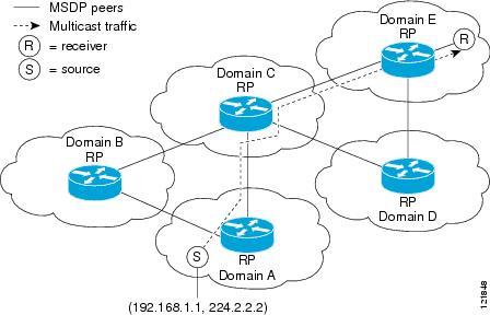
The main purpose of an Anycast RP implementation is that the downstream multicast routers will have just one address for an RP. The example given in the figure below shows how loopback interface 0 of the RPs (RP1 and RP2) is configured with the 10.0.0.1 IP address. If this 10.0.0.1 address is configured on all RPs as the address for loopback interface 0 and then configured as the RP address, IP routing will converge on the closest RP. This address must be a host route; note the 255.255.255.255 subnet mask.
The downstream routers must be informed about the 10.0.0.1 RP address. In the figure below, the routers are configured statically with the ip pim rp-address 10.0.0.1global configuration command. This configuration could also be accomplished using the Auto-RP or bootstrap router (BSR) features.
The RPs in the figure must also share source information using MSDP. In this example, loopback interface 1 of the RPs (RP1 and RP2) is configured for MSDP peering. The MSDP peering address must be different from the anycast RP address.
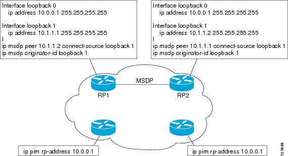
Many routing protocols choose the highest IP address on loopback interfaces for the router ID. A problem may arise if the router selects the anycast RP address for the router ID. It is recommended that you avoid this problem by manually setting the router ID on the RPs to the same address as the MSDP peering address (for example, the loopback 1 address in the figure above). In Open Shortest Path First (OSPF), the router ID is configured using the router-idrouter configuration command. In Border Gateway Protocol (BGP), the router ID is configured using the bgp router-id router configuration command. In many BGP topologies, the MSDP peering address and the BGP peering address must be the same in order to pass the RPF check. The BGP peering address can be set using the neighbor update-source router configuration command.
The anycast RP example above uses IP addresses taken from RFC 1918. These IP addresses are normally blocked at interdomain borders and therefore are not accessible to other ISPs. You must use valid IP addresses if you want the RPs to be reachable from other domains.
The following example shows how to perform an Anycast RP configuration.
On RP 1
ip pim rp-address 10.0.0.1
interface loopback 0
 ip address 10.0.0.1 255.255.255.255
!
interface loopback 1
 ip address 10.1.1.1. 255.255.255.255
!
 ip msdp peer 10.1.1.2 connect-source loopback 1
 ip msdp originator-id loopback 1
Sparse Mode with Bootstrap Router Example
The following example is a configuration for a candidate BSR, which also happens to be a candidate RP:
!
ip multicast-routing
!
interface GigabitEthernet0/0/0
 ip address 172.69.62.35 255.255.255.240
 ip pim sparse-mode
!
interface GigabitEthernet1/0/0
 ip address 172.21.24.18 255.255.255.248
 ip pim sparse-mode
!
interface GigabitEthernet2/0/0
 ip address 172.21.24.12 255.255.255.248
 ip pim sparse-mode
!
ip pim bsr-candidate GigabitEthernet2/0/0 30 10
ip pim rp-candidate GigabitEthernet2/0/0 group-list 5
access-list 5 permit 239.255.2.0 0.0.0.255
BSR and RFC 2362 Interoperable Candidate RP Example
When Cisco and non-Cisco routers are being operated in a single PIM domain with PIM Version 2 BSR, care must be taken when configuring candidate RPs because the Cisco implementation of the BSR RP selection is not fully compatible with RFC 2362.
RFC 2362 specifies that the BSR RP be selected as follows (RFC 2362, 3.7):
- Select the candidate RP with the highest priority (lowest configured priority value).
- If there is a tie in the priority level, select the candidate RP with the highest hash function value.
- If there is a tie in the hash function value, select the candidate RP with the highest IP address.
Cisco routers always select the candidate RP based on the longest match on the announced group address prefix before selecting an RP based on priority, hash function, or IP address.
Inconsistent candidate RP selection between Cisco and non-Cisco RFC 2362-compliant routers in the same domain if multiple candidate RPs with partially overlapping group address ranges are configured can occur. Inconsistent candidate RP selection can prevent connectivity between sources and receivers in the PIM domain. A source may register with one candidate RP and a receiver may connect to a different candidate RP even though it is in the same group.
The following example shows a configuration that can cause inconsistent RP selection between a Cisco and a non-Cisco router in a single PIM domain with PIM Version 2 BSR:
access-list 10 permit 224.0.0.0  7.255.255.255
ip pim rp-candidate gigabitethernet1/0/0 group-list 10 priority 20
access-list 20 permit 224.0.0.0 15.255.255.255
ip pim rp-candidate gigabitethernet2/0/0 group-list 20 priority 10
In this example, a candidate RP on GigabitEthernet interface 1/0/0 announces a longer group prefix of 224.0.0.0/5 with a lower priority of 20. The candidate RP on GigabitEthernet interface 2/0/0 announces a shorter group prefix of 224.0.0.0/4 with a higher priority of 10. For all groups that match both ranges a Cisco router will always select the candidate RP on Ethernet interface 1 because it has the longer announced group prefix. A non-Cisco fully RFC 2362-compliant router will always select the candidate RP on GigabitEthernet interface 2/0/0 because it is configured with a higher priority.
To avoid this interoperability issue, do not configure different candidate RPs to announce partially overlapping group address prefixes. Configure any group prefixes that you want to announce from more than one candidate RP with the same group prefix length.
The following example shows how to configure the previous example so that there is no incompatibility between a Cisco router and a non-Cisco router in a single PIM domain with PIM Version 2 BSR:
access-list 10 permit 224.0.0.0  7.255.255.255
ip pim rp-candidate gigabitethernet1/0/0 group-list 10 priority 20
access-list 20 permit 224.0.0.0  7.255.255.255
access-list 20 permit 232.0.0.0  7.255.255.255
ip pim rp-candidate gigabitethernet2/0/0 group-list 20 priority 10
In this configuration the candidate RP on Ethernet interface 2 announces group address 224.0.0.0/5 and 232.0.0.0/5 which equal 224.0.0.0/4, but gives the interface the same group prefix length (5) as the candidate RP on Ethernet 1. As a result, both a Cisco router and an RFC 2362-compliant router will select the RP Ethernet interface 2.
Example: Sparse Mode with a Single Static RP
The following example sets the PIM RP address to 192.168.1.1 for all multicast groups and defines all groups to operate in sparse mode:
ip multicast-routing
interface gigiabitethernet 1/0/0
 ip pim sparse-mode
ip pim rp-address 192.168.1.1
Note | The same RP cannot be used for both bidirectional and sparse mode groups. |
The following example sets the PIM RP address to 172.16.1.1 for the multicast group 225.2.2.2 only:
access list 1 225.2.2.2 0.0.0.0
 ip pim rp-address 172.17.1.1
SSM with IGMPv3 Example
The following example shows how to configure a router (running IGMPv3) for SSM:
ip multicast-routing
!
interface GigabitEthernet3/1/0
 ip address 172.21.200.203 255.255.255.0
 description backbone interface
	ip pim sparse-mode
!
interface GigabitEthernet3/2/0
	ip address 131.108.1.2 255.255.255.0
	ip pim sparse-mode
	description ethernet connected to hosts
	ip igmp version 3
!
ip pim ssm default
SSM Filtering Example
The following example shows how to configure filtering on legacy RP routers running software releases that do not support SSM routing. This filtering will suppress all unwanted PIM-SM and MSDP traffic in the SSM range. Without this filtering, SSM will still operate, but there may be additional RPT traffic if legacy first hop and last hop routers exist in the network.
ip access-list extended  no-ssm-range
  deny   ip any 232.0.0.0 0.255.255.255 ! SSM range
  permit ip any any
! Deny registering in SSM range
ip pim accept-register list no-ssm-range
ip access-list extended msdp-nono-list
  deny   ip any 232.0.0.0 0.255.255.255 ! SSM Range
  ! .
  ! .
  ! .
  ! See ftp://ftpeng.cisco.com/ipmulticast/config-notes/msdp-sa-filter.txt for other SA
  ! messages that typically need to be filtered.
  permit ip any any
! Filter generated SA messages in SSM range. This configuration is only needed if there
! are directly connected sources to this router. The "ip pim accept-register" command
! filters remote sources.
ip msdp redistribute list msdp-nono-list
! Filter received SA messages in SSM range. "Filtered on receipt" means messages are
! neither processed or forwarded. Needs to be configured for each MSDP peer.
ip msdp sa-filter in msdp-peer1 list msdp-nono-list
! .
! .
! .
ip msdp sa-filter in msdp-peerN list msdp-nono-list
Bidir-PIM Example
By default, a bidirectional RP advertises all groups as bidirectional. An access list on the RP can be used to specify a list of groups to be advertised as bidirectional. Groups with the deny keyword will operate in dense mode. A different, nonbidirectional RP address is required for groups that operate in sparse mode because a single access list only allows either a permit or deny keyword.
The following example shows how to configure an RP for both sparse mode and bidirectional mode groups. The groups identified as 224/8 and 227/8 are bidirectional groups, and 226/8 is a sparse mode group. The RP must be configured to use different IP addresses for the sparse mode and bidirectional mode operations. Two loopback interfaces are used to allow this configuration. The addresses of these loopback interfaces must be routed throughout the PIM domain in such a way that the other routers in the PIM domain can communicate with the RP.
ip multicast-routing
!
.
.
.
!
interface loopback 0
 description One loopback address for this router's Bidir Mode RP function
 ip address 10.0.1.1 255.255.255.0
!
interface loopback 1
description One loopback address for this router's Sparse Mode RP function
 ip address 10.0.2.1 255.255.255.0
!
.
.
.
!
ip pim bidir-enable
ip pim rp-address 10.0.1.1 45 bidir
ip pim rp-address 10.0.2.1 46
!
access-list 45 permit 224.0.0.0 0.255.255.255
access-list 45 permit 227.0.0.0 0.255.255.255
access-list 46 permit 226.0.0.0 0.255.255.255
Additional References
Standards and RFCs
MIBs
Technical Assistance
|
Description |
Link |
|---|---|
|
The Cisco Support and Documentation website provides online resources to download documentation, software, and tools. Use these resources to install and configure the software and to troubleshoot and resolve technical issues with Cisco products and technologies. Access to most tools on the Cisco Support and Documentation website requires a Cisco.com user ID and password. |
Feature Information for Configuring Basic IP Multicast in IPv4 Networks
The following table provides release information about the feature or features described in this module. This table lists only the software release that introduced support for a given feature in a given software release train. Unless noted otherwise, subsequent releases of that software release train also support that feature.
Use Cisco Feature Navigator to find information about platform support and Cisco software image support. To access Cisco Feature Navigator, go to www.cisco.com/go/cfn. An account on Cisco.com is not required.
| Table 1 | Feature Information for Configuring Basic IP Multicast in IPv4 Networks |
|
Feature Name |
Releases |
Feature Information |
|---|---|---|
|
Auto RP Enhancements |
Cisco IOS XE Release 2.1 |
Auto-RP automates the distribution of group-to-rendezvous point (RP) mappings in a PIM network. To make Auto-RP work, a router must be designated as an RP mapping agent, which receives the RP announcement messages from the RPs and arbitrates conflicts. |
|
Bidirectional PIM |
Cisco IOS XE Release 2.2 |
Bidirectional PIM is an extension to the PIM suite of protocols that implements shared sparse trees with bidirectional data flow. In contrast to PIM-Sparse Mode, Bidirectional PIM avoids keeping source-specific state in a router and allows trees to scale to an arbitrary number of sources. |
|
PIM Dense Mode Fallback Prevention in a Network Following RP Information Loss |
12.3(4)T 12.0(28)S 12.2(33)SRA 12.2(33)SXH Cisco IOS XE Release 2.1 15.0(1)S |
The PIM Dense Mode Fallback Prevention in a Network Following RP Information Loss feature enables you to prevent PIM-DM fallback when all RPs fail. Preventing the use of dense mode is very important to multicast networks whose reliability is critical. This feature provides a mechanism to keep the multicast groups in sparse mode, thereby preventing dense mode flooding. The following command was introduced by this feature: ip pim dm-fallback. |
|
Source Specific Multicast (SSM) |
12.3(4)T 12.2(25)S 12.0(28)S 12.2(33)SXH 12.2(33)SRA 15.0(1)S Cisco IOS XE Release 2.1 Cisco IOS XE 3.1.0SG |
SSM is an extension of IP multicast where datagram traffic is forwarded to receivers from only those multicast sources that the receivers have explicitly joined. For multicast groups configured for SSM, only source-specific multicast distribution trees (not shared trees) are created. |
Cisco and the Cisco logo are trademarks or registered trademarks of Cisco and/or its affiliates in the U.S. and other countries. To view a list of Cisco trademarks, go to this URL: www.cisco.com/go/trademarks. Third-party trademarks mentioned are the property of their respective owners. The use of the word partner does not imply a partnership relationship between Cisco and any other company. (1110R)
Any Internet Protocol (IP) addresses and phone numbers used in this document are not intended to be actual addresses and phone numbers. Any examples, command display output, network topology diagrams, and other figures included in the document are shown for illustrative purposes only. Any use of actual IP addresses or phone numbers in illustrative content is unintentional and coincidental.