
 Feedback
Contents
- Configuring Multicast VPN
- Finding Feature Information
- Prerequisites for Configuring Multicast VPN
- Restrictions for Configuring Multicast VPN
- Information About Configuring Multicast VPN
- Multicast VPN Operation
- Benefits of Multicast VPN
- Multicast VPN Routing and Forwarding and Multicast Domains
- Multicast Distribution Trees
- Multicast Tunnel Interface
- Multicast Distributed Switching Support for Multicast VPN
- MDT Address Family in BGP for Multicast VPN
- BGP Advertisement Methods for Multicast VPN Support
- BGP Extended Community
- BGP MDT SAFI
- Automigration to the MDT SAFI
- Guidelines for Configuring the MDT SAFI
- Guidelines for Upgrading a Network to Support the MDT SAFI
- Supported Policy
- How to Configure Multicast VPN
- Configuring a Default MDT Group for a VRF
- Configuring the MDT Address Family in BGP for Multicast VPN
- Configuring the Data Multicast Group
- Configuring Multicast Routes and Information
- Verifying Information for the MDT Default Group
- Configuration Examples for Multicast VPN
- Configuring MVPN and SSM Example
- Enabling a VPN for Multicast Routing Example
- Configuring the MDT Address Family in BGP for Multicast VPN Example
- Configuring the Multicast Group Address Range for Data MDT Groups Example
- Limiting the Number of Multicast Routes Example
- Additional References
- Feature Information for Configuring Multicast VPN
Configuring Multicast VPN
The Multicast VPN (MVPN) feature provides the ability to support multicast over a Layer 3 Virtual Private Network (VPN). As enterprises extend the reach of their multicast applications, service providers can accommodate these enterprises over their Multiprotocol Label Switching (MPLS) core network. IP multicast is used to stream video, voice, and data to an MPLS VPN network core.
Historically, point-to-point tunnels were the only way to connect through a service provider network. Although such tunneled networks tend to have scalability issues, they represented the only means of passing IP multicast traffic through a VPN.
Because Layer 3 VPNs support only unicast traffic connectivity, deploying in conjunction with a Layer 3 VPN allows service providers to offer both unicast and multicast connectivity to Layer 3 VPN customers.
- Finding Feature Information
- Prerequisites for Configuring Multicast VPN
- Restrictions for Configuring Multicast VPN
- Information About Configuring Multicast VPN
- How to Configure Multicast VPN
- Configuration Examples for Multicast VPN
- Additional References
- Feature Information for Configuring Multicast VPN
Finding Feature Information
Your software release may not support all the features documented in this module. For the latest feature information and caveats, see the release notes for your platform and software release. To find information about the features documented in this module, and to see a list of the releases in which each feature is supported, see the Feature Information Table at the end of this document.
Use Cisco Feature Navigator to find information about platform support and Cisco software image support. To access Cisco Feature Navigator, go to www.cisco.com/go/cfn. An account on Cisco.com is not required.
Prerequisites for Configuring Multicast VPN
- Before performing the tasks in this module, you should be familiar with the concepts described in the " IP Multicast Technology Overview " module.
- The tasks in this module assume that IP multicasting has been enabled and that the Protocol Independent Multicast (PIM) interfaces have been configured using the tasks described in the" Configuring Basic IP Multicast " module.
Restrictions for Configuring Multicast VPN
- The update source interface for the Border Gateway Protocol (BGP) peerings must be the same for all BGP peerings configured on the router in order for the default multicast distribution tree (MDT) to be configured properly. If you use a loopback address for BGP peering, then PIM sparse mode must be enabled on the loopback address.
- The ip mroute-cache command must be enabled on the loopback interface used as the BGP peering interface in order for distributed multicast switching to function on the platforms that support it. The no ip mroute-cache command must not be present on these interfaces.
- MVPN does not support multiple BGP peering update sources.
- Data MDTs are not created for VPN routing and forwarding instance (VRF) PIM dense mode multicast streams because of the flood and prune nature of dense mode multicast flows and the resulting periodic bring-up and tear-down of such data MDTs.
- Multiple BGP update sources are not supported and configuring them can break MVPN reverse path forwarding (RPF) checking. The source IP address of the MVPN tunnels is determined by the highest IP address used for the BGP peering update source. If this IP address is not the IP address used as the BGP peering address with the remote provider edge (PE) router, MVPN will not function properly.
Information About Configuring Multicast VPN
- Multicast VPN Operation
- Benefits of Multicast VPN
- Multicast VPN Routing and Forwarding and Multicast Domains
- Multicast Distribution Trees
- Multicast Tunnel Interface
- Multicast Distributed Switching Support for Multicast VPN
- MDT Address Family in BGP for Multicast VPN
Multicast VPN Operation
MVPN IP allows a service provider to configure and support multicast traffic in an MPLS VPN environment. This feature supports routing and forwarding of multicast packets for each individual VRF instance, and it also provides a mechanism to transport VPN multicast packets across the service provider backbone.
A VPN is network connectivity across a shared infrastructure, such as an Internet service provider (ISP). Its function is to provide the same policies and performance as a private network, at a reduced cost of ownership, thus creating many opportunities for cost savings through operations and infrastructure.
An MVPN allows an enterprise to transparently interconnect its private network across the network backbone of a service provider. The use of an MVPN to interconnect an enterprise network in this way does not change the way that enterprise network is administered, nor does it change general enterprise connectivity.
Benefits of Multicast VPN
- Provides a scalable method to dynamically send information to multiple locations.
- Provides high-speed information delivery.
- Provides connectivity through a shared infrastructure.
Multicast VPN Routing and Forwarding and Multicast Domains
MVPN introduces multicast routing information to the VPN routing and forwarding table. When a provider edge (PE) router receives multicast data or control packets from a customer edge (CE) router, forwarding is performed according to the information in the Multicast VPN routing and forwarding instance (MVRF). MVPN does not use label switching.
A set of MVRFs that can send multicast traffic to each other constitutes a multicast domain. For example, the multicast domain for a customer that wanted to send certain types of multicast traffic to all global employees would consist of all CE routers associated with that enterprise.
Multicast Distribution Trees
MVPN establishes a static default MDT for each multicast domain. The default MDT defines the path used by PE routers to send multicast data and control messages to every other PE router in the multicast domain.
If Source Specific Multicast (SSM) is used as the core multicast routing protocol, then the multicast IP addresses used for the default and data multicast distribution tree (MDT) must be configured within the SSM range on all PE routers.
MVPN also supports the dynamic creation of MDTs for high-bandwidth transmission. Data MDTs are a feature unique to Cisco IOS software. Data MDTs are intended for high-bandwidth sources such as full-motion video inside the VPN to ensure optimal traffic forwarding in the MPLS VPN core. The threshold at which the data MDT is created can be configured on a per-router or a per-VRF basis. When the multicast transmission exceeds the defined threshold, the sending PE router creates the data MDT and sends a User Datagram Protocol (UDP) message, which contains information about the data MDT to all routers on the default MDT. The statistics to determine whether a multicast stream has exceeded the data MDT threshold are examined once every second. After a PE router sends the UDP message, it waits 3 more seconds before switching over; 13 seconds is the worst case switchover time and 3 seconds is the best case.
Data MDTs are created only for (S, G) multicast route entries within the VRF multicast routing table. They are not created for (*, G) entries regardless of the value of the individual source data rate.
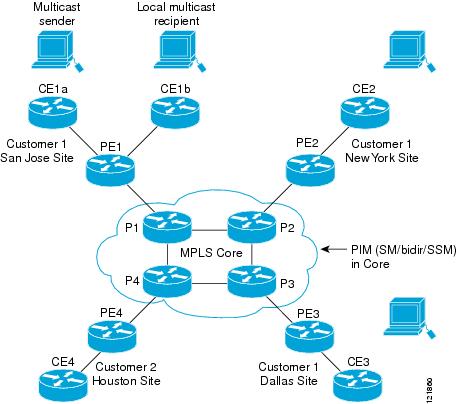
In the following example, a service provider has a multicast customer with offices in San Jose, New York, and Dallas. A one-way multicast presentation is occurring in San Jose. The service provider network supports all three sites associated with this customer, in addition to the Houston site of a different enterprise customer.
The default MDT for the enterprise customer consists of provider routers P1, P2, and P3 and their associated PE routers. PE4 is not part of the default MDT, because it is associated with a different customer. The figure shows that no data flows along the default MDT, because no one outside of San Jose has joined the multicast.
An employee in New York joins the multicast session. The PE router associated with the New York site sends a join request that flows across the default MDT for the multicast domain of the customer. PE1, the PE router associated with the multicast session source, receives the request. The figure depicts that the PE router forwards the request to the CE router associated with the multicast source (CE1a).
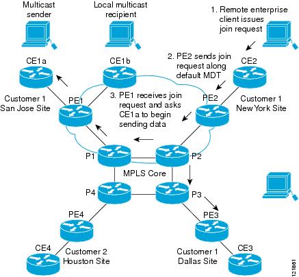
The CE router (CE1a) begins to send the multicast data to the associated PE router (PE1), which sends the multicast data along the default MDT. Immediately sending the multicast data, PE1 recognizes that the multicast data exceeds the bandwidth threshold for which a data MDT should be created. Therefore, PE1 creates a data MDT, sends a message to all routers using the default MDT that contains information about the data MDT, and, three seconds later, begins sending the multicast data for that particular stream using the data MDT. Only PE2 has interested receivers for this source, so only PE2 will join the data MDT and receive traffic on it.
PE routers maintain a PIM relationship with other PE routers over the default MDT and a PIM relationship with its directly attached PE routers.
Multicast Tunnel Interface
An MVRF, which is created per multicast domain, requires the router to create a tunnel interface from which all MVRF traffic is sourced. A multicast tunnel interface is an interface the MVRF uses to access the multicast domain. It can be thought of as a conduit that connects an MVRF and the global MVRF. One tunnel interface is created per MVRF.
Multicast Distributed Switching Support for Multicast VPN
Multicast distributed switching (MDS) is supported for MVPN on the Cisco 7500 series routers. When MDS is configured, ensure that all interfaces enabled for IP multicast have MDS enabled correctly--verify that no interface has the no ip mroute-cache command configured (including loopback interfaces).
MDT Address Family in BGP for Multicast VPN
The mdt keyword has been added to the address-family ipv4 command to configure an MDT address-family session. MDT address-family sessions are used to pass the source PE address and MDT group address to PIM using Border Gateway Protocol (BGP) MDT Subaddress Family Identifier (SAFI) updates.
- BGP Advertisement Methods for Multicast VPN Support
- Automigration to the MDT SAFI
- Guidelines for Configuring the MDT SAFI
- Guidelines for Upgrading a Network to Support the MDT SAFI
- Supported Policy
BGP Advertisement Methods for Multicast VPN Support
In a single autonomous system, if the default MDT for an MVPN is using PIM sparse mode (PIM-SM) with a rendezvous point (RP), then PIM is able to establish adjacencies over the Multicast Tunnel Interface (MTI) because the source PE and receiver PE discover each other through the RP. In this scenario, the local PE (the source PE) sends register messages to the RP, which then builds a shortest-path tree (SPT) toward the source PE. The remote PE, which acts as a receiver for the MDT multicast group, then sends (*, G) joins toward the RP and joins the distribution tree for that group.
However, if the default MDT group is configured in a PIM Source Specific Multicast (PIM-SSM) environment rather than a PIM-SM environment, the receiver PE needs information about the source PE and the default MDT group. This information is used to send (S, G) joins toward the source PE to build a distribution tree from the source PE (without the need for an RP). The source PE address and default MDT group address are sent using BGP.
The table lists the BGP advertisement methods for sending the source PE address and the default MDT group that are available (by Cisco IOS release).
BGP Extended Community
When BGP extended communities are used, the PE loopback (source address) information is sent as a VPNv4 prefix using Route Distinguisher (RD) Type 2 (to distinguish it from unicast VPNv4 prefixes). The MDT group address is carried in a BGP extended community. Using a combination of the embedded source in the VPNv4 address and the group in the extended community, PE routers in the same MVRF instance can establish SSM trees to each other.
BGP MDT SAFI
In Cisco IOS releases that support the MDT SAFI, the source PE address and the MDT group address are passed to PIM using BGP MDT SAFI updates. The RD type has changed to RD type 0 and BGP determines the best path for the MDT updates before passing the information to PIM.
 Note | To prevent backwards-compatibility issues, BGP allows the communication of the older style updates with peers that are unable to understand the MDT SAFI address family. |
In Cisco IOS releases that support the MDT SAFI, the MDT SAFI address family needs to be explicitly configured for BGP neighbors using the address-family ipv4 mdt command. Neighbors that do not support the MDT SAFI still need to be enabled for the MDT SAFI in the local BGP configuration. Prior to the introduction of the MDT SAFI, additional BGP configuration from the VPNv4 unicast configuration was not needed to support MVPN.
Because the new MDT SAFI does not use BGP route-target extended communities, the regular extended community methods to filter these updates no longer apply. As a result, the match mdt-group route-map configuration command has been added to filter on the MDT group address using Access Control Lists (ACLs). These route maps can be applied--inbound or outbound--to the IPv4 MDT address-family neighbor configuration.
Automigration to the MDT SAFI
In Cisco IOS Release 12.0(30)S3, automigration to the MDT SAFI functionality was introduced to ease the migration to the MDT SAFI. This functionality was integrated into Cisco IOS Releases 12.2(33)SRA1, 12.2(31)SB2, and 12.2(33)SXH. When migrating a Cisco IOS release to the MDT SAFI, existing VPNv4 neighbors will be automatically configured for the MDT SAFI upon bootup based on the presence of an existing default MDT configuration (that is, pre-MDT SAFI configurations will be automatically converted to an MDT SAFI configuration upon bootup). In addition, when a default MDT configuration exists and a VPNv4 neighbor in BGP is configured, a similar neighbor in the IPv4 MDT address family will be automatically configured.
Guidelines for Configuring the MDT SAFI
- We recommend that you configure the MDT SAFI on all routers that participate in the MVPN. Even though the benefits of the MDT SAFI are for SSM tree building, the MDT SAFI must also be configured when using MVPN with the default MDT group for PIM-SM. From the multicast point of view, the MDT SAFI is not required for MVPN to work within a PIM-SM core. However, in certain scenarios, the new address family must be configured in order to create the MTI. Without this notification, the MTI would not be created and MVPN would not function (even with PIM-SM).
- For backward compatible sessions, extended communities must be enabled on all MDT SAFI peers. In a pure MDT SAFI environment there is no need to configure extended communities explicitly for MVPN. However, extended communities will be needed for VPNv4 interior BGP (iBGP) sessions to relay the route-target. In a hybrid (MDT SAFI and pre-MDT SAFI) environment, extended communities must be configured to send the embedded source in the VPNv4 address and the MDT group address to MDT SAFI neighbors.
Guidelines for Upgrading a Network to Support the MDT SAFI
When moving from a pre-MDT SAFI to an MDT SAFI environment, the upmost care should be taken to minimize the impact to the MVPN service. The unicast service will not be affected, other than the outage due to the reload and recovery. To upgrade a network to support the MDT SAFI, we recommend that you perform the following steps:
- Upgrade the PEs in the MVPN to a Cisco IOS release that supports the MDT SAFI. Upon bootup, the PE configurations will be automigrated to the MDT SAFI. For more information about the automigration to the MDT SAFI functionality, see the Automigration to the MDT SAFI section.
- After the PEs have been upgraded, upgrade the RRs and enable the MDT SAFI for all peers providing MVPN service. Enabling or disabling the MDT SAFI will reset the BGP peer relationship for all address families; thus, a loss of routing information may occur.
How to Configure Multicast VPN
- Configuring a Default MDT Group for a VRF
- Configuring the MDT Address Family in BGP for Multicast VPN
- Configuring the Data Multicast Group
- Configuring Multicast Routes and Information
- Verifying Information for the MDT Default Group
Configuring a Default MDT Group for a VRF
Perform this task to configure a default MDT group for a VRF.
The default MDT group must be the same group configured on all routers that belong to the same VPN. The source IP address will be the address used to source the BGP sessions.
DETAILED STEPS
Configuring the MDT Address Family in BGP for Multicast VPN
Perform this task to configure an MDT address family session on PE routers to establish MDT peering sessions for MVPN.
Before MVPN peering can be established through an MDT address family, MPLS and Cisco Express Forwarding (CEF) must be configured in the BGP network and multiprotocol BGP on PE routers that provide VPN services to CE routers.
DETAILED STEPS
Configuring the Data Multicast Group
Perform this task to configure a data MDT group.
A data MDT group can include a maximum of 256 multicast groups per VPN per VRF per PE router. Multicast groups used to create the data MDT group are dynamically chosen from a pool of configured IP addresses.
- Before configuring a default MDT group, the VPN must be configured for multicast routing as described in the Configuring a Default MDT Group for a VRF.
- All access lists needed when using the tasks in this module should be configured prior to beginning the configuration task. For information about how to configure an access list, see the " Creating an IP Access List and Applying It to an Interface " module.
DETAILED STEPS
Configuring Multicast Routes and Information
- Before configuring a default MDT group, the VPN must be configured for multicast routing as described in the Configuring a Default MDT Group for a VRF.
- All access lists needed when using the tasks in this module should be configured prior to beginning the configuration task. For information about how to configure an access list, see the " Creating an IP Access List and Applying It to an Interface " module.
DETAILED STEPS
Verifying Information for the MDT Default Group
DETAILED STEPS
Configuration Examples for Multicast VPN
- Configuring MVPN and SSM Example
- Enabling a VPN for Multicast Routing Example
- Configuring the MDT Address Family in BGP for Multicast VPN Example
- Configuring the Multicast Group Address Range for Data MDT Groups Example
- Limiting the Number of Multicast Routes Example
Configuring MVPN and SSM Example
In the following example, PIM-SSM is configured in the backbone. Therefore, the default and data MDT groups are configured within the SSM range of IP addresses. Inside the VPN, PIM-SM is configured and only Auto-RP announcements are accepted.
ip vrf vrf1
 rd 1:1
 route-target export 1:1
 route-target import 1:1
 mdt default 232.0.0.1
 mdt data 232.0.1.0 0.0.0.255 threshold 500 list 101
!
ip pim ssm default
ip pim vrf vrf1 accept-rp auto-rp
Configuring the MDT Address Family in BGP for Multicast VPN Example
In the following example, an MDT address family session is configured on a PE router to establish MDT peering sessions for MVPN.
!
ip vrf test
 rd 55:2222
 route-target export 55:2222
 route-target import 55:2222
 mdt default 232.0.0.1
!
ip multicast-routing
ip multicast-routing vrf test
!
router bgp 55
.
.
.
!
 address-family vpnv4
 neighbor 192.168.1.1 activate
 neighbor 192.168.1.1 send-community both
!
 address-family ipv4 mdt
 neighbor 192.168.1.1 activate
 neighbor 192.168.1.1 send-community both
!
Configuring the Multicast Group Address Range for Data MDT Groups Example
In the following example, the VPN routing instance is assigned a VRF named blue. The MDT default group for a VPN VRF is 239.1.1.1, and the multicast group address range for MDT groups is 239.1.2.0 with wildcard bits of 0.0.0.3:
ip vrf blue
 rd 55:1111
 route-target both 55:1111
 mdt default 239.1.1.1
 mdt data 239.1.2.0 0.0.0.3
 end
Limiting the Number of Multicast Routes Example
In the following example, the number of multicast routes that can be added in to a multicast routing table is set to 200,000 and the threshold value of the number of mroutes that will cause a warning message to occur is set to 20,000:
!
ip multicast-routing distributed
ip multicast-routing vrf cisco distributed
ip multicast cache-headers
ip multicast route-limit 200000 20000
ip multicast vrf cisco route-limit 200000 20000
no mpls traffic-eng auto-bw timers frequency 0
!
Additional References
Related Documents
|
Related Topic |
Document Title |
|---|---|
|
Extranet MVPN concepts, tasks, and configuration examples |
" Configuring Multicast VPN Extranet Support " module |
|
Inter-AS MVPN concepts, tasks, and configuration examples |
" Configuring Multicast VPN Inter-AS Support " module |
|
MVPN MIB concepts and tasks |
" Multicast VPN MIB " module |
|
IP multicast commands: complete command syntax, command mode, command history, defaults, usage guidelines, and examples |
Cisco IOS IP Multicast Command Reference |
MIBs
Technical Assistance
|
Description |
Link |
|---|---|
|
The Cisco Support website provides extensive online resources, including documentation and tools for troubleshooting and resolving technical issues with Cisco products and technologies. To receive security and technical information about your products, you can subscribe to various services, such as the Product Alert Tool (accessed from Field Notices), the Cisco Technical Services Newsletter, and Really Simple Syndication (RSS) Feeds. Access to most tools on the Cisco Support website requires a Cisco.com user ID and password. |
Feature Information for Configuring Multicast VPN
The following table provides release information about the feature or features described in this module. This table lists only the software release that introduced support for a given feature in a given software release train. Unless noted otherwise, subsequent releases of that software release train also support that feature.
Use Cisco Feature Navigator to find information about platform support and Cisco software image support. To access Cisco Feature Navigator, go to www.cisco.com/go/cfn. An account on Cisco.com is not required.
| Table 2 | Feature Information for Configuring Multicast VPN |
|
Feature Name |
Releases |
Feature Information |
|---|---|---|
|
Multicast VPN--IP Multicast Support of MPLS VPNs |
12.0(23)S 12.2(13)T 12.2(14)S 12.0(25)S1 12.0(26)S 12.0(32)SY 12.2(18)SXE 15.0(1)S |
The Multicast VPN feature provides the ability to support multicast over a Layer 3 Virtual Private Network (VPN). As enterprises extend the reach of their multicast applications, service providers can accommodate these enterprises over their Multiprotocol Label Switching (MPLS) core network. IP multicast is used to stream video, voice, and data to an MPLS VPN network core. In Cisco IOS Release 12.2(18)SXE, support for this feature on the Cisco Catalyst 6000 Series Switches was added. |
Cisco and the Cisco Logo are trademarks of Cisco Systems, Inc. and/or its affiliates in the U.S. and other countries. A listing of Cisco's trademarks can be found at www.cisco.com/go/trademarks. Third party trademarks mentioned are the property of their respective owners. The use of the word partner does not imply a partnership relationship between Cisco and any other company. (1005R)
Any Internet Protocol (IP) addresses and phone numbers used in this document are not intended to be actual addresses and phone numbers. Any examples, command display output, network topology diagrams, and other figures included in the document are shown for illustrative purposes only. Any use of actual IP addresses or phone numbers in illustrative content is unintentional and coincidental.