
 Feedback
Contents
- Configuring Router-Port Group Management Protocol
- Finding Feature Information
- Prerequisites for RGMP
- Information About RGMP
- IP Multicast Routing Overview
- RGMP Overview
- How to Configure RGMP
- Enabling RGMP
- Verifying RGMP Configuration
- Monitoring and Maintaining RGMP
- Configuration Examples for RGMP
- RGMP Configuration Example
- Additional References
Configuring Router-Port Group Management Protocol
Router-Port Group Management Protocol (RGMP) is a Cisco protocol that restricts IP multicast traffic in switched networks. RGMP is a Layer 2 protocol that enables a router to communicate to a switch (or a networking device that is functioning as a Layer 2 switch) the multicast group for which the router would like to receive or forward traffic. RGMP restricts multicast traffic at the ports of RGMP-enabled switches that lead to interfaces of RGMP-enabled routers.
Finding Feature Information
Your software release may not support all the features documented in this module. For the latest feature information and caveats, see the release notes for your platform and software release. To find information about the features documented in this module, and to see a list of the releases in which each feature is supported, see the Feature Information Table at the end of this document.
Use Cisco Feature Navigator to find information about platform support and Cisco software image support. To access Cisco Feature Navigator, go to www.cisco.com/go/cfn. An account on Cisco.com is not required.
Prerequisites for RGMP
Before you enable RGMP, ensure that the following features are enabled on your router:
- IP routing
- IP multicast
- PIM in sparse mode, sparse-dense mode, source specific mode, or bidirectional mode
If your router is in a bidirectional group, make sure to enable RGMP only on interfaces that do not function as a designated forwarder (DF). If you enable RGMP on an interface that functions as a DF, the interface will not forward multicast packets up the bidirectional shared tree to the rendezvous point (RP).
You must have the following features enabled on your switch:
- IP multicast
- IGMP snooping
 Note | Refer to the Catalyst switch software documentation for RGMP switch configuration tasks and command information. |
Information About RGMP
IP Multicast Routing Overview
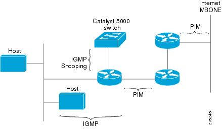
The software supports the following protocols to implement IP multicast routing:
- Internet Group Management Protocol (IGMP) is used between hosts on a LAN and the routers on that LAN to track the multicast groups of which hosts are members.
- Protocol Independent Multicast (PIM) is used between routers so that they can track which multicast packets to forward to each other and to their directly connected LANs.
- Cisco Group Management Protocol (CGMP) is a protocol used on routers connected to Catalyst switches to perform tasks similar to those performed by IGMP.
- RGMP is a protocol used on routers connected to Catalyst switches or networking devices functioning as Layer 2 switches to restrict IP multicast traffic. Specifically, the protocol enables a router to communicate to a switch the IP multicast group for which the router would like to receive or forward traffic.
The figure shows where these protocols operate within the IP multicast environment.
RGMP Overview
RGMP enables a router to communicate to a switch the IP multicast group for which the router would like to receive or forward traffic. RGMP is designed for switched Ethernet backbone networks running PIM sparse mode (PIM-SM) or sparse-dense mode.
The figure shows a switched Ethernet backbone network running PIM in sparse mode, RGMP, and IGMP snooping.
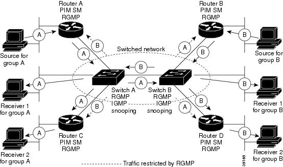
In the figure, the sources for the two different multicast groups (the source for group A and the source for group B) send traffic into the same switched network. Without RGMP, traffic from source A is unnecessarily flooded from switch A to switch B, then to router B and router D. Also, traffic from source B is unnecessarily flooded from switch B to switch A, then to router A and router C. With RGMP enabled on all routers and switches in this network, traffic from source A would not flood router B and router D. Also, traffic from source B would not flood router A and router C. Traffic from both sources would still flood the link between switch A and switch B. Flooding over this link would still occur because RGMP does not restrict traffic on links toward other RGMP-enabled switches with routers behind them.
By restricting unwanted multicast traffic in a switched network, RGMP increases the available bandwidth for all other multicast traffic in the network and saves the processing resources of the routers.
The figure shows the RGMP messages sent between an RGMP-enabled router and an RGMP-enabled switch.

The router sends simultaneous PIM hello (or a PIM query message if PIM Version 1 is configured) and RGMP hello messages to the switch. The PIM hello message is used to locate neighboring PIM routers. The RGMP hello message instructs the switch to restrict all multicast traffic on the interface from which the switch received the RGMP hello message.
The router sends the switch an RGMP join <G> message (where G is the multicast group address) when the router wants to receive traffic for a specific multicast group. The RGMP join message instructs the switch to forward multicast traffic for group <G> out the interface from which the switch received the RGMP hello message.
The router sends the switch an RGMP leave <G> message when the router wants to stop receiving traffic for a specific multicast group. The RGMP leave message instructs the switch to stop forwarding the multicast traffic on the port from which the switch received the PIM and RGMP hello messages.
The router sends the switch an RGMP bye message when RGMP is disabled on the router. The RGMP bye message instructs the switch to forward the router all IP multicast traffic on the port from which the switch received the PIM and RGMP hello messages, as long as the switch continues to receive PIM hello messages on the port.
How to Configure RGMP
Enabling RGMP
To enable RGMP, use the following commands on all routers in your network beginning in global configuration mode:
DETAILED STEPS
See the "RGMP_Configuration_Example" section for an example of how to configure RGMP.
Verifying RGMP Configuration
To verify that RGMP is enabled on the correct interfaces, use the show ip igmp interfacecommand:
Router> show ip igmp interface
gigabitethernet1/0 is up, line protocol is up
  Internet address is 10.0.0.0/24
    IGMP is enabled on interface
  Current IGMP version is 2
    RGMP is enabled
  IGMP query interval is 60 seconds
  IGMP querier timeout is 120 seconds
  IGMP max query response time is 10 seconds
  Last member query response interval is 1000 ms
  Inbound IGMP access group is not set
  IGMP activity: 1 joins, 0 leaves
  Multicast routing is enabled on interface
  Multicast TTL threshold is 0
  Multicast designated router (DR) is 10.0.0.0 (this system)
  IGMP querying router is 10.0.0.0 (this system)
  Multicast groups joined (number of users):
      224.0.1.40(1)
Note | If RGMP is not enabled on an interface, no RGMP information is displayed in the show ip igmp interface command output for that interface. |
Monitoring and Maintaining RGMP
To enable RGMP debugging, use the following command in privileged EXEC mode:
|
Command |
Purpose |
|---|---|
Router# debug ip rgmp
|
Logs debug messages sent by an RGMP-enabled router. Using the command without arguments logs RGMP Join <G> and RGMP leave <G> messages for all multicast groups configured on the router. Using the command with arguments logs RGMP join <G> and RGMP leave <G> messages for the specified group. |
The figure shows the debug messages that are logged by an RGMP-enabled router as the router sends RGMP join <G> and RGMP leave <G> messages to an RGMP-enabled switch.

Configuration Examples for RGMP
RGMP Configuration Example
This section provides an RGMP configuration example that shows the individual configurations for the routers and switches shown in the figure.
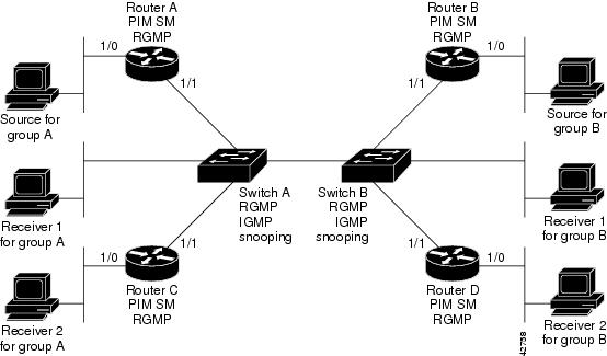
Router A Configuration
   ip routing
   ip multicast-routing distributed
   interface gigabitethernet 1/0/0
     ip address 10.0.0.1 255.0.0.0
     ip pim sparse-dense-mode
     no shutdown
   interface gigabitethernet 1/1/0
     ip address 10.1.0.1 255.0.0.0
     ip pim sparse-dense-mode
     ip rgmp
     no shutdown
Router B Configuration
   ip routing
   ip multicast-routing distributed
   interface gigabitethernet 1/0/0
     ip address 10.2.0.1 255.0.0.0
     ip pim sparse-dense-mode
     no shutdown
   interface gigabitethernet 1/1/0
     ip address 10.3.0.1 255.0.0.0
     ip pim sparse-dense-mode
     ip rgmp
     no shutdown
Router C Configuration
   ip routing
   ip multicast-routing distributed
   interface gigabitethernet 1/0/0
     ip address 10.4.0.1 255.0.0.0
     ip pim sparse-dense-mode
     no shutdown
   interface gigabitethernet 1/1/0
     ip address 10.5.0.1 255.0.0.0
     ip pim sparse-dense-mode
     ip rgmp
     no shutdown
Additional References
MIBs
Technical Assistance
|
Description |
Link |
|---|---|
|
The Cisco Support website provides extensive online resources, including documentation and tools for troubleshooting and resolving technical issues with Cisco products and technologies. To receive security and technical information about your products, you can subscribe to various services, such as the Product Alert Tool (accessed from Field Notices), the Cisco Technical Services Newsletter, and Really Simple Syndication (RSS) Feeds. Access to most tools on the Cisco Support website requires a Cisco.com user ID and password. |
Cisco and the Cisco Logo are trademarks of Cisco Systems, Inc. and/or its affiliates in the U.S. and other countries. A listing of Cisco's trademarks can be found at www.cisco.com/go/trademarks. Third party trademarks mentioned are the property of their respective owners. The use of the word partner does not imply a partnership relationship between Cisco and any other company. (1005R)
Any Internet Protocol (IP) addresses and phone numbers used in this document are not intended to be actual addresses and phone numbers. Any examples, command display output, network topology diagrams, and other figures included in the document are shown for illustrative purposes only. Any use of actual IP addresses or phone numbers in illustrative content is unintentional and coincidental.