
 Feedback
Contents
- Configuring NAT for IP Address Conservation
- Finding Feature Information
- Prerequisites for Configuring NAT for IP Address Conservation
- Access Lists
- NAT Requirements
- Restrictions for Configuring NAT for IP Address Conservation
- Information About Configuring NAT for IP Address Conservation
- Benefits of Configuring NAT for IP Address Conservation
- Purpose of NAT
- How NAT Works
- Types of NAT
- Uses of NAT
- NAT Inside and Outside Addresses
- Inside Source Address Translation
- Overloading of Inside Global Addresses
- Address Translation of Overlapping Networks
- NAT Virtual Interface
- TCP Load Distribution for NAT
- Static IP Address Support
- Route Map Overview
- RADIUS
- Rate Limiting NAT Translation Feature
- Viruses and Worms That Target NAT
- Denial-of-Service Attacks
- Reenabling RTSP on a NAT Router
- How to Configure NAT for IP Address Conservation
- Configuring Inside Source Addresses
- Configuring Static Translation of Inside Source Addresses
- Configuring Dynamic Translation of Inside Source Addresses
- Allowing Overlapping Networks to Communicate Using NAT
- Configuring Static Translation of Overlapping Networks
- Configuring Dynamic Translation of Overlapping Networks
- Using NAT to Allow Internal Users Access to the Internet
- Configuring NAT of External IP Addresses Only
- Configuring the NAT Default Inside Server Feature
- Configuring the NAT Virtual Interface
- Enabling a Static NAT Virtual Interface
- Enabling a Dynamic NAT Virtual Interface
- Configuring Server TCP Load Balancing
- Configuring Support for Users with Static IP Addresses
- Enabling Route Maps on Inside Interfaces
- Enabling NAT Route Maps Outside-to-Inside Support
- Configuring the Rate Limiting NAT Translation Feature
- Configuring Support for ARP Ping
- Configuring Address Translation Timeouts
- Changing the Default Timeouts for Protocol-Based Translations
- Configuration Examples for Configuring NAT for IP Address Conservation
- Example: Configuring Inside Source Addresses
- Example: Configuring Static Translation of Inside Source Addresses
- Example: Configuring Dynamic Translation of Inside Source Addresses
- Example: Allowing Overlapping Networks to Communicate Using NAT
- Example: Using NAT to Allow Internal Users Access to the Internet
- Example: Configuring NAT of External IP Addresses Only
- Example: Configuring the NAT Inside Server Feature
- Example: Configuring the NAT Virtual Interface
- Example: Configuring Server TCP Load Balancing
- Example: Configuring Support for Users with Static IP Addresses
- Example: Enabling Route Maps on Inside Interfaces
- Example: Enabling NAT Route Maps Outside-to-Inside Support
- Example: Configuring the Rate Limiting NAT Translation Feature
- Example: Configuring Support for ARP Ping
- Where to Go Next
- Additional References
- Feature Information for Configuring NAT for IP Address Conservation
Configuring NAT for IP Address Conservation
This module describes how to configure Network Address Translation (NAT) for IP address conservation and configure inside and outside source addresses. This module also provides information about the benefits of configuring NAT for IP address conservation.
NAT enables private IP internetworks that use nonregistered IP addresses to connect to the Internet. NAT operates on a router, usually connecting two networks, and translates the private (not globally unique) addresses in the internal network into legal addresses before packets are forwarded onto another network. NAT can be configured to advertise only one address for the entire network to the outside world. This ability provides additional security by effectively hiding the entire internal network behind that one address.
NAT is also used at the enterprise edge to allow internal users access to the Internet and to allow Internet access to internal devices such as mail servers.
- Finding Feature Information
- Prerequisites for Configuring NAT for IP Address Conservation
- Restrictions for Configuring NAT for IP Address Conservation
- Information About Configuring NAT for IP Address Conservation
- How to Configure NAT for IP Address Conservation
- Configuration Examples for Configuring NAT for IP Address Conservation
- Where to Go Next
- Additional References
- Feature Information for Configuring NAT for IP Address Conservation
Finding Feature Information
Your software release may not support all the features documented in this module. For the latest feature information and caveats, see the release notes for your platform and software release. To find information about the features documented in this module, and to see a list of the releases in which each feature is supported, see the Feature Information Table at the end of this document.
Use Cisco Feature Navigator to find information about platform support and Cisco software image support. To access Cisco Feature Navigator, go to www.cisco.com/go/cfn. An account on Cisco.com is not required.
Prerequisites for Configuring NAT for IP Address Conservation
Access Lists
All access lists required for use with the configuration tasks described in this module should be configured prior to beginning a configuration task. For information about how to configure an access list, refer to the IP Access List Sequence Numbering document.
 Note | If you specify an access list with a NAT command, NAT will not support the permit ip any any command that is commonly used in an access list. |
NAT Requirements
Before configuring NAT in your network, you should know interfaces on which NAT will be configured and for what purposes. The following requirements will help you decide how to configure and use NAT:
- Define the NAT inside and outside interfaces if:
- Define what you need NAT to accomplish:
- Allow internal users to access the Internet.
- Allow the Internet to access internal devices such as a mail server.
- Allow overlapping networks to communicate.
- Allow networks with different address schemes to communicate.
- Allow the use of an application level gateway.
- Redirect TCP traffic to another TCP port or address.
- Use NAT during a network transition.
Restrictions for Configuring NAT for IP Address Conservation
- It is not practical to use NAT if a large number of hosts in the stub domain communicate outside of the domain.
- Some applications use embedded IP addresses in such a way that translation by a NAT device is impractical. These applications either may not work transparently or not work at all through a NAT device.
- NAT hides the identity of hosts, which may be an advantage or a disadvantage, depending on the desired result.
- A router configured with NAT must not advertise the local networks to the outside. However, routing information that NAT receives from the outside can be advertised in the stub domain as usual.
- If you specify an access list with a NAT command, NAT will not support the permit ip any any command commonly used in the access list.
- NAT configuration is not supported on the access side of the Intelligent Services Gateway (ISG).
Information About Configuring NAT for IP Address Conservation
- Benefits of Configuring NAT for IP Address Conservation
- Purpose of NAT
- How NAT Works
- Types of NAT
- Uses of NAT
- NAT Inside and Outside Addresses
- Address Translation of Overlapping Networks
- NAT Virtual Interface
- TCP Load Distribution for NAT
- Static IP Address Support
- Route Map Overview
- RADIUS
- Rate Limiting NAT Translation Feature
- Viruses and Worms That Target NAT
- Denial-of-Service Attacks
- Reenabling RTSP on a NAT Router
Benefits of Configuring NAT for IP Address Conservation
NAT allows organizations to resolve the problem of IP address depletion when they have existing networks and need to access the Internet. Sites that do not yet possess Network Information Center (NIC)-registered IP addresses must acquire IP addresses, and if more than 254 clients are present or are planned, the scarcity of Class B addresses becomes a serious issue. NAT addresses these issues by mapping thousands of hidden internal addresses to a range of easy-to-get Class C addresses.
Sites that already have registered IP addresses for clients on an internal network may want to hide those addresses from the Internet so that hackers cannot directly attack clients. With client addresses hidden, a degree of security is established. NAT gives LAN administrators complete freedom to expand Class A addressing, which is drawn from the reserve pool of the Internet Assigned Numbers Authority (RFC 1597). The expansion of Class A addresses occurs within the organization without a concern for addressing changes at the LAN or the Internet interface.
Cisco software can selectively or dynamically perform NAT. This flexibility allows network administrator to use a mix of RFC 1597 and RFC 1918 addresses or registered addresses.
NAT is designed for use on a variety of routers for IP address simplification and conservation. In addition, NAT allows the selection of internal hosts that are available for NAT.
A significant advantage of NAT is that it can be configured without requiring any changes to hosts or routers other than to those few routers on which NAT will be configured.
Purpose of NAT
NAT is a feature that allows the IP network of an organization to appear from the outside to use a different IP address space than what it is actually using. Thus, NAT allows an organization with nonglobally routable addresses to connect to the Internet by translating those addresses into a globally routable address space. NAT also allows a graceful renumbering strategy for organizations that are changing service providers or voluntarily renumbering into classless interdomain routing (CIDR) blocks. NAT is described in RFC 1631.
Beginning with Cisco IOS Release 12.1(5)T, NAT supports all H.225 and H.245 message types, including FastConnect and Alerting, as part of the H.323 Version 2 specification. Any product that makes use of these message types will be able to pass through a Cisco NAT configuration without any static configuration. Full support for NetMeeting Directory (Internet Locator Service) is also provided through NAT.
How NAT Works
A router configured with NAT will have at least one interface to the inside network and one to the outside network. In a typical environment, NAT is configured at the exit router between a stub domain and the backbone. When a packet leaves the domain, NAT translates the locally significant source address into a globally unique address. When a packet enters the domain, NAT translates the globally unique destination address into a local address. If more than one exit point exists, each NAT must have the same translation table. If NAT cannot allocate an address because it has run out of addresses, it drops the packet and sends an Internet Control Message Protocol (ICMP) host unreachable packet to the destination.
Types of NAT
NAT operates on a router--generally connecting only two networks--and translates the private (inside local) addresses within the internal network into public (inside global) addresses before any packets are forwarded to another network. This functionality gives you the option to configure NAT so that it will advertise only a single address for your entire network to the outside world. Doing this effectively hides the internal network from the world, giving you some additional security.
The types of NAT include:
- Static address translation (static NAT)--Allows one-to-one mapping between local and global addresses.
- Dynamic address translation (dynamic NAT)--Maps unregistered IP addresses to registered IP addresses from a pool of registered IP addresses.
- Overloading--Maps multiple unregistered IP addresses to a single registered IP address (many to one) using different ports. This method is also known as Port Address Translation (PAT). By using overloading, thousands of users can be connected to the Internet by using only one real global IP address.
Uses of NAT
NAT can be used for the following applications:
- When you want to connect to the Internet, but not all of your hosts have globally unique IP addresses. NAT enables private IP internetworks that use nonregistered IP addresses to connect to the Internet. NAT is configured on the router at the border of a stub domain (referred to as the inside network) and a public network such as the Internet (referred to as the outside network). NAT translates internal local addresses to globally unique IP addresses before sending packets to the outside network. As a solution to the connectivity problem, NAT is practical only when relatively few hosts in a stub domain communicate outside of the domain at the same time. When this is the case, only a small subset of the IP addresses in the domain must be translated into globally unique IP addresses when outside communication is necessary, and these addresses can be reused when they are no longer in use.
- When you must change your internal addresses. Instead of changing the internal addresses, which can be a considerable amount of work, you can translate them by using NAT.
- When you want to do basic load sharing of TCP traffic. You can map a single global IP address to many local IP addresses by using the TCP load distribution feature.
NAT Inside and Outside Addresses
The term inside in a NAT context refers to networks owned by an organization that must be translated. When NAT is configured, hosts within this network will have addresses in one space (known as the local address space) that will appear to those outside the network as being in another space (known as the global address space).
Similarly, the term outside refers to those networks to which the stub network connects, and which are generally not under the control of an organization. Hosts in outside networks can also be subject to translation, and can thus have local and global addresses.
NAT uses the following definitions:
- Inside local address--The IP address that is assigned to a host on the inside network. The address is probably not a legitimate IP address assigned by the NIC or service provider.
- Inside global address--A legitimate IP address (assigned by the NIC or service provider) that represents one or more inside local IP addresses to the outside world.
- Outside local address--The IP address of an outside host as it appears to the inside network. Not necessarily a legitimate address, it is allocated from the address space routable on the inside.
- Outside global address--The IP address assigned to a host on the outside network by the owner of the host. The address is allocated from a globally routable address or network space.
This section describes the following topics:
Inside Source Address Translation
You can translate your own IP addresses into globally unique IP addresses when communicating outside of your network. You can configure static or dynamic inside source translation as follows:
- Static translation establishes a one-to-one mapping between your inside local address and an inside global address. Static translation is useful when a host on the inside must be accessible by a fixed address from the outside.
- Dynamic translation establishes a mapping between an inside local address and a pool of global addresses.
In Cisco IOS Release 15.1(3)T and later releases, when you configure the traceroute command, NAT returns the same inside global IP address for all inside local IP addresses.
The figure below illustrates a router that is translating a source address inside a network to a source address outside the network.
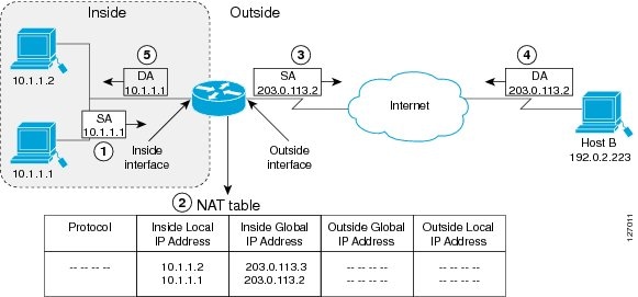
The following process describes the inside source address translation, as shown in the figure above:
- The user at host 10.1.1.1 opens a connection to Host B in the outside network.
- The first packet that the router receives from host 10.1.1.1 causes the router to check its NAT table and based on your NAT configuration, the following scenarios are possible:
- If a static translation entry is configured, the router goes to Step 3.
- If no translation entry exists, the router determines that the source address (SA) 10.1.1.1 must be translated dynamically, selects a legal, global address from the dynamic address pool, and creates a translation entry in the NAT table. This type of translation entry is called a simple entry.
- The router replaces the inside local source address of host 10.1.1.1 with the global address of the translation entry and forwards the packet.
- Host B receives the packet and responds to host 10.1.1.1 by using the inside global IP destination address (DA) 203.0.113.2.
- When the router receives the packet with the inside global IP address, it performs a NAT table lookup by using the inside global address as a key. It then translates the address to the inside local address of host 10.1.1.1 and forwards the packet to host 10.1.1.1.
Host 10.1.1.1 receives the packet and continues the conversation. The router performs Steps 2 to 5 for each packet that it receives.
Overloading of Inside Global Addresses
You can conserve addresses in the inside global address pool by allowing a router to use one global address for many local addresses and this type of NAT configuration is called overloading. When overloading is configured, the router maintains enough information from higher-level protocols (for example, TCP or UDP port numbers) to translate the global address back to the correct local address. When multiple local addresses map to one global address, the TCP or UDP port numbers of each inside host distinguish between local addresses.
The figure below illustrates a NAT operation when a inside global address represents multiple inside local addresses. The TCP port numbers act as differentiators.
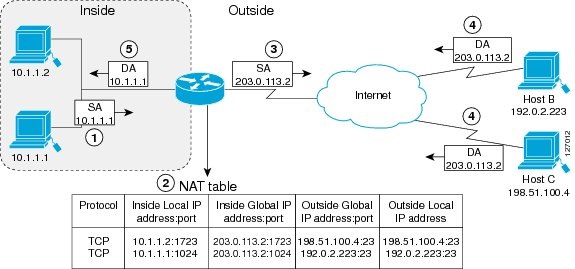
The router performs the following process in overloading inside global addresses, as shown in the figure above. Both Host B and Host C believe that they are communicating with a single host at address 203.0.113.2. They are actually communicating with different hosts; the port number is the differentiator. In fact, many inside hosts can share the inside global IP address by using many port numbers.
- The user at host 10.1.1.1 opens a connection to Host B.
- The first packet that the router receives from host 10.1.1.1 causes the router to check its NAT table and based on your NAT configuration the following scenarios are possible:
- If no translation entry exists, the router determines that the address 10.1.1.1 must be translated, and sets up a translation of the inside local address 10.1.1.1 to a legal global address.
- If overloading is enabled and another translation is active, the router reuses the global address from that translation and saves enough information that can be used to translate the global address back, as an entry in the NAT table. This type of translation entry is called an extended entry.
- The router replaces the inside local source address 10.1.1.1 with the selected global address and forwards the packet.
- Host B receives the packet and responds to host 10.1.1.1 by using the inside global IP address 203.0.113.2.
- When the router receives the packet with the inside global IP address, it performs a NAT table lookup by using the protocol, the inside global address and port, and the outside address and port as keys; translates the address to the inside local address 10.1.1.1 and forwards the packet to host 10.1.1.1.
Host 10.1.1.1 receives the packet and continues the conversation. The router performs Steps 2 to 5 for each packet it receives.
Address Translation of Overlapping Networks
NAT is used to translate your IP addresses if your IP addresses are neither legal nor officially assigned. Perhaps you can chose IP addresses that officially belong to another network. Index overlapping is when an IP address is used both illegally and legally. You can use NAT to translate inside addresses that overlap with outside addresses.
The figure below shows how NAT translates overlapping networks.
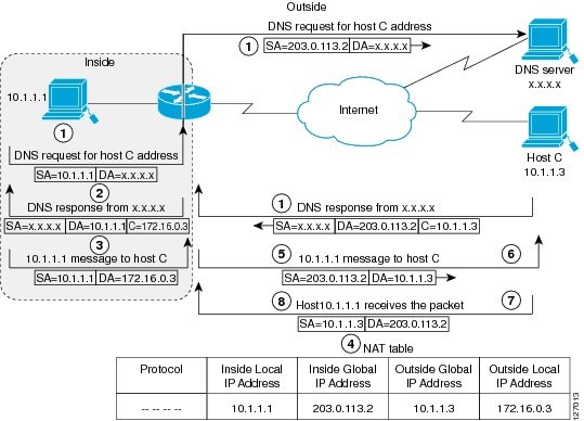
The router translates overlapping addresses as follows:
- The user at host 10.1.1.1 opens a connection to Host C by name, requesting a name-to-address lookup from a Domain Name System (DNS) server.
- The router intercepts the DNS reply and translates the returned address if there is an overlap (that is, the resulting legal address resides illegally in the inside network). To translate the return address, the router creates a simple translation entry to map the overlapping address 10.1.1.3 to an address from a separately configured, outside local address pool.
The router examines every DNS reply, to ensure that the IP address is not in the stub network. If it is, the router translates the address as follows:
- Host 10.1.1.1 opens a connection to 172.16.0.3.
- The router sets up the translation mapping of the inside local and global addresses to each other and the outside global and local addresses to each other.
- The router replaces the SA with the inside global address and replaces the DA with the outside global address.
- Host C receives the packet and continues the conversation.
- The router does a lookup, replaces the DA with the inside local address, and replaces the SA with the outside local address.
- Host 10.1.1.1 receives the packet and the conversation continues using this translation process.
NAT Virtual Interface
The NAT Virtual Interface feature allows NAT traffic flows on the virtual interface, eliminating the need to specify inside and outside domains. When a domain is specified, translation rules are applied either before or after route decisions are applied, depending on the traffic flow from inside to outside or outside to inside. Translation rules are applied to a domain only after the route decision for a NAT Virtual Interface (NVI) is applied.
When a NAT pool is shared for translating packets from multiple networks connected to a NAT router, an NVI is created and a static route is configured that forwards all packets addressed to the NAT pool to the NVI. Standard interfaces connected to various networks are configured to determine if the traffic originating from and received on the interfaces needs to be translated.
The figure below shows a typical NVI configuration.
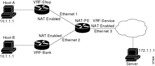
An NVI has the following benefits:
- A NAT table is maintained per interface for better performance and scalability.
- Domain-specific NAT configurations can be eliminated.
- Route maps are not supported.
-
NVI is not supported in a NAT on-a-stick scenario. The term NAT on-a-stick implies the use of a single physical interface of a router for translation. NVI is designed for traffic from one VPN routing and forwarding (VRF) instance to another and not for routing between subnets in a global routing table. For more information, see the Network Address Translation on a Stick document.
TCP Load Distribution for NAT
Your organization may have multiple hosts that must communicate with a heavily-used host. By using NAT, you can establish a virtual host on the inside network that coordinates load sharing among real hosts. DAs that match an access list are replaced with addresses from a rotary pool. Allocation is done on a round-robin basis and only when a new connection is opened from the outside to the inside. Non-TCP traffic is passed untranslated (unless other translations are in effect). The figure below illustrates this feature.

The router performs the following process when translating rotary addresses:
- The user on Host B (192.0.2.223) opens a connection to the virtual host at 10.1.1.127.
- The router receives the connection request and creates a new translation, allocating the next real host (10.1.1.1) for the inside local IP address.
- The router replaces the destination address with the selected real host address and forwards the packet.
- Host 10.1.1.1 receives the packet and responds.
- The router receives the packet and performs a NAT table lookup by using the inside local address and port number, and the outside address and port number as keys. The router then translates the source address to the address of the virtual host and forwards the packet.
- The next connection request will cause the router to allocate 10.1.1.2 for the inside local address.
Static IP Address Support
A public wireless LAN provides users of mobile computing devices with wireless connections to a public network, such as the Internet.
The NAT Static IP Address Support feature extends the capabilities of public wireless LAN providers to support users configured with a static IP address. By configuring a router to support users with a static IP address, public wireless LAN providers extend their services to a greater number of potential users, which can lead to greater user satisfaction and additional revenue.
Users with static IP addresses can use services of the public wireless LAN provider without changing their IP address. NAT entries are created for static IP clients and a routable address is provided.
Route Map Overview
For NAT, a route map must be processed instead of an access list. A route map allows you to match any combination of access lists, next-hop IP addresses, and output interfaces to determine which pool to use. The ability to use route maps with static translations enables the NAT multihoming capability with static address translations. Multihomed internal networks can host common services such as the Internet and DNS, which are accessed from different outside networks. NAT processes route map-based mappings in lexicographical order. When static NAT and dynamic NAT are configured with route maps that share the same name, static NAT is given precedence over dynamic NAT. To ensure the precedence of static NAT over dynamic NAT, you can either configure the route map associated with static NAT and dynamic NAT to share the same name or configure the static NAT route map name so that it is lexicographically lower than the dynamic NAT route map name.
Benefits of using route maps for address translation are as follows:
- The ability to configure route map statements provides the option of using IPsec with NAT.
- Translation decisions can be made based on the destination IP address when static translation entries are used.
NAT Route Maps Outside-to-Inside Support Feature
The NAT Route Maps Outside-to-Inside Support feature enables the deployment of a NAT route map configuration that allows IP sessions to be initiated from the outside to the inside.
An initial session from inside to outside is required to trigger a NAT. New translation sessions can then be initiated from the outside to the inside host that triggered the initial translation. When route maps are used to allocate global addresses, the global address can allow return traffic, and the return traffic is allowed only if it matches the defined route map in the reverse direction. The outside-to-inside functionality remains unchanged (by not creating additional entries to allow the return traffic for a route-map-based dynamic entries) unless you configure the ip nat inside source reversible command.
- Access lists with reversible route maps must be configured to match the inside-to-outside traffic.
-
In Cisco IOS Release 12.2(33)SXI5, the NAT Route Maps Outside-to-Inside Support feature is supported only on Cisco ME 6500 series Ethernet switches.
- Only IP hosts that are part of the route-map configuration will allow outside sessions.
- Outside-to-inside support is not available with PAT.
- Outside sessions must use an access list.
- The match interface and match ip next-hop commands are not supported for reversible route maps.
RADIUS
RADIUS is a distributed client/server system that secures networks against unauthorized access. Communication between a network access server (NAS) and a RADIUS server is based on UDP. Generally, the RADIUS protocol is considered a connectionless service. Issues related to server availability, retransmission, and timeouts are handled by RADIUS-enabled devices rather than the transmission protocol.
RADIUS is a client/server protocol. The RADIUS client is typically a NAS, and the RADIUS server is usually a daemon process running on a UNIX or Windows NT machine. The client passes user information to designated RADIUS servers and acts on the response that is returned. RADIUS servers receive user connection requests, authenticate the user, and then return the configuration information necessary for the client to deliver the service to the user. A RADIUS server can act as a proxy client to other RADIUS servers or other kinds of authentication servers.
Rate Limiting NAT Translation Feature
Limiting the number of concurrent NAT operations using the Rate Limiting NAT Translation feature provides users more control over how NAT addresses are used. The Rate Limiting NAT Translation feature can be used to limit the effects of viruses, worms, and DoS attacks.
Because NAT is a CPU-intensive process, router performance can be adversely affected by DoS attacks, viruses, and worms that target NAT. The Rate Limiting NAT Translation feature allows you to limit the maximum number of concurrent NAT requests on a router.
-
Classify current NAT usage and determine the sources of requests for NAT. A specific host, access control list, or VRF instance generating an unexpectedly high number of NAT requests may be the source of a malicious virus or worm attack
-
After you have identified the source of excess NAT requests, you can set a NAT rate limit that contains a specific host, access control list, or VRF instance, or you can set a general limit for the maximum number of NAT requests allowed regardless of their source.
Viruses and Worms That Target NAT
Viruses and worms are malicious programs designed to attack computer and networking equipment. Although viruses are typically embedded in discrete applications and run only when executed, worms self-propagate and can quickly spread on their own. Although a specific virus or worm may not expressly target NAT, it might use NAT resources to propagate itself. The Rate Limiting NAT Translation feature can be used to limit the impact of viruses and worms that originate from specific hosts, access control lists, and VPN routing and forwarding (VRF) instances.
Denial-of-Service Attacks
A denial-of-service (DoS) attack typically involves the misuse of standard protocols or connection processes with the intent to overload and disable a target, such as a router or web server. DoS attacks can come from a malicious user or from a computer infected with a virus or worm. An attack that comes from many different sources at once, such as when a virus or worm has infected many computers, is known as a distributed DoS attack. Such distributed DoS attacks can spread rapidly and involve thousands of systems.
Reenabling RTSP on a NAT Router
The Real Time Streaming Protocol (RTSP) is a client/server multimedia presentation control protocol that supports multimedia application delivery. Some of the applications that use RTSP include Windows Media Services (WMS) by Microsoft, QuickTime by Apple Computer, and RealSystem G2 by RealNetworks.
When the RTSP protocol passes through a NAT router, the embedded address and port must be translated for the connection to be successful. NAT uses Network Based Application Recognition (NBAR) architecture to parse the payload and translate the embedded information in the RTSP payload.
RTSP is enabled by default. Use the ip nat service rtsp port port-number command to reenable RTSP on a NAT router if this configuration has been disabled.
How to Configure NAT for IP Address Conservation
The tasks described in this section configure NAT for IP address conservation. No single task in this section is required; however, at least one of the tasks must be performed. More than one of the tasks may need to be performed.
- Configuring Inside Source Addresses
- Allowing Overlapping Networks to Communicate Using NAT
- Using NAT to Allow Internal Users Access to the Internet
- Configuring NAT of External IP Addresses Only
- Configuring the NAT Default Inside Server Feature
- Configuring the NAT Virtual Interface
- Configuring Server TCP Load Balancing
- Configuring Support for Users with Static IP Addresses
- Enabling Route Maps on Inside Interfaces
- Enabling NAT Route Maps Outside-to-Inside Support
- Configuring the Rate Limiting NAT Translation Feature
- Configuring Support for ARP Ping
- Configuring Address Translation Timeouts
Configuring Inside Source Addresses
Inside source addresses can be configured for static or dynamic translations. Perform one of the following tasks depending on your requirements:
- Configuring Static Translation of Inside Source Addresses
- Configuring Dynamic Translation of Inside Source Addresses
Configuring Static Translation of Inside Source Addresses
Configure static translation of inside source addresses when you want to allow one-to-one mapping between your inside local address and an inside global address. Static translation is useful when a host on the inside must be accessible by a fixed address from the outside.
With the fix for CSCtl04702, if the static inside source address matches the inside global address, the output of the show ip aliases command displays both the addresses. The static inside source address is displayed as an interface address, and the inside global address is displayed as a dynamic address. Before the fix, if the static inside source address matched the inside global address, the output of the show ip aliases command displayed only the static inside source address.
Note | You must configure different IP addresses for the interface on which NAT is configured and for the inside addresses that are configured by using the ip nat inside source static command. |
DETAILED STEPS
Configuring Dynamic Translation of Inside Source Addresses
Dynamic translation establishes a mapping between an inside local address and a pool of global addresses. Dynamic translation is useful when multiple users on a private network need to access the Internet. The dynamically configured pool IP address may be used as needed and is released for use by other users when access to the Internet is no longer required.
DETAILED STEPS
Allowing Overlapping Networks to Communicate Using NAT
The tasks in this section are grouped because they perform the same action but are executed differently depending on the type of translation that is implemented--static or dynamic:
Perform the task that applies to the translation type that is implemented.
- Configuring Static Translation of Overlapping Networks
- Configuring Dynamic Translation of Overlapping Networks
Configuring Static Translation of Overlapping Networks
Configure static translation of overlapping networks if your IP addresses in the stub network are legitimate IP addresses belonging to another network and you want to communicate with those hosts or routers using static translation.
DETAILED STEPS
Configuring Dynamic Translation of Overlapping Networks
Configure dynamic translation of overlapping networks if your IP addresses in the stub network are legitimate IP addresses belonging to another network and you want to communicate with those hosts or routers using dynamic translation.
DETAILED STEPS
Using NAT to Allow Internal Users Access to the Internet
Perform this task to allow your internal users access to the Internet and conserve addresses in the inside global address pool using overloading of global addresses.
DETAILED STEPS
Configuring NAT of External IP Addresses Only
When you configure NAT of external IP addresses, NAT can be configured to ignore all embedded IP addresses for any application and traffic type. Traffic between a host and the traffic outside an enterprise's network flows through the internal network. A device configured for NAT translates the packet to an address that can be routed inside the internal network. If the intended destination is outside an enterprise's network, the packet gets translated back to an external address and is sent out.
Benefits of configuring NAT of external IP addresses only are:
- Allows an enterprise to use the Internet as its enterprise backbone network.
- Allows the use of network architecture that requires only the header translation.
- Gives the end client a usable IP address at the starting point. This address is the address used for IPsec connections and for traffic flows.
- Supports public and private network architecture with no specific route updates.
DETAILED STEPS
Configuring the NAT Default Inside Server Feature
The NAT Default Inside Server feature helps forward packets from the outside to a specified inside local address. Traffic that does not match any existing dynamic translations or static port translations is redirected, and packets are not dropped.
Dynamic mapping and interface overload can be configured for gaming devices. For online games, outside traffic comes on a different UDP port. If a packet is destined for an interface from outside an enterprise's network and there is no match in the NAT table for the fully extended entry or the static port entry, the packet is forwarded to the gaming device using a simple static entry.
DETAILED STEPS
Configuring the NAT Virtual Interface
The NAT Virtual Interface feature removes the requirement to configure an interface as either NAT inside or NAT outside. An interface can be configured to use or not use NAT.
Enabling a Static NAT Virtual Interface
DETAILED STEPS
Enabling a Dynamic NAT Virtual Interface
DETAILED STEPS
Configuring Server TCP Load Balancing
Perform this task to configure server TCP load balancing by way of destination address rotary translation. The commands specified in the task allow you to map one virtual host to many real hosts. Each new TCP session opened with the virtual host will be translated into a session with a different real host.
DETAILED STEPS
Configuring Support for Users with Static IP Addresses
Configuring support for users with static IP addresses enables those users to establish an IP session in a public wireless LAN environment.
Before configuring support for users with static IP addresses, you must first enable NAT on your router and configure a RADIUS server host.
DETAILED STEPS
Examples
The following is sample output from the show ip nat translations verbose command:
Device# show ip nat translations verbose

--- 172.16.0.0 10.1.1.1           ---                ---
create 00:05:59, use 00:03:39, left 23:56:20, Map-Id(In): 1, flags: none wlan-flags: Secure ARP added, Accounting Start sent Mac-Address:0010.7bc2.9ff6 Input-IDB:Ethernet1/2, use_count: 0, entry-id:7, lc_entries: 0
Enabling Route Maps on Inside Interfaces
All route maps required for use with this task should be configured before you begin the configuration task.
DETAILED STEPS
Enabling NAT Route Maps Outside-to-Inside Support
The NAT Route Maps Outside-to-Inside Support feature enables the deployment of a NAT route map configuration that will allow IP sessions to be initiated from the outside to the inside. Perform this task to enable the NAT Route Maps Outside-to-Inside Support feature.
DETAILED STEPS
Configuring the Rate Limiting NAT Translation Feature
DETAILED STEPS
Configuring Support for ARP Ping
When the NAT entry of the static IP client times out, the NAT entry and the secure ARP entry associations are deleted for the client. The ARP Ping feature enables the NAT entry and the secure ARP entry to not be deleted when the static IP client exists in the network where the IP address is unchanged after authentication.
An ARP ping is necessary to determine static IP client existence and to restart the NAT entry timer.
DETAILED STEPS
Configuring Address Translation Timeouts
You can configure address translation timeouts based on your specific configuration of NAT.
By default, dynamic address translations time out after some period of nonuse. You can change the default values on timeouts, if necessary. When overloading is not configured, simple translation entries time out after 24 hours. Use the ip nat translation timeout command to change the timeout value for dynamic address translations that do not use overloading.
You can use the ip nat translation max-entries command to change the default global NAT translation limit.
Changing the Default Timeouts for Protocol-Based Translations
If you have configured overloading, you can control the translation entry timeout because each translation entry contains more context about the traffic using it.
Based on your configuration, you can change the timeouts described in this section. If you need to quickly free your global IP address for a dynamic configuration, you should configure a shorter timeout than the default by using the ip nat translation timeout command. However, the configured timeout should be longer than the other timeouts configured by using the commands specified in the following task. If a TCP session is not properly closed by a finish (FIN) packet from both sides or during a reset, you should change the default TCP timeout by using the ip nat translation tcp-timeout command.
DETAILED STEPS
Configuration Examples for Configuring NAT for IP Address Conservation
- Example: Configuring Inside Source Addresses
- Example: Allowing Overlapping Networks to Communicate Using NAT
- Example: Using NAT to Allow Internal Users Access to the Internet
- Example: Configuring NAT of External IP Addresses Only
- Example: Configuring the NAT Inside Server Feature
- Example: Configuring the NAT Virtual Interface
- Example: Configuring Server TCP Load Balancing
- Example: Configuring Support for Users with Static IP Addresses
- Example: Enabling Route Maps on Inside Interfaces
- Example: Enabling NAT Route Maps Outside-to-Inside Support
- Example: Configuring the Rate Limiting NAT Translation Feature
- Example: Configuring Support for ARP Ping
Example: Configuring Inside Source Addresses
- Example: Configuring Static Translation of Inside Source Addresses
- Example: Configuring Dynamic Translation of Inside Source Addresses
Example: Configuring Static Translation of Inside Source Addresses
The following example shows how inside hosts addressed from the 10.114.11.0 network are translated to the globally unique 172.31.233.208/28 network. Further, packets from outside hosts addressed from the 10.114.11.0 network (the true 10.114.11.0 network) are translated to appear to be from the 10.0.1.0/24 network.
ip nat pool net-208 172.31.233.208 172.31.233.223 prefix-length 28
ip nat pool net-10 10.0.1.0 10.0.1.255 prefix-length 24
ip nat inside source list 1 pool net-208
ip nat outside source list 1 pool net-10
!
interface ethernet 0
 ip address 172.31.232.182 255.255.255.240
 ip nat outside
!
interface ethernet 1
 ip address 10.114.11.39 255.255.255.0
 ip nat inside
!
access-list 1 permit 10.114.11.0 0.0.0.255
The following example shows NAT configured on the provider edge (PE) router with a static route to the shared service for the vrf1 and vrf2 VPNs. NAT is configured as inside source static one-to-one translation.
ip nat pool outside 10.4.4.1 10.4.4.254 netmask 255.255.255.0
ip nat outside source list 1 pool mypool
access-list 1 permit 172.16.18.0 0.0.0.255
ip nat inside source static 192.168.121.33 10.2.2.1 vrf vrf1
ip nat inside source static 192.169.121.33.10.2.2.2 vrf vrf2
Example: Configuring Dynamic Translation of Inside Source Addresses
The following example shows how inside hosts addressed from either the 192.168.1.0 or the 192.168.2.0 network are translated to the globally unique 172.31.233.208/28 network:
ip nat pool net-208 172.31.233.208 172.31.233.223 prefix-length 9
ip nat inside source list 1 pool net-208
!
interface ethernet 0
 ip address 172.31.232.182 255.255.255.240
 ip nat outside
!
interface ethernet 1
 ip address 192.168.1.94 255.255.255.0
 ip nat inside
!
access-list 1 permit 192.168.1.0 0.0.0.255
access-list 1 permit 192.168.2.0 0.0.0.255
The following example shows how only traffic local to the provider edge (PE) device running NAT is translated:
ip nat inside source list 1 interface e 0 vrf vrf1 overload
ip nat inside source list 1 interface e 0 vrf vrf2 overload
!
ip route vrf vrf1 0.0.0.0 0.0.0.0 192.168.1.1
ip route vrf vrf2 0.0.0.0 0.0.0.0 192.168.1.1
!
access-list 1 permit 10.1.1.1.0 0.0.0.255
!
ip nat inside source list 1 interface e 1 vrf vrf1 overload
ip nat inside source list 1 interface e 1 vrf vrf2 overload
!
ip route vrf vrf1 0.0.0.0 0.0.0.0 172.16.1.1 global
ip route vrf vrf2 0.0.0.0 0.0.0.0 172.16.1.1 global
access-list 1 permit 10.1.1.0 0.0.0.255
Example: Allowing Overlapping Networks to Communicate Using NAT
Example: Configuring Static Translation of Overlapping Networks
ip nat inside source static 192.168.121.33 10.2.2.1!
interface ethernet 1
 ip address 10.114.11.39 255.255.255.0
 ip nat inside
!
interface ethernet 0
 ip address 172.16.232.182 255.255.255.240
 ip nat outside
Example: Configuring Dynamic Translation of Overlapping Networks
In the following example, the addresses in the local network are being used legitimately by someone else on the Internet. An extra translation is required to access the external network. The pool net-10 is a pool of outside local IP addresses. The ip nat outside source list 1 pool net-10 command translates the addresses of hosts from the outside overlapping network to addresses in that pool.
ip nat pool net-208 172.31.233.208 172.31.233.223 prefix-length 28
ip nat pool net-10 10.0.1.0 10.0.1.255 prefix-length 24
access-list 1 permit 10.114.11.0 0.0.0.255
ip nat inside source list 1 pool net-208
ip nat outside source list 1 pool net-10
!
interface ethernet 1
 ip address 10.114.11.39 255.255.255.0
 ip nat inside
!
interface ethernet 0
 ip address 172.16.232.182 255.255.255.240
 ip nat outside
Example: Using NAT to Allow Internal Users Access to the Internet
The following example shows how to create a pool of addresses that is named net-208. The pool contains addresses from 172.31.233.208 to 172.31.233.233. Access list 1 allows packets with SA from 192.168.1.0 to 192.168.1.255. If no translation exists, packets matching access list 1 are translated to an address from the pool. The router allows multiple local addresses (192.168.1.0 to 192.168.1.255) to use the same global address. The router retains port numbers to differentiate the connections.
ip nat pool net-208 172.31.233.208 172.31.233.233 netmask 255.255.255.240
access-list 1 permit 192.168.1.0 0.0.0.255
ip nat inside source list 1 pool net-208 overload
interface ethernet 1
 ip address 192.168.201.1 255.255.255.240
 ip nat inside
!
interface ethernet 0
 ip address 192.168.201.29 255.255.255.240
 ip nat outside
!
Example: Configuring NAT of External IP Addresses Only
ip nat inside source static network 10.1.1.1 192.168.2510/24 no-payload
ip nat inside source static tcp 10.1.1.1 2000 192.168.1.1 2000 no-payload
ip nat inside source static 10.1.1.1 192.168.1.1 no-payload
ip nat outside source static 10.1.1. 192.168.1.1 no-payload
ip nat outside source static tcp 10.1.1.1 20000 192.168.1.1 20000 no-payload
ip nat outside source static network 10.1.1.1 192.168.251.0/24 no-payload
Example: Configuring the NAT Virtual Interface
Example: Configuring Server TCP Load Balancing
In the following example, the goal is to define a virtual address, connections to which are distributed among a set of real hosts. The pool defines addresses of real hosts. The access list defines the virtual address. If a translation does not already exist, TCP packets from serial interface 0 (the outside interface), whose destination matches the access list, are translated to an address from the pool.
ip nat pool real-hosts 192.168.15.2 192.168.15.15 prefix-length 28 type rotary
access-list 2 permit 192.168.15.1
ip nat inside destination list 2 pool real-hosts
interface ethernet 0
 ip address 192.168.15.129 255.255.255.240
 ip nat inside
!
interface serial 0
 ip address 192.168.15.17 255.255.255.240
 ip nat outside
!
Example: Enabling NAT Route Maps Outside-to-Inside Support
The following example shows how to configure route map A and route map B to allow outside-to-inside translation for a destination-based NAT:
ip nat pool POOL-A 192.168.201.4 192.168.201.6 netmask 255.255.255.128
ip nat pool POOL-B 192.168.201.7 192.168.201.9 netmask 255.255.255.128
ip nat inside source route-map MAP-A pool POOL-A reversible
ip nat inside source route-map MAP-B pool POOL-B reversible
Example: Configuring the Rate Limiting NAT Translation Feature
The following example shows how to limit the maximum number of allowed NAT entries to 300:
ip nat translation max-entries 300
The following example shows how to limit the VRF instance named "vrf1" to 150 NAT entries:
ip nat translation max-entries vrf vrf1 150
The following example shows how to limit each VRF instance to 200 NAT entries:
ip nat translation max-entries all-vrf 200
The following example shows how to limit the VRF instance named "vrf2" to 225 NAT entries, but limit all other VRF instances to 100 NAT entries each:
ip nat translation max-entries all-vrf 100
ip nat translation max-entries vrf vrf2 225
Where to Go Next
- To configure NAT for use with application-level gateways, see the "Using Application Level Gateways with NAT" module.
- To verify, monitor, and maintain NAT, see the "Monitoring and Maintaining NAT" module.
- To integrate NAT with Multiprotocol Label Switching (MPLS) VPNs, see the "Integrating NAT with MPLS VPNs" module.
- To configure NAT for high availability, see the "Configuring NAT for High Availability" module.
Additional References
Related Documents
|
Related Topic |
Document Title |
|---|---|
|
Cisco IOS commands |
|
|
NAT commands: complete command syntax, command mode command history, defaults, usage guidelines, and examples |
|
|
Application-level gateways |
Using Application Level Gateways with NAT module |
|
IP access list sequence numbering |
IP Access List Sequence Numbering document |
|
NAT-on-a-Stick technology note |
|
|
NAT maintenance |
Monitoring and Maintaining NAT module |
|
RADIUS attributes overview |
RADIUS Attributes Overview and RADIUS IETF Attributes module |
|
Using HSRP and stateful NAT for high availability |
Configuring NAT for High Availability module |
|
Using NAT with MPLS VPNs |
Integrating NAT with MPLS VPNs module |
Standards and RFCs
|
Standard/RFC |
Title |
|---|---|
|
RFC 1597 |
|
|
RFC 1631 |
|
|
RFC 1918 |
|
|
RFC 2663 |
IP Network Address Translation (NAT) Terminology and Considerations |
|
RFC 3022 |
Traditional IP Network Address Translation (Traditional NAT) |
Technical Assistance
|
Description |
Link |
|---|---|
|
The Cisco Support and Documentation website provides online resources to download documentation, software, and tools. Use these resources to install and configure the software and to troubleshoot and resolve technical issues with Cisco products and technologies. Access to most tools on the Cisco Support and Documentation website requires a Cisco.com user ID and password. |
Feature Information for Configuring NAT for IP Address Conservation
The following table provides release information about the feature or features described in this module. This table lists only the software release that introduced support for a given feature in a given software release train. Unless noted otherwise, subsequent releases of that software release train also support that feature.
Use Cisco Feature Navigator to find information about platform support and Cisco software image support. To access Cisco Feature Navigator, go to www.cisco.com/go/cfn. An account on Cisco.com is not required.
| Table 1 | Feature Information for Configuring NAT for IP Address Conservation |
|
Feature Name |
Releases |
Feature Information |
|---|---|---|
|
NAT Ability to Use Route Maps with Static Translation |
12.2.(4)T |
The NAT Ability to Use Route Maps with Static Translation feature provides a dynamic translation command that can specify a route map to be processed instead of an access list. A route map allows you to match any combination of the access list, next-hop IP address, and output interface to determine which pool to use. The ability to use route maps with static translations enables NAT multihoming capability with static address translations. |
|
NAT Default Inside Server |
12.3(13)T |
The NAT Default Inside Server feature enables forwarding of packets from outside to a specified inside local address. |
|
NAT Route Maps Outside-to-Inside Support |
12.2(33)SXI5 12.3(14)T |
The NAT Route Maps Outside-to-Inside Support feature enables the deployment of a NAT route map configuration that allows IP sessions to be initiated from the outside to the inside. |
|
NAT RTSP Support Using NBAR |
12.3(7)T |
The NAT RTSP Support Using NBAR feature is a client/server multimedia presentation control protocol that supports multimedia application delivery. Applications that use RTSP include WMS by Microsoft, QuickTime by Apple Computer, and RealSystem G2 by RealNetworks. |
|
NAT Static and Dynamic Route Map Name-Sharing |
15.0(1)M |
The NAT Static and Dynamic Route Map Name-Sharing feature provides the ability to configure static and dynamic NAT to share the same route map name, while enforcing precedence of static NAT over dynamic NAT. |
|
NAT Static IP Support |
12.3(7)T |
The NAT Static IP Support feature provides support for users with static IP addresses, enabling those users to establish an IP session in a public wireless LAN environment. |
|
NAT Translation of External IP Addresses Only |
12.2(4)T 12.2(4)T2 15.0(1)S |
Use the NAT Translation of External IP Addresses Only feature to configure NAT to ignore all embedded IP addresses for any application and traffic type. |
|
NAT Virtual Interface |
12.3(14)T |
The NAT Virtual Interface feature removes the requirement to configure an interface as either Network Address Translation (NAT) inside or NAT outside. An interface can be configured to use or not use NAT. |
|
Rate Limiting NAT Translation |
12.3(4)T 15.0(1)S |
The Rate Limiting NAT Translation feature provides the ability to limit the maximum number of concurrent Network Address Translation (NAT) operations on a router. In addition to giving users more control over how NAT addresses are used, the Rate Limiting NAT Translation feature can be used to limit the effects of viruses, worms, and denial-of-service attacks. |
|
Support for ARP Ping in a Public Wireless LAN |
12.4(6)T |
The Support for ARP Ping in a Public Wireless LAN feature ensures that the NAT entry and the secure ARP entry from removal when the static IP client exists in the network, where the IP address is unchanged after authentication. |
Cisco and the Cisco logo are trademarks or registered trademarks of Cisco and/or its affiliates in the U.S. and other countries. To view a list of Cisco trademarks, go to this URL: www.cisco.com/go/trademarks. Third-party trademarks mentioned are the property of their respective owners. The use of the word partner does not imply a partnership relationship between Cisco and any other company. (1110R)
Any Internet Protocol (IP) addresses and phone numbers used in this document are not intended to be actual addresses and phone numbers. Any examples, command display output, network topology diagrams, and other figures included in the document are shown for illustrative purposes only. Any use of actual IP addresses or phone numbers in illustrative content is unintentional and coincidental.