
 Feedback
Contents
- Configuring IPv4 Addresses
- Finding Feature Information
- Information About IP Addresses
- Binary Numbering
- IP Address Structure
- IP Address Classes
- IP Network Subnetting
- IP Network Address Assignments
- Classless Inter-Domain Routing
- Prefixes
- How to Configure IP Addresses
- Establishing IP Connectivity to a Network by Assigning an IP Address to an Interface
- Troubleshooting Tips
- Increasing the Number of IP Hosts that Are Supported on a Network by Using Secondary IP Addresses
- Troubleshooting Tips
- What to Do Next
- Maximizing the Number of Available IP Subnets by Allowing the Use of IP Subnet Zero
- Troubleshooting Tips
- Specifying the Format of Network Masks
- Specifying the Format in Which Netmasks Appear for the Current Session
- Specifying the Format in Which Netmasks Appear for an Individual Line
- Using IP Unnumbered Interfaces on Point-to-Point WAN Interfaces to Limit Number of IP Addresses Required
- IP Unnumbered Feature
- Troubleshooting Tips
- Using IP addresses with 31-Bit Prefixes on Point-to-Point WAN Interfaces to Limit Number of IP Addresses Required
- RFC 3021
- Troubleshooting Tips
- Configuration Examples for IP Addresses
- Example Establishing IP Connectivity to a Network by Assigning an IP Address to an Interface
- Example Increasing the Number of IP Hosts that are Supported on a Network by Using Secondary IP Addresses
- Example Using IP Unnumbered Interfaces on Point-to-Point WAN Interfaces to Limit Number of IP Addresses Required
- Example Using IP addresses with 31-Bit Prefixes on Point-to-Point WAN Interfaces to Limit Number of IP Addresses Required
- Example Maximizing the Number of Available IP Subnets by Allowing the Use of IP Subnet Zero
- Where to Go Next
- Additional References
- Feature Information for IP Addresses
Configuring IPv4 Addresses
This chapter contains information about, and instructions for configuring IPv4 addresses on interfaces that are part of a networking device.
 Note | All further references to IPv4 addresses in this document use only IP in the text, not IPv4. |
Finding Feature Information
Your software release may not support all the features documented in this module. For the latest feature information and caveats, see the release notes for your platform and software release. To find information about the features documented in this module, and to see a list of the releases in which each feature is supported, see the Feature Information Table at the end of this document.
Use Cisco Feature Navigator to find information about platform support and Cisco software image support. To access Cisco Feature Navigator, go to www.cisco.com/go/cfn. An account on Cisco.com is not required.
Information About IP Addresses
- Binary Numbering
- IP Address Structure
- IP Address Classes
- IP Network Subnetting
- IP Network Address Assignments
- Classless Inter-Domain Routing
- Prefixes
Binary Numbering
IP addresses are 32 bits long. The 32 bits are divided into four octets (8-bits). A basic understanding of binary numbering is very helpful if you are going to manage IP addresses in a network because changes in the values of the 32 bits indicate either a different IP network address or IP host address.
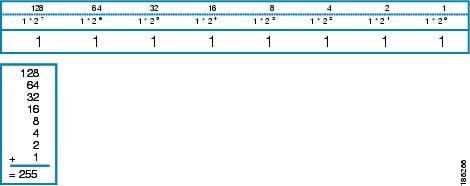
A value in binary is represented by the number (0 or 1) in each position multiplied by the number 2 to the power of the position of the number in sequence, starting with 0 and increasing to 7, working right to left. The figure below is an example of an 8-digit binary number.
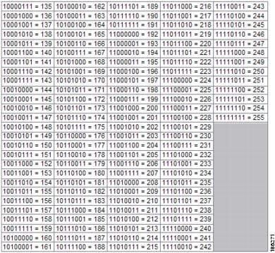
The figure below provides binary to decimal number conversion for 0 through 134.

The figure below provides binary to decimal number conversion for 135 through 255.
IP Address Structure
An IP host address identifies a device to which IP packets can be sent. An IP network address identifies a specific network segment to which one or more hosts can be connected. The following are characteristics of IP addresses:
- IP addresses are 32 bits long
- IP addresses are divided into four sections of one byte (octet) each
- IP addresses are typically written in a format known as dotted decimal
The table below shows some examples of IP addresses.
| Table 1 | Examples of IP Addresses |
|
IP Addresses in Dotted Decimal |
IP Addresses in Binary |
|---|---|
|
10.34.216.75 |
00001010.00100010.11011000.01001011 |
|
172.16.89.34 |
10101100.00010000.01011001.00100010 |
|
192.168.100.4 |
11000000.10101000.01100100.00000100 |
Note | The IP addresses in the table above are from RFC 1918, Address Allocation for Private Internets . These IP addresses are not routable on the Internet. They are intended for use in private networks. For more information on RFC1918, see http://www.ietf.org/rfc/rfc1918.txt . |
IP addresses are further subdivided into two sections known as network and host. The division is accomplished by arbitrarily ranges of IP addresses to classes. For more information see RFC 791 Internet Protocol at http://www.ietf.org/rfc/rfc0791.txt .
IP Address Classes
In order to provide some structure to the way IP addresses are assigned, IP addresses are grouped into classes. Each class has a range of IP addresses. The range of IP addresses in each class is determined by the number of bits allocated to the network section of the 32-bit IP address. The number of bits allocated to the network section is represented by a mask written in dotted decimal or with the abbreviation /n where n = the numbers of bits in the mask.
The table below lists ranges of IP addresses by class and the masks associated with each class. The digits in bold indicate the network section of the IP address for each class. The remaining digits are available for host IP addresses. For example, IP address 10.90.45.1 with a mask of 255.0.0.0 is broken down into a network IP address of 10.0.0.0 and a host IP address of 0.90.45.1.
| Table 2 | IP Address Ranges by Class with Masks |
|
Class |
Range |
|---|---|
|
A (range/mask in dotted decimal) |
0 .0.0.0 to 127.0.0.0/8 (255.0.0.0) |
|
A (range in binary) |
00000000 .00000000.00000000.00000000 to01111111.00000000.00000000.00000000 |
|
A (mask in binary) |
11111111.00000000.00000000.00000000/8 |
|
B (range/mask in dotted decimal) |
128 .0.0.0 to 191.255.0.0/16 (255.255.0.0) |
|
B (range in binary) |
10000000 .00000000.00000000.00000000 to10111111.11111111.00000000.00000000 |
|
B (mask in binary) |
11111111 .11111111.00000000.00000000/16 |
|
C (range/mask in dotted decimal) |
192 .0.0.0 to 223.255.255.0/24 (255.255.255.0) |
|
C (range in binary) |
11000000 .00000000.00000000.00000000 to11011111.11111111.11111111.00000000 |
|
C (mask in binary) |
11111111.11111111.11111111.0000000/24 |
|
D1 (range/mask in dotted decimal) |
224 .0.0.0 to 239.255.255.255/32 (255.255.255.255) |
|
D (range in binary) |
11100000 .00000000.00000000.00000000 to11101111.11111111.11111111.11111111 |
|
D (mask in binary) |
11111111.11111111.11111111.11111111/32 |
|
E2 (range/mask in dotted decimal) |
240 .0.0.0 to 255.255.255.255/32 (255.255.255.255) |
|
E (range in binary) |
11110000 .00000000.00000000.00000000 to11111111.11111111.11111111.11111111 |
|
E (mask in binary) |
11111111.11111111.11111111.11111111/32 |
Note | Some IP addresses in these ranges are reserved for special uses. For more information refer to RFC 3330, Special-Use IP Addresses , at http://www.ietf.org/rfc/rfc3330.txt . |
When a digit that falls within the network mask changes from 1 to 0 or 0 to 1 the network address is changed. For example, if you change 10101100.00010000.01011001.00100010/16 to 10101100.00110000.01011001.00100010/16 you have changed the network address from 172.16.89.34/16 to 172.48.89.34/16.
When a digit that falls outside the network mask changes from 1 to 0 or 0 to 1 the host address is changed. For example, if you change 10101100.00010000.01011001.00100010/16 to 10101100.00010000.01011001.00100011/16 you have changed the host address from 172.16.89.34/16 to 172.16.89.35/16.
Each class of IP address supports a specific range of IP network addresses and IP host addresses. The range of IP network addresses available for each class is determined with the formula 2 to the power of the number of available bits. In the case of class A addresses, the value of the first bit in the 1st octet (as shown in the table above) is fixed at 0. This leaves 7 bits for creating additional network addresses. Therefore there are 128 IP network addresses available for class A (27 = 128).
The number of IP host addresses available for an IP address class is determined by the formula 2 to the power of the number of available bits minus 2. There are 24 bits available in a class A addresses for IP host addresses. Therefore there are 16,777,214 IP hosts addresses available for class A ((224) - 2 = 16,777,214)).
The table below shows the network and host addresses available for each class of IP address.
| Table 3 | Network and Host Addresses Available for Each Class of IP Address |
|
Class |
Network Addresses |
Host Addresses |
|---|---|---|
|
A |
128 |
16,777,214 |
|
B |
16,3843 |
65534 |
|
C |
2,097,1524 |
254 |
IP Network Subnetting
The arbitrary subdivision of network and host bits in IP address classes resulted in an inefficient allocation of IP space. For example, if your network has 16 separate physical segments you will need 16 IP network addresses. If you use 16 class B IP network addresses, you would be able to support 65,534 hosts on each of the physical segments. Your total number of supported host IP addresses is 1,048,544 (16 * 65,534 = 1,048,544). Very few network technologies can scale to having 65,534 hosts on a single network segment. Very few companies need 1,048,544 IP host addresses. This problem required the development of a new strategy that permitted the subdivision of IP network addresses into smaller groupings of IP subnetwork addresses. This strategy is known as subnetting.
If your network has 16 separate physical segments you will need 16 IP subnetwork addresses. This can be accomplished with one class B IP address. For example, start with the class B IP address of 172.16.0.0 you can reserve 4 bits from the third octet as subnet bits. This gives you 16 subnet IP addresses 24 = 16. The table below shows the IP subnets for 172.16.0.0/20.
| Table 4 | Examples of IP Subnet Addresses using 172.16.0.0/20 |
|
Number |
IP Subnet Addresses in Dotted Decimal |
IP Subnet Addresses in Binary |
|---|---|---|
|
05 |
172.16.0.0 |
10101100.00010000.00000000.00000000 |
|
1 |
172.16.16.0 |
10101100.00010000.00010000.00000000 |
|
2 |
172.16.32.0 |
10101100.00010000.00100000.00000000 |
|
3 |
172.16.48.0 |
10101100.00010000.00110000.00000000 |
|
4 |
172.16.64.0 |
10101100.00010000.01000000.00000000 |
|
5 |
172.16.80.0 |
10101100.00010000.01010000.00000000 |
|
6 |
172.16.96.0 |
10101100.00010000.01100000.00000000 |
|
7 |
172.16.112.0 |
10101100.00010000.01110000.00000000 |
|
8 |
172.16.128.0 |
10101100.00010000.10000000.00000000 |
|
9 |
172.16.144.0 |
10101100.00010000.10010000.00000000 |
|
10 |
172.16.160.0 |
10101100.00010000.10100000.00000000 |
|
11 |
172.16.176.0 |
10101100.00010000.10110000.00000000 |
|
12 |
172.16.192.0 |
10101100.00010000.11000000.00000000 |
|
13 |
172.16.208.0 |
10101100.00010000.11010000.00000000 |
|
14 |
172.16.224.0 |
10101100.00010000.11100000.00000000 |
|
15 |
172.16.240.0 |
10101100.00010000.11110000.00000000 |
When a digit that falls within the subnetwork (subnet) mask changes from 1 to 0 or 0 to 1 the subnetwork address is changed. For example, if you change 10101100.00010000.01011001.00100010/20 to 10101100.00010000.01111001.00100010/20 you have changed the network address from 172.16.89.34/20 to 172.16.121.34/20.
When a digit that falls outside the subnet mask changes from 1 to 0 or 0 to 1 the host address is changed. For example, if you change 10101100.00010000.01011001.00100010/20 to 10101100.00010000.01011001.00100011/20 you have changed the host address from 172.16.89.34/20 to 172.16.89.35/20.
 Timesaver | To avoid having to do manual IP network, subnetwork, and host calculations, use one of the free IP subnet calculators available on the Internet. |
Some people get confused about the terms network address and subnet or subnetwork addresses and when to use them. In the most general sense the term network address means âthe IP address that routers use to route traffic to a specific network segment so that the intended destination IP host on that segment can receive itâ. Therefore the term network address can apply to both non-subnetted and subnetted IP network addresses. When you are troubleshooting problems with forwarding traffic from a router to a specific IP network address that is actually a subnetted network address, it can help to be more specific by referring to the destination network address as a subnet network address because some routing protocols handle advertising subnet network routes differently from network routes. For example, the default behavior for RIP v2 is to automatically summarize the subnet network addresses that it is connected to their non-subnetted network addresses (172.16.32.0/24 is advertised by RIP v2 as 172.16.0.0/16) when sending routing updates to other routers. Therefore the other routers might have knowledge of the IP network addresses in the network, but not the subnetted network addresses of the IP network addresses.

IP Network Address Assignments
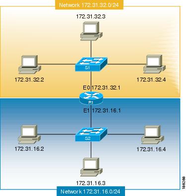
Routers keep track of IP network addresses to understand the network IP topology (layer 3 of the OSI reference model) of the network to ensure that IP traffic can be routed properly. In order for the routers to understand the network layer (IP) topology, every individual physical network segment that is separated from any other physical network segment by a router must have a unique IP network address.
The figure below shows an example of a simple network with correctly configured IP network addresses. The routing table in R1 looks like the table below.
| Table 5 | Routing Table for a Correctly Configured Network |
|
Interface Ethernet 0 |
Interface Ethernet 1 |
|---|---|
|
172.31.32.0/24 (Connected) |
172.31.16.0/24 (Connected) |
The figure below shows an example of a simple network with incorrectly configured IP network addresses. The routing table in R1 looks like the table below. If the PC with IP address 172.31.32.3 attempts to send IP traffic to the PC with IP address 172.31.32.54, router R1 cannot determine which interface that the PC with IP address 172.31.32.54 is connected to.
| Table 6 | Routing Table in Router R1 for an Incorrectly Configured Network (Example 1) |
|
Ethernet 0 |
Ethernet 1 |
|---|---|
|
172.31.32.0/24 (Connected) |
172.31.32.0/24 (Connected) |
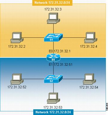
To help prevent mistakes as shown in the figure above, Cisco IOS-based networking devices will not allow you to configure the same IP network address on two or more interfaces in the router when IP routing is enabled.
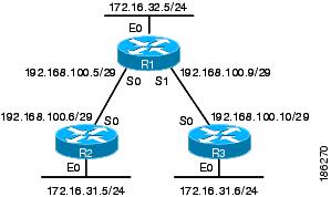
The only way to prevent the mistake shown in the figure below, where 172.16.31.0/24 is used in R2 and R3, is to have very accurate network documentation that shows where you have assigned IP network addresses.
| Table 7 | Routing Table in Router R1 for an Incorrectly Configured Network (Example 2) |
|
Ethernet 0 |
Serial 0 |
Serial 1 |
|---|---|---|
|
172.16.32.0/24 (Connected) |
192.168.100.4/29 (Connected) 172.16.31.0/24 RIP |
192.168.100.8/29 (Connected) 172.16.31.0/24 RIP |
For a more thorough explanation of IP routing, see the "Related Documents" section for a list of documents related to IP routing.
Classless Inter-Domain Routing
Due to the continuing increase in internet use and the limitations on how IP addresses can be assigned using the class structure shown in the table above, a more flexible method for allocating IP addresses was required. The new method is documented in RFC 1519 Classless Inter-Domain Routing (CIDR): an Address Assignment and Aggregation Strategy. CIDR allows network administrators to apply arbitrary masks to IP addresses to create an IP addressing plan that meets the requirements of the networks that they administrate.
For more information on CIDR, refer to RFC 1519 at http://www.ietf.org/rfc/rfc1519.txt.
Prefixes
The term prefix is often used to refer to the number of bits of an IP network address that are of importance for building routing tables. If you are using only classful (strict adherence to A, B, and C network address boundaries) IP addresses, the prefixes are the same as the masks for the classes of addresses. For example, using classful IP addressing, a class C IP network address such as 192.168.10.0 uses a 24-bit mask (/24 or 255.255.255.0) and can also be said to have a 24-bit prefix.
If you are using CIDR, the prefixes are arbitrarily assigned to IP network addresses based on how you want to populate the routing tables in your network. For example, a group of class C IP addresses such as 192.168.10.0, 192.168.11.0, 192.168.12.0, 192.168.13.0 can be advertised as a single route to 192.168.0.0 with a 16-bit prefix (192.168.0.0/16). This results in a 4:1 reduction in the number of routes that the routers in your network need to manage.
How to Configure IP Addresses
- Establishing IP Connectivity to a Network by Assigning an IP Address to an Interface
- Increasing the Number of IP Hosts that Are Supported on a Network by Using Secondary IP Addresses
- Maximizing the Number of Available IP Subnets by Allowing the Use of IP Subnet Zero
- Specifying the Format of Network Masks
- Using IP Unnumbered Interfaces on Point-to-Point WAN Interfaces to Limit Number of IP Addresses Required
- Using IP addresses with 31-Bit Prefixes on Point-to-Point WAN Interfaces to Limit Number of IP Addresses Required
Establishing IP Connectivity to a Network by Assigning an IP Address to an Interface
DETAILED STEPS
Increasing the Number of IP Hosts that Are Supported on a Network by Using Secondary IP Addresses
If you have a situation in which you need to connect more IP hosts to a network segment and you have used all of the available IP host addresses for the subnet to which you have assigned the segment, you can avoid having to readdress all of the hosts with a different subnet by adding a second IP network address to the network segment.
Perform this task to configure a secondary IP address on an interface.
DETAILED STEPS
Troubleshooting Tips
The following commands can help troubleshoot IP addressing:
- show ip interface --Displays the IP parameters for the interface.
- show ip route connected --Displays the IP networks the networking device is connected to.
What to Do Next
If your network has two or more routers and you have already configured a routing protocol, make certain that the other routers can reach the new IP network that you assigned. You might need to modify the configuration for the routing protocol on the router so that it advertises the new network. Consult the Cisco IOS IP Routing: Protocol-Independent Configuration Guide for information on configuring routing protocols.
Maximizing the Number of Available IP Subnets by Allowing the Use of IP Subnet Zero
If you using subnetting in your network and you are running out of network addresses, you can configure your networking device to allow the configuration of subnet zero. This adds one more usable network address for every subnet in your IP addressing scheme. The table above shows the IP subnets (including subnet 0) for 172.16.0.0/20.
Perform this task to enable the use of IP subnet zero on your networking device.
DETAILED STEPS
Specifying the Format of Network Masks
By default, show commands display an IP address and then its netmask in dotted decimal notation. For example, a subnet would be displayed as 131.108.11.55 255.255.255.0.
You might find it more convenient to display the network mask in hexadecimal format or bit count format instead. The hexadecimal format is commonly used on UNIX systems. The previous example would be displayed as 131.108.11.55 0XFFFFFF00.
The bit count format for displaying network masks is to append a slash (/) and the total number of bits in the netmask to the address itself. The previous example would be displayed as 131.108.11.55/24.
- Specifying the Format in Which Netmasks Appear for the Current Session
- Specifying the Format in Which Netmasks Appear for an Individual Line
Specifying the Format in Which Netmasks Appear for the Current Session
DETAILED STEPS
Specifying the Format in Which Netmasks Appear for an Individual Line
DETAILED STEPS
Using IP Unnumbered Interfaces on Point-to-Point WAN Interfaces to Limit Number of IP Addresses Required
If you have a limited number of IP network or subnet addresses and you have point-to-point WANs in your network, you can use the IP Unnumbered Interfaces feature to enable IP connectivity on the point-to-point WAN interfaces without actually assigning an IP address to them.
Perform this task to configure the IP Unnumbered Interfaces feature on a point-to-point WAN interface.
IP Unnumbered Feature
The IP Unnumbered Interfaces feature enables IP processing on a point-to-point WAN interface without assigning it an explicit IP address. The IP unnumbered point-to-point WAN interface uses the IP address of another interface to enable IP connectivity, which conserves network addresses.
DETAILED STEPS
Using IP addresses with 31-Bit Prefixes on Point-to-Point WAN Interfaces to Limit Number of IP Addresses Required
You can reduce the number of IP subnets used by networking devices to establish IP connectivity to point-to-point WANs that they are connected to by using IP Addresses with 31-bit Prefixes as defined in RFC 3021.
Perform this task to configure an IP address with a 31-bit prefix on a point-to-point WAN interface.
RFC 3021
Prior to RFC 3021, Using 31-bit Prefixes on IPv4 Point-to-Point Links , many network administrators assigned IP address with a 30-bit subnet mask (255.255.255.252) to point-to-point interfaces to conserve IP address space. Although this practice does conserve IP address space compared to assigning IP addresses with shorter subnet masks such as 255.255.255.240, IP addresses with a 30-bit subnet mask still require four addresses per link: two host addresses (one for each host interface on the link), one all-zeros network address, and one all-ones broadcast network address.
The table below shows an example of the four IP addresses that are created when a 30-bit (otherwise known as 255.255.255.252 or /30) subnet mask is applied to the IP address 192.168.100.4. The bits that are used to specify the host IP addresses in bold.
| Table 8 | Four IP Addresses Created When a 30-Bit Subnet Mask (/30) Is Used |
|
Address |
Description |
Binary |
|---|---|---|
|
192.168.100.4/30 |
All-zeros IP address |
11000000.10101000.01100100.00000100 |
|
192.168.100.5/30 |
First host addresses |
11000000.10101000.01100100.00000101 |
|
192.168.100.6/30 |
Second host address |
11000000.10101000.01100100.00000110 |
|
192.168.100.7/30 |
All-ones broadcast address |
11000000.10101000.01100100.00000111 |
Point-to-point links only have two endpoints (hosts) and do not require broadcast support because any packet that is transmitted by one host is always received by the other host. Therefore the all-ones broadcast IP address is not required for a point-to-point interface.
The simplest way to explain RFC 3021 is to say that the use of a 31-bit prefix (created by applying a 31-bit subnet mask to an IP address) allows the all-zeros and all-ones IP addresses to be assigned as host addresses on point-to-point networks. Prior to RFC 3021 the longest prefix in common use on point-to-point links was 30-bits, which meant that the all-zeros and all-ones IP addresses were wasted.
The table below shows an example of the two IP addresses that are created when a 31-bit (otherwise known as 255.255.255.254 or /31) subnet mask is applied to the IP address 192.168.100.4. The bit that is used to specify the host IP addresses in bold
| Table 9 | Two IP Addresses Created When a 31-Bit Subnet Mask (/31) Is Used |
|
Address |
Description |
Binary |
|---|---|---|
|
192.168.100.4/31 |
First host address |
11000000.10101000.01100100.00000100 |
|
192.168.100.5/31 |
Second host address |
11000000.10101000.01100100.00000101 |
The complete text for RFC 3021 is available at http://www.ietf.org/rfc/rfc3021.txt .
You must have classless IP addressing configured on your networking device before you configure an IP address with a 31-bit prefix on a point-to-point interface. Classless IP addressing is enabled by default in many versions of Cisco IOS software. If you are not certain that your networking device has IP classless addressing configured, enter the ip classless command in global configuration mode to enable it.
Note | This task can only be performed on point-to-point (nonmultiaccess) WAN interfaces. |
DETAILED STEPS
Configuration Examples for IP Addresses
- Example Establishing IP Connectivity to a Network by Assigning an IP Address to an Interface
- Example Increasing the Number of IP Hosts that are Supported on a Network by Using Secondary IP Addresses
- Example Using IP Unnumbered Interfaces on Point-to-Point WAN Interfaces to Limit Number of IP Addresses Required
- Example Using IP addresses with 31-Bit Prefixes on Point-to-Point WAN Interfaces to Limit Number of IP Addresses Required
- Example Maximizing the Number of Available IP Subnets by Allowing the Use of IP Subnet Zero
Example Establishing IP Connectivity to a Network by Assigning an IP Address to an Interface
The following example configures an IP address on three interfaces:
!
interface FastEthernet0/0
 no shutdown
 ip address 172.16.16.1 255.255.240.0
!
interface FastEthernet0/1
 no shutdown
 ip address 172.16.32.1 255.255.240.0
!
interface FastEthernet0/2
 no shutdown
 ip address 172.16.48.1 255.255.240.0
!
Example Increasing the Number of IP Hosts that are Supported on a Network by Using Secondary IP Addresses
The following example configures secondary IP addresses on three interfaces:
!
interface FastEthernet0/0
 no shutdown
 ip address 172.16.16.1 255.255.240.0
 ip address 172.16.32.1 255.255.240.0 secondary
!
!
interface FastEthernet0/1
 no shutdown
 ip address 172.17.16.1 255.255.240.0
 ip address 172.17.32.1 255.255.240.0 secondary
!
!
interface FastEthernet0/2
 no shutdown
 ip address 172.18.16.1 255.255.240.0
 ip address 172.18.32.1 255.255.240.0 secondary
!
Example Using IP Unnumbered Interfaces on Point-to-Point WAN Interfaces to Limit Number of IP Addresses Required
The following example configures the unnumbered IP feature on three interfaces:
!
interface FastEthernet0/0
 no shutdown
 ip address 172.16.16.1 255.255.240.0
!
interface serial0/0
 no shutdown
 ip unnumbered fastethernet0/0
!
interface serial0/1
 no shutdown
 ip unnumbered fastethernet0/0
!
interface serial0/2
 no shutdown
 ip unnumbered fastethernet0/0
!
Where to Go Next
If your network has two or more routers and you have not already configured a routing protocol, consult the Cisco IOS IP Routing Protocols Configuration Guide, Release 12.4T, for information on configuring routing protocols.
Additional References
Related Documents
|
Related Topic |
Document Title |
|---|---|
|
Cisco IOS commands |
|
|
IP addressing commands: complete command syntax, command mode, command history, defaults, usage guidelines, and examples |
Cisco IOS IP Addressing Services Command Reference |
|
Fundamental principles of IP addressing and IP routing |
IP Routing Primer ISBN 1578701082 |
MIBs
RFCs
|
RFC6 |
Title |
|---|---|
|
RFC 791 |
Internet Protocol |
|
RFC 1338 |
Classless Inter-Domain Routing (CIDR): an Address Assignment and Aggregation Strategy http://www.ietf.org/rfc/rfc1519.txt |
|
RFC 1466 |
Guidelines for Management of IP Address Space http://www.ietf.org/rfc/rfc1466.txt |
|
RFC 1716 |
Towards Requirements for IP Routers http://www.ietf.org/rfc/rfc1716.txt |
|
RFC 1918 |
Address Allocation for Private Internets http://www.ietf.org/rfc/rfc1918.txt |
|
RFC 3330 |
Special-Use IP Addresses http://www.ietf.org/rfc/rfc3330.txt |
Technical Assistance
|
Description |
Link |
|---|---|
|
The Cisco Support and Documentation website provides online resources to download documentation, software, and tools. Use these resources to install and configure the software and to troubleshoot and resolve technical issues with Cisco products and technologies. Access to most tools on the Cisco Support and Documentation website requires a Cisco.com user ID and password. |
Feature Information for IP Addresses
The following table provides release information about the feature or features described in this module. This table lists only the software release that introduced support for a given feature in a given software release train. Unless noted otherwise, subsequent releases of that software release train also support that feature.
Use Cisco Feature Navigator to find information about platform support and Cisco software image support. To access Cisco Feature Navigator, go to www.cisco.com/go/cfn. An account on Cisco.com is not required.
| Table 10 | Feature Information for IP Addresses |
|
Feature Name |
Releases |
Feature Information |
|---|---|---|
|
Classless Inter-Domain Routing |
10.0 |
CIDR is a new way of looking at IP addresses that eliminates the concept of classes (class A, class B, and so on). For example, network 192.213.0.0, which is an illegal class C network number, is a legal supernet when it is represented in CIDR notation as 192.213.0.0/16. The /16 indicates that the subnet mask consists of 16 bits (counting from the left). Therefore, 192.213.0.0/16 is similar to 192.213.0.0 255.255.0.0. The following command was introduced or modified: ip classless. |
|
IP Subnet Zero |
10.0 |
In order to conserve IP address space IP Subnet Zero allows the use of the all-zeros subnet as an IP address on an interface, such as configuring 172.16.0.1/24 on Fast Ethernet 0/0. The following command was introduced or modified: ip subnet-zero. |
|
IP Unnumbered Interfaces |
10.0 |
In order to conserve IP address space, IP unnumbered interfaces use the IP address of another interface to enable IP connectivity. The following command was introduced or modified: ip unnumbered. |
|
Using 31-bit Prefixes on IP Point-to-Point Links |
12.0(14)S 12.2(4)T |
In order to conserve IP address space on the Internet, a 31-bit prefix length allows the use of only two IP addresses on a point-to-point link. Previously, customers had to use four IP addresses or unnumbered interfaces for point-to-point links. |
Cisco and the Cisco Logo are trademarks of Cisco Systems, Inc. and/or its affiliates in the U.S. and other countries. A listing of Cisco's trademarks can be found at www.cisco.com/go/trademarks. Third party trademarks mentioned are the property of their respective owners. The use of the word partner does not imply a partnership relationship between Cisco and any other company. (1005R)
Any Internet Protocol (IP) addresses and phone numbers used in this document are not intended to be actual addresses and phone numbers. Any examples, command display output, network topology diagrams, and other figures included in the document are shown for illustrative purposes only. Any use of actual IP addresses or phone numbers in illustrative content is unintentional and coincidental.