Feedback
Table Of Contents
Introducing Cisco IPICS and the PMC Application
System Requirements for the PMC Application
Introducing Cisco IPICS and the PMC Application
This chapter provides an overview of the components that are used in the Cisco IPICS solution. It also documents system requirements for the PMC application and important information that you need to know about server and user interactions.
This chapter includes the following topics:
•
System Requirements for the PMC Application
Overview of Cisco IPICS
This section provides an overview of Cisco IPICS and the PMC application; it includes the following topics:
•
Introduction
The Cisco IPICS solution provides a cost-effective and highly-efficient IP standards-based solution to enable voice interoperability among disparate systems. By interconnecting voice channels, talk groups, and virtual talk groups (VTGs), Cisco IPICS bridges communications from radio networks to the Cisco IPICS Push-to-Talk Management Center (PMC) PC application and other end-user devices, such as supported models of Cisco Unified IP Phones, mobile phones, and public switched telephone network (PSTN) phones.
To provide this functionality, Cisco IPICS uses several components and technologies, including the Cisco IPICS server and the PMC, the Land Mobile Radio (LMR) gateway, Cisco gateways and routers, Voice over IP (VoIP) technology, and router media services (RMS) functionality for channel mixing.
Cisco IPICS extends the reach of traditional communications networks and includes additional capability by integrating dial-in/dial-out and notification functionality via email, pager notification, and Short Message Service (SMS). Through the use of integrated, web-based system management software, the Cisco IPICS solution facilitates the tasks that are associated with operations and command and control to simplify communications and enable dynamic resource management for users, channels, and VTGs.
Support is included for tone-controlled radios with enhanced functionality in the LMR gateway that enables support for RFC 2198 and RFC 2833 standard messages. The PMC includes a radio console skin that provides support for channel selector buttons that you use for signaling, to change channels, or control tone sequences. To enable this functionality, the PMC sends RFC 2198 and RFC 2833 packets on a per-channel basis. At the LMR gateway, the packets are converted into audible tones and output via the configured ear and mouth (E&M) interface to the physical radio to provide tone control for radios. For more information, see the "Communicating with Cisco IPICS Users via Tone-Controlled Radios" section on page 4-32.
The following examples portray typical customers who use disparate networks:
•
•
Benefits of Cisco IPICS
For these customers, the Cisco IPICS solution provides the following benefits:
•
•
Related Topics
•
Cisco IPICS System Components
The Cisco IPICS solution comprises the following major components, as described in Table 1-1:
Table 1-1 Cisco IPICS System Components
Cisco IPICS Server
This component provides the core functionality of the Cisco IPICS system. The Cisco IPICS server software runs on the Cisco Linux operating system on selected Cisco Media Convergence Server (MCS) platforms. (Refer to the Cisco IPICS Compatibility Matrix for information about the servers that Cisco IPICS supports.)
The Cisco IPICS server software includes the Cisco IPICS Administration Console, which is an incident management framework graphical user interface (GUI) that enables dynamic resource management for users, channels, and VTGs. (In Cisco IPICS, VTGs combine one or more channels and/or users.) By using this GUI, authorized Cisco IPICS users can manage the system configuration and authentication and security services, policies and privileges, and database information.
The server also enables control of the configuration of the media resources that are installed in the router and which are used for audio mixing capabilities.
In addition, the server hosts the Cisco IPICS policy engine (hereafter referred to as policy engine), which enables telephony dial functionality and maintains responsibility for the management and execution of policies and user notifications.
For more information about the role of the Cisco IPICS server, see the "The Role of the Cisco IPICS Server" section on page 3-8.
For more information about the various user roles that Cisco IPICS supports, see the "Cisco IPICS User Roles" section.
Push-to-Talk Management Center (PMC)
The PMC is a PC-based audio application that simulates a handheld radio to enable PTT functionality for PC users. It connects Cisco IPICS users via an IP network to enable participation in and monitor of one or more talk groups or VTGs at the same time. The PMC is supported for use only with the Windows XP operating system.
The PMC includes several skins that allow PMC users to change the appearance of the PMC user interface. These skins may include Cisco-provided skins or a custom skin.
For information about PMC hardware and software requirements, see the "System Requirements for the PMC Application" section.
Gateways
This component includes LMR gateways, which functionality is usually installed as an additional feature in a supported Cisco router. LMR gateways provide voice interoperability between radio and non-radio networks by bridging radio frequencies to IP multicast streams. They also provide keying signals to key radio transmissions.
Cisco IPICS leverages the Cisco Hoot 'n' Holler feature, which is enabled in specific Cisco IOS versions, to provide radio integration into the Cisco IPICS solution. LMR is integrated by providing an ear and mouth (E&M) interface to a radio or other PTT devices, such as Nextel phones. Configured as a voice port, this interface provides the appropriate electrical interface to the radio. You configure this voice port with a connection trunk entry that corresponds to a voip dial peer, which in turn associates the connection to a multicast address. This configuration allows you to configure a corresponding channel in Cisco IPICS, using the same multicast address, which enables Cisco IPICS to provide communication paths between the desired endpoints.
Router Media Service
The Router Media Service (RMS) component enables the PMC to remotely attach to a VTG. This component also provides support, through its loopback functionality, for remotely attaching (combining) two or more VTGs. The RMS mixes multicast channels in support of VTGs as well as PMC SIP-based (unicast) connections to a multicast channel or VTG. In addition, the RMS component provides support for unicast M1:U12:M2 connection trunks. The RMS can be installed as a stand-alone component (RMS router) or as an additional feature that is installed in the LMR gateway.
For a list of RMS routers and Cisco IOS versions that Cisco IPICS supports for use as an RMS, refer to the Cisco IPICS Compatibility Matrix. (Each supported Cisco IOS version includes the Cisco Hoot `n' Holler feature.)
Networking Components
The Cisco IPICS solution may include some or all of the following network components, depending on the functionality that you require: routers, gateways, switches, firewalls, mobile access routers, wireless access points, and bridges.
Cisco Unified Communications Manager (CallManager) and VoIP Services
Cisco IPICS provides support for SIP-based interoperability with supported versions of Cisco Unified Communications Manager (formerly known as Cisco CallManager) and a Cisco router that is running a supported version of Cisco IOS with Cisco Unified Communications Manager Express (formerly known as Cisco Unified CallManager Express) to enable selected Cisco Unified IP Phone models to participate in channels and VTGs.
These applications help extend the reach of PTT technology to the IP network by enabling these phones to work with Cisco IPICS as IP phone multicast client devices. They also serve as the SIP provider for the Cisco IPICS policy engine to provide SIP telephony support for calls to and from the dial engine.
Note
Cisco IPICS User Roles
Every Cisco IPICS user is assigned one or more roles. The Cisco IPICS solution authorizes access to different features based on the role that is assigned to each user. In this way, roles help to provide system security.
Table 1-2 describes the user roles that Cisco IPICS supports. For more information about how these roles interact, see the "Cisco IPICS Server-PMC Interaction Scenario" section on page 3-3.
Related Topics
•
•
•
About the PMC Application
This section contains information about the PMC application and it includes the following topics:
•
The PMC application provides the interface that enables push-to-talk audio communications. By using a simplified GUI, the PMC allows simultaneous monitoring and participation in one or more channels or VTGs at the same time.
The Cisco IPICS operator enables your user profile for access to the PMC application.
After you have been authorized to use the system, you can download the PMC software from the Cisco IPICS server and install it on your PMC client machine. For more information, see the "Downloading and Installing the PMC Application" section on page 2-4.
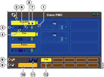
See Figure 1-1 for an illustration of the PMC application. This example shows a partial illustration of the PMC that has been configured for mouse-based use with the 18-channel advanced feature console skin.
See Figure 1-2 for a partial illustration of the PMC that has been configured for mouse-based use with the 36-channel radio console skin.
Cisco IPICS includes additional skins, with different features and functionality, that you may configure for use. For more information, see the "Configuring the PMC Skins" section on page 5-2.
Figure 1-1 PMC with Partially-Displayed Advanced Console Skin
Activation/
Deactivation Button
Click this button to activate a channel; click again to deactivate. The activation button highlights and changes orientation when you activate it.
For more information about the PMC buttons, see the "Activating the PMC Buttons" section on page 4-13.
PTT Channel Button with Receive Indicator and Latch Indicator
PTT Channel with Warning Indicator
Click the PTT channel button with your mouse, or push, and hold it to talk. When you are done talking, release the left mouse button to return to listen-only mode.
The PTT channel button highlights in a different color when the PMC is in transmission mode. (The touch screen and the radio skins include a transmit indicator that blinks red when the PMC transmits traffic. For more information about caveats that pertain to the touch screen skins, see the "Touch Screen Skin Caveats" section on page 5-7. For more information about the caveats that pertain to the radio skin, see the "Radio Skin Caveats" section on page 5-7.)
The PTT channel button includes a receive indicator, which blinks green when the PMC receives traffic. For more information about traffic activity indicators, see the "Traffic Activity" section on page 4-45.
This button may include a latch indicator. If you have permission to use the latch functionality, you can latch this channel to talk on one or more channels at the same time. To latch, or lock in, the PTT channel, click the latch indicator that displays to the right of the PTT channel button. To clear the latch, click the latch indicator or click the PTT button to release and return to listen-only mode. For more information about using the latch functionality, see the "Using the Latch Functionality" section on page 4-17.
Note
Channel Select Check Box
Check or uncheck this check box to select or deselect the channel for PTT communications. For more information about using the channel select check box, see the "Selecting One or More Channels and Using the All Talk Channel" section on page 4-25.
Voice Replay Controls
Use the voice replay functionality to play back buffered voice transmissions and to view graphical representation of this functionality.
Note
For more information about the voice replay feature, see the "Using the Voice Replay Feature" section on page 4-42.
Volume Up Button
Click this button to increase the volume on the channel.
Volume Down Button
Click this button to decrease the volume on the channel.
Volume Level Indicator Bar
This bar shows the current volume level on the channel in a graphical format. This indicator represents the changes that you make by clicking the volume up and volume down buttons.
Server Status Connectivity Indicator
This connectivity indicator specifies your connectivity status with the server.
•
•
Note
Menu Button
Click the menu button to access the PMC settings menus and online help. For more information, see the "Configuring the PMC End-User Interface" section on page 5-1 and the "Accessing Online Help" section on page 4-13.
All Talk Channel Button
Click the All Talk channel to simultaneously talk on all of the channels that you selected. For more information, see the "End-user Features and Interactions" section on page 4-20.
Select All and Deselect All Buttons
Click the Select All (multiselect) button to select all channels that are assigned to you; click the Deselect All button deselect all channels. For more information about selecting multiple channels, see the "Selecting One or More Channels and Using the All Talk Channel" section on page 4-25.
Alert Tone Buttons
Use these buttons to play out alert tones on one or more channels on the PMC. The PMC plays out alert tones only on the channel(s) that you select. For more information, see the "Playing out Alert Tones" section on page 4-26.
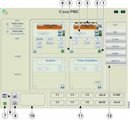
Figure 1-2 shows a partial illustration of the PMC that has been configured for mouse-based use with the 36-channel radio console skin.
Figure 1-2 PMC with Partially-Displayed Radio Console Skin
Activation/
Deactivation ButtonClick this button to activate a channel; click again to deactivate. The activation button highlights and changes orientation when you activate it.
For more information about the PMC buttons, see the "Activating the PMC Buttons" section on page 4-13.
Volume Up and Volume Down Buttons and Volume Indicator
Click these buttons to increase or decrease the volume on the channel. The volume indicator reflects the current volume level on the channel in a graphical format.
PTT Channel Button with Receive and Latch Indicators
Click the PTT channel button with your mouse, or push, and hold it to talk. When you are done talking, release the left mouse button to return to listen-only mode.
The PTT channel button highlights in a different color when the PMC is in transmission mode. The PTT channel button includes a receive indicator, which blinks green when the PMC is receiving traffic. The radio channel button also includes a latch indicator and a transmit indicator, which blinks when you transmit traffic.
To latch, or lock in, the PTT radio channel, click the latch indicator that displays to the right of the PTT channel button. To clear the latch, click the latch indicator or click the PTT button to release and return to listen-only mode.
Voice Replay Controls
Use the voice replay functionality to play back buffered voice transmissions and to view graphical representation of this functionality.
When you use the radio console skin, the voice replay feature records and plays back audio according to the channel that was tuned (active) at the time of capture.
Note
For more information about the voice replay feature, see the "Using the Voice Replay Feature" section on page 4-42.
Channel Selector Buttons
Click to control radio channel functionality, such as tuning a channel to a different frequency or generating a specific tone to invoke an action on the radio. These buttons may consist of channel selector buttons, control buttons, or signal buttons. The PMC can display a maximum of nine buttons per radio channel.
For more information about using tone-controlled radios with the PMC, see the "Communicating with Cisco IPICS Users via Tone-Controlled Radios" section on page 4-32.
Channel Select Check Box
Check or uncheck this check box to select or deselect the channel for PTT communications. For more information about using the channel select check box, see the "Selecting One or More Channels and Using the All Talk Channel" section on page 4-25.
Server Status Connectivity Indicator
This connectivity indicator displays your connectivity status with the server.
•
•
Note
Menu Button
Click the menu button to access the PMC settings menus and online help. For more information, see the "Configuring the PMC End-User Interface" section on page 5-1 and the "Accessing Online Help" section on page 4-13.
Select All and Deselect All Buttons
Click the Select All (multiselect) button to select all channels that are assigned to you; click the Deselect All button deselect all channels. For more information about selecting multiple channels, see the "Selecting One or More Channels and Using the All Talk Channel" section on page 4-25.
All Talk Channel Button
Click the All Talk channel to simultaneously talk on all of the channels that you selected. For more information, see the "End-user Features and Interactions" section on page 4-20.
Alert Tone Buttons
Use these buttons to play out alert tones on one or more channels on the PMC. The PMC plays out alert tones only on the channel(s) that you select. For more information, see the "Playing out Alert Tones" section on page 4-26.
Region Tabs
Click the tabs that display along the right side of the PMC to access different radio views.
Note
For more information, see the "Communicating with Cisco IPICS Users via Tone-Controlled Radios" section on page 4-32.
Tip
Note
The PMC GUI includes buttons that allow you to interact with the Cisco IPICS server. It also includes various indicators to enable visibility of the connection status of the server and inform you about activities such as transmission status, channel states and activity, and volume level indicators.
The PMC GUI includes the PTT channel button, and other buttons, such as the activation button and buttons to control the volume level. Some skins include additional functionality, such as radio channel control buttons, voice replay controls, alert tone buttons, the All Talk button, multiselect channel check boxes, and channel selector buttons; be aware that you must have permission to use some of these features.
The GUI also includes an indicator that blinks when you receive traffic; when you transmit traffic, the PTT channel button highlights and changes color to indicate transmission. (The touch screen and the radio skins also include an indicator that blinks red when you transmit.) See the "Traffic Activity" section on page 4-45 for more information about these indicators.
Tip
When a channel has been activated, the PTT button displays on the PMC in a highlighted color that is based on the configuration in the Cisco IPICS server.
Note
Because the Cisco IPICS server controls the configuration of the PMC application, PMC users have limited access to the configuration parameters; however, Cisco IPICS includes the ability for PMC users to modify some of the configuration elements, such as the PMC GUI skins for mouse-based or touch screen-based display and key mapping. For additional information about end-user features, see the "End-user Features and Interactions" section on page 4-20. For information about configuring the end-user interface, see Chapter 5, "Configuring the PMC Application."
Browser Support
You install the PMC application on your local PC by downloading the software from the Cisco IPICS server upon successful user authentication. Cisco IPICS supports secure Internet access to the server by providing support for the following browser:
•
After successful software download and installation, you log in to the PMC application on your PC. See Chapter 2, "Installing and Upgrading the PMC Application," for additional information about installing and launching the PMC application.
Work Flow Activities
The following activities occur when you use the Cisco IPICS system:
1.
2.
3.
4.
Note
PMC Application Usage Caveats
Be aware of the following caveats when you use the PMC application with Cisco IPICS:
•
•
•
•
•
•
•
Tip
•
•
•
•
Caution
For detailed information about using and configuring the PMC application, See Chapter 4, "Using the PMC Application" and Chapter 5, "Configuring the PMC Application."
Related Topics
•
•
•
•
•
•
•
Architecture/Deployment
A Cisco IPICS server-client deployment consists of a Cisco IPICS server and multiple PMC client systems. The PMC client systems connect to the Cisco IPICS server through a wired or wireless network. Additional components, such as routers and gateways, enable interoperability and additional capabilities. (See Figure 3-1 on page 3-2 for an illustration of this interoperability.)
The PMC is a network-installable application that is remotely managed by the Cisco IPICS server. An authenticated and authorized user can perform the PMC installation via a secure Web login to the Cisco IPICS server. After the PMC is installed, any valid and authorized Cisco IPICS user can log in to the PMC application. The server validates the user login credentials.
As a part of the login process, all user configuration information is downloaded and stored in conjunction with the login credentials. If the PMC becomes disconnected from the Cisco IPICS server, a user with a valid login may continue to use the application in offline mode.
The Cisco IPICS architecture includes centralized management of the PMC application, and specifically, the centralized (role-based) definition of the VTGs in the server. (This model compares to other PTT end-device models where the end-user defines the VTGs or uses a point-to-point session establishment mechanism.)
The fundamental design of the PMC is to present the end-user with channels and VTGs, as managed by the Cisco IPICS dispatcher, and to provide users with the tools that they need to use these channels in an efficient manner.
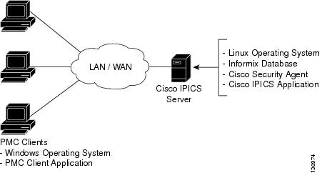
Figure 1-3 shows a simplified version of a Cisco IPICS deployment by illustrating the interaction between the Cisco IPICS server and the PMC components.
Figure 1-3 Cisco IPICS Deployment
The following example represents a simplified flow that occurs between the Cisco IPICS server, the PMC, and other associated components:
1.
2.
3.
4.
5.
a.
b.
For more information about locations and types of connections, see the "Location Support" section on page 3-20.
6.
7.
Related Topics
•
System Requirements for the PMC Application
This section includes information about hardware and software requirements for the PMC application, as well as pertinent caveats.
Hardware Requirements
The PMC application requires the following minimum hardware, as shown in Table 1-3. These requirements are dependent on the number of active PMC channels that you use.
Note
Software Requirements
Table 1-4 includes reference information about the software and applications that you install on your PMC system.
Table 1-4 PMC Systems Software
Windows operating system
Windows XP Professional SP2
Refer to your Microsoft Windows documentation for installation and configuration instructions.
PMC application
Provides access to the PMC features
See Chapter 2, "Installing and Upgrading the PMC Application."
System Interactions
This section includes information about some of the system interactions that occur when you use Cisco IPICS, and includes the following topics:
Server Interactions
Table 1-5 describes the server-level interactions with Cisco IPICS.
Table 1-5 Server-Level Interactions
Configuration Management
The Cisco IPICS server manages the configuration of the PMC and provides regular updates to the PMC. The server controls activities such as user profile management, user authentication, enabling/disabling/muting/unmuting users, enabling/disabling channels, activating/deactivating VTGs, updating the PMC configuration, and managing the PMC logs.
Session Management
The Cisco IPICS server manages the sessions on each of the PMC client machines.
•
•
These updates can include activities such as refreshing the PMC application based on new channel assignments or VTG activations/deactivations and notifying the PMC about new updates to ensure version compatibility.
For more information, see the "Maintaining and Upgrading the PMC Application" section on page 2-16 and "Dynamic Configuration" section on page 4-15.
Login Authentication
The Cisco IPICS server manages the login requests from PMC users. Initial login to the PMC application includes logging through the PMC application in to the Cisco IPICS server. The server then creates a session and identifies the PMC by the unique PMC ID.
If the server goes offline, the PMC user may be able to continue to use the PMC in offline mode as long as the user has made one successful login to the server. The PMC user may also be able to log in to an alternate server. For more information about logging in to alternate servers, see the "PMC Login Procedure" section on page 4-8 and the "Support for Cisco IPICS Recovery" section on page 6-1.
Channel Management
The Cisco IPICS server downloads all of the currently available channels that can be displayed for a particular user based on each PMC session. When the dispatcher adds a user to a particular VTG, the server notifies the PMC of that updated channel availability.
•
•
•
•
For more information, see the "Channel Information" section on page 3-16.
•
User Interactions
Table 1-6 describes the user-level interactions with Cisco IPICS.
Table 1-6 User-Level Interactions
End-User Application Interaction
The Cisco IPICS server provides the list of PMC skins that are available to the PMC application. The server also defines a default skin for the PMC. The PMC stores the skins locally on the PMC user client machine.
The PMC user may choose a different skin by accessing the Settings > Skin menu in the PMC application. The functionality that is available may vary based on the skin that you choose.
See Table 5-1 on page 5-2 for a list of the PMC skins that Cisco IPICS supports.
For more information about configuring the PMC skins, see the "Configuring the PMC Skins" section on page 5-2
End-User Channel Interaction
Channels and VTGs display in various states on the PMC. See Table 4-1 on page 4-19 for a description of the states that Cisco IPICS supports for user interaction.
For more information about using the PMC application, see Chapter 4, "Using the PMC Application."
Related Topics
•
•
•
•
•
•
•
Where to Find More Information