Feedback Feedback
|
Table Of Contents
Troubleshooting ATM PVCs in a WAN Environment
Understanding the Segmentation and Reassembly for AAL5 Frames
Understanding the Basics of Traffic Shaping and Policing
Understanding Variable Bit Rate Nonreal Time (VBR-NRT)
Creating a Mapping Between a Destination Address and PVC
Troubleshooting Connectivity Issues
Troubleshooting PVC Total Connectivity Failure
Before Calling Cisco Systems TAC Team
Troubleshooting ATM PVCs in a WAN Environment
This chapter describes how to troubleshoot ATM problems that are seen when transporting L2 frames/L3 packets over a WAN backbone. The following topics will be reviewed:
•
How are frames or packets segmented into ATM cells?
•
•
Introduction
Asynchronous Transfer Mode (ATM) is a technology that was defined by the ITU-T (formerly known as the CCITT) in the early 1990s. The related standards describe a transport technology in which information is carried in small, fixed-length data units called cells.
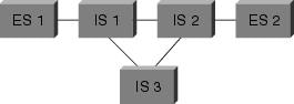
In an ATM network, a clear distinction can be made between the devices supporting the applications, called end systems (ES), and the devices that are only relaying the cells. We will call these relaying devices intermediate systems (IS) or ATM switches. Examples of end systems are routers or LAN Emulation (LANE) modules. Examples of IS are ls1010, 8540MSR, and BPX. An ATM network can therefore be represented as shown in Figure 22-1.
Figure 22-1 ATM Network Representation
Among many other things, ATM defines how to segment and reassemble different types of information. ATM can transport video, voice, and data. Proper quality of service (QoS) is reserved and guaranteed by the ATM network. Because any type of information can be segmented into cells via the related standard, ATM is a flexible tool. Therefore, it can be used in many environments. We will categorize those areas in two main ones:
•
•
–
–
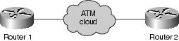
This chapter focuses solely on the last type of ATM connections, in an enterprise environment. End systems in such an environment are routers 99 percent of the time. Therefore, we will use only the word router in the rest of this document. Those routers will exchange packets (see the following note). We will use IP as our reference protocol, so all explanations are valid for other Layer 3 protocols such as IPX and ATALK. As such, from the enterprise point of view, the network is represented in Figure 22-2.
Figure 22-2 Network from the Enterprise Point of View
Note
There must be a traffic contract on the quality of service that will be respected by the enterprise routers and the ATM service provider. Initially, it looks quite simple, with only two devices in the picture and an ATM provider's cloud that is simply not visible from the enterprise point of view. Unfortunately, the problems in this environment are not trivial precisely because you do not have full visibility of the ATM provider's equipment.
Understanding the Segmentation and Reassembly for AAL5 Frames
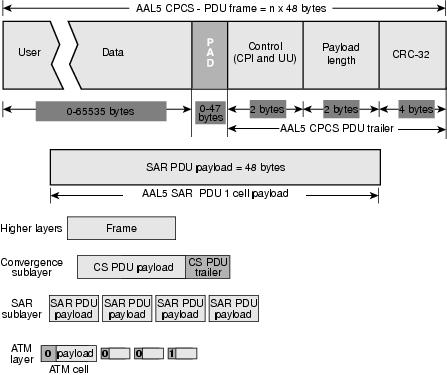
AAL here refers to the ATM Adaptation Layer. As the name suggests, it adapts user information (data, voice, video, and so on) to a format that can be easily divided into ATM cells. The process for AAL5 is described in Figure 22-3.
Figure 22-3 AAL5 Process
At the destination router, the reverse process is being applied. The destination router can easily find which cell is the end of the AAL5 packet with a special bit set to 1 in the cell header.
The whole process is usually implemented in hardware and works efficiently. For now, let's focus on what can go wrong. Two main problems that can arise are described here:
•
•
Let's examine the impact of those two problems at the destination router and determine how we can detect them:
•
•
Note
Whatever the real problem is, a wrong CRC will be detected at the destination. The administrator of the routers can detect this by checking the interface statistics. One CRC error results in an increment of input error counter by 1 (see the previous note). The command show interface atm (module/port) illustrates this behavior:
Medina#sh int atm 3/0ATM3/0 is up, line protocol is upHardware is ENHANCED ATM PAMTU 4470 bytes, sub MTU 4470, BW 149760 Kbit, DLY 80 usec,reliability 255/255, txload 1/255, rxload 1/255Encapsulation ATM, loopback not setKeepalive not supportedEncapsulation(s): AAL54096 maximum active VCs, 2 current VCCsVC idle disconnect time: 300 seconds Signalling vc = 1, vpi = 0, vci = 5UNI Version = 4.0, Link Side = user0 carrier transitionsLast input 00:00:07, output 00:00:07, output hang neverLast clearing of "show interface" counters neverInput queue: 0/75/0 (size/max/drops); Total output drops: 0Queueing strategy: Per VC Queueing5 minute input rate 0 bits/sec, 0 packets/sec5 minute output rate 0 bits/sec, 0 packets/sec104 packets input, 2704 bytes, 0 no bufferReceived 0 broadcasts, 0 runts, 0 giants, 0 throttles32 input errors, 32 CRC, 0 frame, 0 overrun, 0 ignored, 0 abort106 packets output, 2353 bytes, 0 underruns0 output errors, 0 collisions, 1 interface resets0 output buffer failures, 0 output buffers swapped outIf the router has been configured for multiple PVCs, then relying only on the interface global counter might not be very adequate. The input error counter might show that the traffic for multiple PVCs. In this scenario, using the sh atm pvc vpi/vci counters is recommended:
Medina#sh atm pvc 0/36ATM3/0.1: VCD: 4, VPI: 0, VCI: 36VBR-NRT, PeakRate: 2000, Average Rate: 1000, Burst Cells: 32AAL5-LLC/SNAP, etype:0x0, Flags: 0x20, VCmode: 0x0OAM frequency: 0 second(s), OAM retry frequency: 1 second(s), OAM retry frequen)OAM up retry count: 3, OAM down retry count: 5OAM Loopback status: OAM DisabledOAM VC state: Not ManagedILMI VC state: Not ManagedInARP frequency: 15 minutes(s)Transmit priority 2InPkts: 24972, OutPkts: 25032, InBytes: 6778670, OutBytes: 6751812InPRoc: 24972, OutPRoc: 25219, Broadcasts: 0InFast: 0, OutFast: 0, InAS: 0, OutAS: 0InPktDrops: 0, OutPktDrops: 0CrcErrors: 0, SarTimeOuts: 0, OverSizedSDUs: 0OAM cells received: 0F5 InEndloop: 0, F5 InSegloop: 0, F5 InAIS: 0, F5 InRDI: 0F4 InEndloop: 0, F4 InSegloop: 0, F4 InAIS: 0, F4 InRDI: 0OAM cells sent: 0F5 OutEndloop: 0, F5 OutSegloop: 0, F5 OutRDI: 0F4 OutEndloop: 0, F4 OutSegloop: 0, F4 OutRDI: 0OAM cell drops: 0Status: UPIn this output (see the accompanying note), the CRC error counter indicates the number of CRC errors of the CPCS-PDU frame. Both commands were typed on the same router; because no CrcErrors can be seen on the display of statistics for PVC 0/36, we can assume that the input errors of the sh int were due to another PVC.
Note
As a last remark, one input error does not always mean one packet loss. The cell discarded by the ATM provider could be the last one of the frame; therefore, the cell discarded had this special bit set to 1. The only way for the destination to find the frame boundaries is to check this bit. As a result, the destination router concatenates at reassembly time all cells that it receives until it finds a cell with this bit set to 1. If the last cell of a frame is discarded, two CPCS-PDU frames will be lost and will result in only one CRC and length error.
Understanding the Basics of Traffic Shaping and Policing
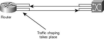
Two basic terms will be used in this chapter: traffic shaping and policing. Traffic shaping refers to an action done by the source of the ATM traffic. Policing refers to actions done by the ATM switches, usually at the provider's side.
Traffic shaping is the action of adapting the cell flow to a specific traffic contract. This is illustrated in Figure 22-4.
Figure 22-4 Traffic Shaping—Adapting the Cell Flow to a Specific Traffic Contract
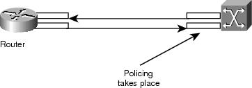
Policing is the action of checking whether the cell flow respects a specific traffic contract. This is illustrated in Figure 22-5.
Figure 22-5 Policing—Checking Whether the Cell Flow Respects a Specific Traffic Contract
These figures are not implying that traffic shaping and policing refer to a common contract and use a similar algorithm. Misconfigured policing or shaping often leads to cells being discarded by the policer. It also happens that even though shaping and policing are both set to the same values, policing starts discarding cells. This is usually the result of a poor shaper or a misbehaving policer.
Understanding Variable Bit Rate Nonreal Time (VBR-NRT)
This chapter provides only an introduction to traffic shaping. If needed, more details can be found in the Traffic Management specification available on the ATM Forum web site.
In ATM, traffic shaping works by inserting equal times between the cells. For example, if an OC-3/STM-1 connection is 155 Mbps, only about 149 Mbps can be used for forwarding ATM cells. (SONET/SDH has approximately 3 percent of overhead.) As a result, the max rate is 353.208 cells (353.208 ¥ 53 ¥ 8 bits can fit in the OC-3c/STM-1 frames payload in a second). If a user requests a connection of 74.5 Mbps (half the line rate), equal spaces of 2.83 usec will be inserted between each cell. 2.83 usec is the time needed to send one cell at OC3c/STM-1 (1/353.208 sec). Because we requested half the line rate, we can send one cell, wait an equal amount of time, and then start over again.
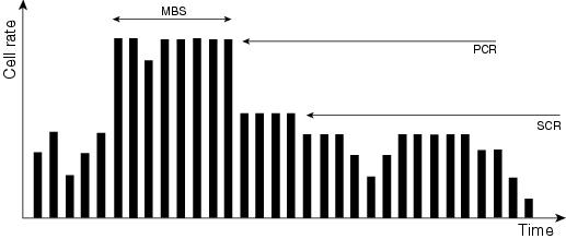
Now that we've described the generic approach, let's focus briefly on the most classic traffic requested, variable bit-rate traffic (VBR) shaping as shown in Figure 22-6.
Figure 22-6 Variable Bit-rate Traffic Shaping
VBR traffic shaping is an effective approach for a bursty network. Parameters used are peak cell rate (PCR), sustainable cell rate (SCR), and maximum burst size (MBS). When a traffic contract has been agreed upon, the ATM network guarantees the transmission of cells within the VBR parameters. The number of cells allowed to exceed SCR is set by MBS and bound by the PCR.
The three traffic contract parameters are defined below:
•
•
•
Creating a Mapping Between a Destination Address and PVC
A common source of problems is the incorrect configuration of the ATM mapping. Basically, after configuring the PVC itself, you must instruct the router on which PVC needs to be used to reach a specific destination. You have three ways to ensure the right mapping:
•
•
•
Troubleshooting Connectivity Issues
The user can often have the feeling that part of the information is being lost between the two routers. The most common symptoms are these:
•
•
Let's concentrate on this second symptom, to help us detect the problem. Say that for every 100 cells transmitted back to back by the source router, the cloud will discard the last one because of policing. This means that if a ping has a data part of 100 bytes, 3 ATM cells will be needed to send it (because 3 ¥ 48 bytes will be needed to contain the ICMP echo request). In practice, this means that the 33 first pings will succeed (more precisely, the first 99 cells will be seen within contract by the provider), but the 34th one will fail because one of its cells will be discarded.
Assuming that we keep the same setup and use 1500-byte packets instead of small ICMP echos (pings), we will need 32 cells to transmit each large packet (32 ¥ 48 = 1536 bytes, the smallest multiple of 48 above the packet size). If the network discards 1 cell out of 100, about one packet out of three or four will be discarded. Raising the packet size is then a simple and efficient way to prove that you have a policing issue.
In practice, you can generate large pings from the router itself:
Medina#pingProtocol [ip]:Target IP address: 10.2.1.2Repeat count [5]: 100Datagram size [100]: 1500Timeout in seconds [2]: 2Extended commands [n]:Sweep range of sizes [n]:Type escape sequence to abort.Sending 100, 1500-byte ICMP Echos to 10.2.1.2, timeout is 2 seconds:!!!.!!.!!!.!!.!!!.!!.!!!.!!.!!!.!!.!!!.!!.!!!.!!.!!!.!!.!!!.!!.!!!.!!.!!!.!!.!!!.!!.!!!.!! .!!!.!!.!Success rate is 72 percent (72/100)If the real problem is related to policing, doing the same test with larger packets will generate a totally different result:
Medina#pingProtocol [ip]:Target IP address: 10.2.1.2Repeat count [5]: 100Datagram size [100]: 3000Timeout in seconds [2]: 2Extended commands [n]:Sweep range of sizes [n]:Type escape sequence to abort.Sending 100, 3000-byte ICMP Echos to 10.2.1.2, timeout is 2 seconds:!.!.!..!.!.!..!.!..!.!...!..!.!.!..!.!.!.!.!.!.!..!..!.!...!..!.!.!..!.!.!..!.!.!..!.!..!. !.!.!..!..!Success rate is 42 percent (42/100)If, after running those tests, you conclude that you are suffering from a policing issue, contact your ATM provider immediately and check the following points:
•
•
If the reason is policing, then what are the traffic parameters? Do they match with the settings on the router?
If the router and the provider do use the same traffic parameters, then there is a real problem. In other words, either the router is not shaping well or the provider is not policing accurately. If this happens, refer to the documentation of the ATM card for known limitations, and check for known bugs. Also keep in mind that no two implementations of traffic shaping give exactly the same resulting traffic; small variations can be accepted, but it should always generate only a negligible amount of traffic loss.
Some traffic analyzers on the market can check the traffic compliance according to a given set of traffic parameters. Among them, the most classic are from GN Nettest and HP. Those devices can determine whether the traffic from the router is shaped accurately.
If you find that a Cisco router is not shaping accurately and you cannot find any documented bug or card limitation, it is wise to open a case with the TAC.
Troubleshooting PVC Total Connectivity Failure
The previous section focused on a partial packet loss. We will now focus on total connectivity loss (Table 22-1).
Table 22-1 Total Connectivity Loss Between Two ATM-Attached Routers
The PVC is broken inside the provider's cloud.
This is the most common problem. If the provider has a big problem inside its ATM cloud, the signal coming from the provider's equipment will still be good. As a result, the router's interface will still be up/up. At the same time, any cell sent by the router will be accepted by the provider but will never reach the destination.
Usually, calling the provider will give a quick answer. But, because the interface is not going down, the Layer 3 route will not be removed by the routing table, and alternative or backup routes cannot be used.1 The best solution in this environment is to enable OAM management to automate the process. Refer to the WAN configuration guide on CCO.
You can prove that the ATM card is okay by using loopbacks. Refer to the solution of the next problem in this table.
One of the interfaces is down/down.
1.
2.
The framing can be checked via sh atm int atm and must be agreed upon with the provider. It can be configured via atm framing xxx in interface configuration mode.
One of the interfaces is down/down. (continued)
The scrambling is important in DS-3. It can be configured via atm ds3-scramble or atm e3-scramble in interface configuration mode.
3.
4.
5.
•
•
When the loopback is in place, the interface must come back up/up if the hardware is not faulty.
6.
There is a Layer 3 routing problem.
1.
Enter show ip route a.b.c.d, where a.b.c.d is the destination IP address that you cannot reach. This IP address is reachable only via the ATM PVC.
2.
3.
There is a mismatch in the mapping of Layer 3 address of the peer router.
There is no automatic mapping between a PVC and the Layer 3 address of the router reachable via the PVC.
This can be checked via the command sh atm map:
Ema#sh atm map
Map list test : PERMANENT
ip 164.48.227.142 maps to VC 140
1 Show controller output is specific to each ATM card. Often, valuable information can be deduced from this output, but no generic description can be given.
Important Commands
This section explains the differences between the old syntax and the new one. By old syntax, we mean the use of sh atm vc and atm pvc. By new syntax (available as from 11.3T), we mean sh atm pvc and pvc.
PVC
Use the pvc interface configuration command to do one or more of the following (the full description can be found in the command reference):
•
•
•
•
Command Mode
The following section will describe how a basic configuration can be done and mention the most important show commands to be used for troubleshooting ATM PVCs in a WAN environment.
Sample Display
A simple configuration of a VBR-nrt PVC is provided in the following text. Note that per subinterface configuration display is supported since 12.0T.
Medina#sh running-config int atm 3/0.1Building configuration...Current configuration:!interface ATM3/0.1 multipointip address 10.2.1.1 255.255.255.252no ip directed-broadcastpvc 0/36protocol ip 10.2.1.1 broadcastprotocol ip 10.2.1.2 broadcastvbr-nrt 2000 1000 32encapsulation aal5snap!endIts status can be checked via sh atm pvc 0/36, as shown previously, or with the earlier command show atm vc.
Medina#sh atm vcVCD / Peak Avg/Min BurstInterface Name VPI VCI Type Encaps SC Kbps Kbps Cells Sts3/0 1 0 5 PVC SAAL UBR 149760 UP3/0 2 0 16 PVC ILMI UBR 149760 UP3/0.1 4 0 36 PVC SNAP VBR 2000 1000 32 UPOnce you located the right VCD number, you can display the VC statistics:Medina#sh atm vc 4ATM3/0.1: VCD: 4, VPI: 0, VCI: 36VBR-NRT, PeakRate: 2000, Average Rate: 1000, Burst Cells: 32AAL5-LLC/SNAP, etype:0x0, Flags: 0x20, VCmode: 0x0OAM frequency: 0 second(s)InARP frequency: 15 minutes(s)Transmit priority 2InPkts: 24972, OutPkts: 25137, InBytes: 6778670, OutBytes: 6985152InPRoc: 24972, OutPRoc: 25419, Broadcasts: 0InFast: 0, OutFast: 0, InAS: 0, OutAS: 0InPktDrops: 0, OutPktDrops: 0CrcErrors: 0, SarTimeOuts: 0, OverSizedSDUs: 0OAM cells received: 0OAM cells sent: 0Status: UPThe reader can compare the new sh atm pvc command and the old show atm vc command. Using the new command is definitely recommended.
The mapping has been configured as this is a point-to-multipoint interface, and can be checked via:
Medina#sh atm mapMap list ATM3/0.1pvc4 : PERMANENTip 10.2.1.1 maps to VC 4, VPI 0, VCI 36, ATM3/0.1, broadcastip 10.2.1.2 maps to VC 4, VPI 0, VCI 36, ATM3/0.1, broadcastThe user can see that the subinterface type is multipoint, as such, a mapping was required. In the case of point-to-point subinterface, the protocol line in the PVC configuration can be skipped since the router will assume that all IP packets with destination in the same subnet need to be forwarded to the PVC. Inverse ARP can be configured in the PVC configuration as well to automate the mapping process.
atm pvc
If the user is running 11.3 (non-T train) or earlier, the PVC configuration command is not yet available, so the old syntax must be used. As you can see, the whole PVC configuration is done in only one line, seriously limiting the configuration possibilities. (The full description can be found in the command reference.)
Command Mode
The following section will describe how a basic configuration can be done when the router is running an IOS software version earlier than 11.3T and mention the most important show commands to be used for troubleshooting ATM PVCs in a WAN environment.
Sample Display
A simple configuration of a VBR-nrt PVC is provided in the following text. Note that per subinterface configuration display is supported since 12.0T.
Medina#sh run interface atm 3/0.1Building configuration...Current configuration:!interface ATM3/0.1 multipointno ip directed-broadcastmap-group MyMapatm pvc 4 0 36 aal5snap 2000 1000 32endThis assumes that we have a map list definition matching the map group name, as shown in this partial configuration:
<snip>!map-list MyMapip 10.2.1.1 atm-vc 4 broadcastip 10.2.1.2 atm-vc 4 broadcast<snip>We can check the mapping with the same command as for the new syntax:
Medina#sh atm mapMap list MyMap : PERMANENTip 10.2.1.1 maps to VC 4, broadcastip 10.2.1.2 maps to VC 4, broadcastAgain, you will see that the new syntax is easier and clearer.
Before Calling Cisco Systems TAC Team
Before calling Cisco Systems's Technical Assistance Center (TAC), make sure that you have read through this chapter and completed the actions suggested for your system's problem.
Additionally, do the following and document the results so that we can better assist you:
•
•
•
Additional Sources
•
•
•
•
•
•
Summary
•
•
•
•
•