Introdução
Este documento descreve o procedimento de substituição de switch para os switches Cisco Catalyst 4500 Series que são executados no modo Virtual Switching System (VSS).
Pré-requisitos
A Cisco recomenda que você tenha conhecimento destes tópicos:
- Cisco VSS
- Switch VSS ativo e VSS em espera
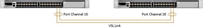
- VSL (Virtual Switch Link, Link de Comutador Virtual)
Componentes Utilizados
As informações neste documento são baseadas no WS-C4500X-32 com o Cisco IOS® Versão 03.05.01. No entanto, o mesmo processo pode ser aplicado a um chassi 4500 com um Supervisor 7 Engine (Sup7).
As informações neste documento foram criadas a partir de dispositivos em um ambiente de laboratório específico. Todos os dispositivos utilizados neste documento foram iniciados com uma configuração (padrão) inicial. Se a rede estiver ativa, certifique-se de que você entenda o impacto potencial de qualquer comando.
Configurar
Note: A Cisco recomenda que a conversão para VSS seja feita em uma janela de manutenção, se possível.
Etapa 1 - Identificar as funções do switch
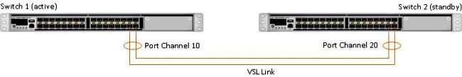
A primeira etapa é identificar o switch que deve ser substituído. Neste exemplo, o switch ativo (Switch 1) deve ser substituído. O comando show switch virtual fornece as informações ativas e em espera.
4500X-VSS#show switch virtual

Executing the command on VSS member switch role = VSS Active, id = 1

Switch mode                  : Virtual Switch
Virtual switch domain number : 100
Local switch number          : 1
Local switch operational role: Virtual Switch Active
Peer switch number           : 2
Peer switch operational role : Virtual Switch Standby

Executing the command on VSS member switch role = VSS Standby, id = 2

Switch mode                  : Virtual Switch
Virtual switch domain number : 100
Local switch number          : 2
Local switch operational role: Virtual Switch Standby
Peer switch number           : 1
Peer switch operational role : Virtual Switch Active
Etapa 2 - Failover
Agora, você entende qual switch está ativo (Switch 1) e qual switch está no estado de standby (Switch 2). A próxima etapa é fazer failover das responsabilidades do plano de controle para o Switch 2, de modo que você possa se preparar para a substituição do Switch 1. O comando redundancy force-switchover executa a operação necessária.
Note: O failover de redundância pode causar inatividade dependendo do estado de redundância operacional. Perceba que essa etapa recarrega totalmente o switch ativo atual (Switch 1) para passar responsabilidades de controle para o peer (Switch 2).
4500X-VSS#redundancy force-switchover
This will reload the active unit and force switchover to standby[confirm]
Preparing for switchover..

*Mar  2 13:38:06.553: %SYS-5-SWITCHOVER: Switchover requested by Exec. Reason:
  Stateful Switchover.
<Sun Mar  2 13:38:09 2014> Message from sysmgr: Reason Code:[3] Reset Reason:
  Reset/Reload requested by [console]. [Reload command]
Etapa 3 - Verificar o failover
Antes de remover o switch defeituoso, você deve verificar se o failover do sistema foi concluído. Para verificar o estado de redundância, insira o comando show redundancy.
4500X-VSS#show redundancy
Redundant System Information :

------------------------------
       Available system uptime = 1 week, 3 days, 22 hours, 37 minutes
Switchovers system experienced = 8
              Standby failures = 0
        Last switchover reason = user_forced

                 Hardware Mode = Duplex
    Configured Redundancy Mode = Stateful Switchover
     Operating Redundancy Mode = Stateful Switchover
              Maintenance Mode = Disabled
                Communications = Up

Current Processor Information :
------------------------------
               Active Location = slot 2/1
        Current Software state = ACTIVE
       Uptime in current state = 55 minutes
                 Image Version = Cisco IOS Software, Cisco IOS-XE Software, Catalyst
                                 4500 L3 Switch Software (cat4500e-UNIVERSAL-M),
                                 Version 03.05.01.E RELEASE SOFTWARE (fc2)
Technical Support: http://www.cisco.com/techsupport
Copyright (c) 1986-2013 by Cisco Systems, Inc.
Compiled Sat 23-Nov-13 00:46 by prod_re
               BOOT = bootflash:cat4500e-universal.SPA.03.05.01.E.152-1.E1.bin,1;
        Configuration register = 0x2102

Peer Processor Information :
------------------------------
              Standby Location = slot 1/1
        Current Software state = STANDBY HOT
       Uptime in current state = 0 minute
                 Image Version = Cisco IOS Software, Cisco IOS-XE Software,
                                 Catalyst 4500 L3 Switch Software (cat4500e-UNIVERSAL-M),
                                 Version 03.05.01.E RELEASE SOFTWARE (fc2)
Technical Support: http://www.cisco.com/techsupport
Copyright (c) 1986-2013 by Cisco Systems, Inc.
Compiled Sat 23-Nov-13 00:46 by prod_
               BOOT = bootflash:cat4500e-universal.SPA.03.05.01.E.152-1.E1.bin,1;
        Configuration register = 0x2102
Na saída, o estado do software atual = STANDBY HOT mostra que o sistema está estabilizado e totalmente sincronizado neste momento. Agora você pode prosseguir com a remoção física do switch.
Etapa 4 - Remoção do switch
Neste momento, o switch com falha está pronto para remoção física. É muito importante perceber que, se sua topologia não for totalmente redundante na remoção, você poderá manter um impacto no serviço. A Cisco recomenda que você implemente o Multichassis EtherChannel (MEC) para ajudar a garantir que os links permaneçam ativos.
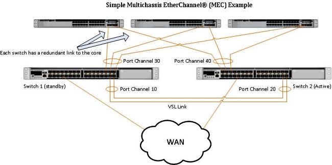
Note: O MEC é um EtherChannel com portas que terminam em ambos os switches do VSS. Um MEC VSS pode se conectar a qualquer elemento de rede que suporte o EtherChannel (como um host, servidor, roteador ou switch).
Etapa 5 - Preparar e instalar o switch de substituição
Você deve usar a mesma imagem do Cisco IOS e o mesmo conjunto de recursos de licença no chassi em standby para esse chassi para ingressar corretamente no domínio VSS atual. Este exemplo envolve o download e a instalação da versão 03.05.01 para corresponder ao par atual. Uma vez instalados, os links físicos devem ser conectados no local exato do switch que foi substituído e, em seguida, o switch deve ser inicializado. Agora, o switch deve ficar on-line com uma configuração em branco e em um estado autônomo, já que ainda não foi configurado como um membro VSS.
Etapa 6 - Configurar e participar do VSS
Você deve definir o domínio VSS e o número do switch.
Note: Essas são as mesmas informações que o switch anterior teria usado. Neste exemplo, o domínio é 100 e o número do switch é 1.
4500X-VSS(config)#switch virtual domain 100
4500X-VSS(config-vs-domain)#switch 1
Em seguida, você deve configurar as interfaces físicas e os canais de porta que são usados para o link VSL.
4500X-VSS(config)# interface Port-channel 10
4500X-VSS(config-if)#switchport
4500X-VSS(config-if)#switch virtual link 1
4500X-VSS(config)# int range tenGigabitEthernet 1/1/15-16
4500X-VSS(config-if-range) channel-group 10 mode on
Por fim, você deve converter o modo do switch de autônomo para virtual. Uma vez feita essa configuração, o switch é recarregado.
4500X-VSS# switch convert mode virtual
Quando o Switch 1 conclui seu recarregamento, ele detecta o switch VSS ativo atual do link VSL e sincroniza automaticamente a configuração.
Verificar
Seus switches agora devem estar de volta em um VSS totalmente redundante. O comando show switch virtual garante que cada switch esteja no estado correto. Para verificar se você está de volta no stateful switchover (SSO) ou no estado de hot standby, insira outro comando show redundancy.
4500X-VSS#show switch virtual

Executing the command on VSS member switch role = VSS Active, id = 2

Switch mode                  : Virtual Switch
Virtual switch domain number : 100
Local switch number          : 2
Local switch operational role: Virtual Switch Active
Peer switch number           : 1
Peer switch operational role : Virtual Switch Standby

Executing the command on VSS member switch role = VSS Standby, id = 1

Switch mode                  : Virtual Switch
Virtual switch domain number : 100
Local switch number          : 1
Local switch operational role: Virtual Switch Standby
Peer switch number           : 2
Peer switch operational role : Virtual Switch Active


4500X-VSS#show redundancy
Redundant System Information :

------------------------------
       Available system uptime = 1 week, 4 days, 9 hours, 27 minutes
Switchovers system experienced = 8
              Standby failures = 0
        Last switchover reason = user_forced

                 Hardware Mode = Duplex
    Configured Redundancy Mode = Stateful Switchover
     Operating Redundancy Mode = Stateful Switchover
              Maintenance Mode = Disabled
                Communications = Up

Current Processor Information :
------------------------------
               Active Location = slot 2/1
        Current Software state = ACTIVE
       Uptime in current state = 1 hours, 3 minutes
                 Image Version = Cisco IOS Software, Cisco IOS-XE Software, Catalyst 4500
                                 L3 Switch Software (cat4500e-UNIVERSAL-M), Version
                                 03.05.01.E RELEASE SOFTWARE (fc2)
Technical Support: http://www.cisco.com/techsupport
Copyright (c) 1986-2013 by Cisco Systems, Inc.
Compiled Sat 23-Nov-13 00:46 by prod_re
               BOOT = bootflash:cat4500e-universal.SPA.03.05.01.E.152-1.E1.bin,1;
        Configuration register = 0x2102

Peer Processor Information :
------------------------------
              Standby Location = slot 1/1
        Current Software state = STANDBY HOT
       Uptime in current state = 1 hours, 3 minutes
                 Image Version = Cisco IOS Software, Cisco IOS-XE Software, Catalyst 4500
                                 L3 Switch Software (cat4500e-UNIVERSAL-M), Version
                                 03.05.01.E RELEASE SOFTWARE (fc2)
Technical Support: http://www.cisco.com/techsupport
Copyright (c) 1986-2013 by Cisco Systems, Inc.
Compiled Sat 23-Nov-13 00:46 by prod_
               BOOT = bootflash:cat4500e-universal.SPA.03.05.01.E.152-1.E1.bin,1;
        Configuration register = 0x2102
Problemas comuns
VSL permanece inoperante
Se o VSL permanecer inativo enquanto um ou ambos os switches terminarem a inicialização, você poderá inserir uma situação ativa dupla se não houver um mecanismo de detecção ativo duplo em vigor. O sistema permanece ativo duas vezes até que um supervisor de mesmo nível seja detectado (geralmente ativando o link VSL após a inicialização do switch). Quando a condição ativa dupla é detectada, um dos supervisores é colocado no modo de recuperação e desliga todas as interfaces locais para o chassi em que está. Quando o link VSL estiver totalmente restaurado, o switch/supervisor no modo de recuperação deverá ser recarregado para que possa renegociar adequadamente como um standby no VSS.
Troubleshooting
Para verificar o link VSL, insira:
4500X-VSS#show switch virtual link

Executing the command on VSS member switch role = VSS Active, id = 2

VSL Status : UP
VSL Uptime : 11 hours, 53 minutes
VSL Control Link : Te2/1/1
VSL Encryption : Configured Mode - Off, Operational Mode - Off

Executing the command on VSS member switch role = VSS Standby, id = 1

VSL Status : UP
VSL Uptime : 11 hours, 53 minutes
VSL Control Link : Te1/1/1
VSL Encryption : Configured Mode - Off, Operational Mode - Off
Para que o VSS opere com redundância de SSO, ele deve atender às seguintes condições:
- Versões de software idênticas em ambos os switches
- Consistência de configuração de VSL
Na sequência de inicialização, o switch VSS em standby envia informações do switch virtual do arquivo de configuração de inicialização para o switch VSS ativo.
O switch VSS ativo garante que essas informações correspondam corretamente em ambos os switches:
- Domínio virtual do switch
- Nó virtual do switch
- Prioridade do switch (opcional)
- Canal de porta VSL: switch virtual link identifier
- Portas VSL: número de channel-group, desligamento, número total de portas VSL
Informações Relacionadas:
 Feedback